Design and build side-shaft hit and miss engine from bar stock

Home Model Engine Machinist Forum

Help Support Home Model Engine Machinist Forum:

This site may earn a commission from merchant affiliate links, including eBay, Amazon, and others.
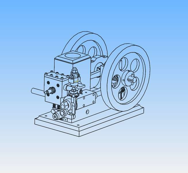
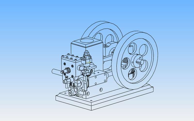
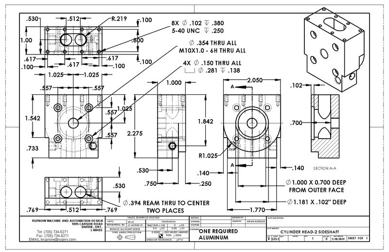
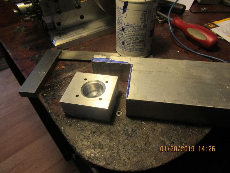
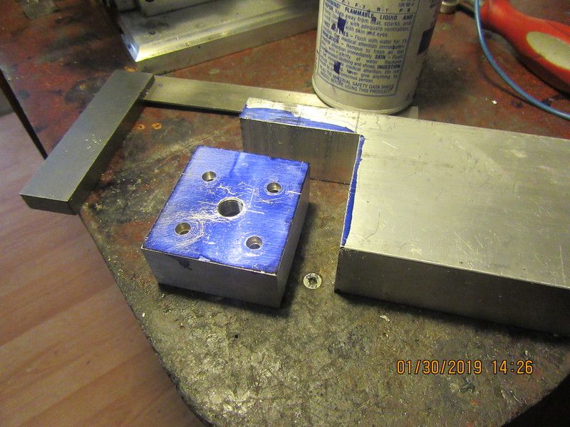
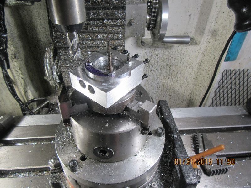
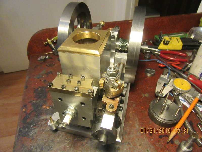
So---Here we are, hitting and missing with both flywheels on. I set the flywheels up in my lathe and turned 1/8" material from both sides to lighten them. Building the engine and getting it to run consistently was the easy part. Getting the hit and miss to work consistently has driven me to -----poetry??
What is better than Spring, and a maidens kisses
---When your hit and miss engine hitses and misses!!!
 
Thanks Ghosty. I've had quite a struggle with the hit and miss mechanism to get it to this stage. The governor itself works amazingly well. The problems I have had were more to do with how the governor "shakes hands" with the engine. The engine itself was relatively straightforward, for a "first of". I have a bit of tidy up work to do on the engineering drawings and then I will be selling drawing packages of the entire engine. The next person to build this engine won't have to do a lot of the "trial and error" stuff that I have sorted out---Brian.
 
There has to be something wrong with the forum software. My still pictures are showing up in all the other forums I post on. I will try to reach Angie and see what is going on.
 
Brian, I can see both videos but like many others no still pics.
Your hit and miss now sounds much more "gooder" ;). Just like I reckon it should.
A bit of tidying up or refinement as you say but either way it's a good'un.
Congrats,
John B
 
If anyone would like a complete set of engineering drawings to build this engine with it's governor, I charge $25 Canadian funds for the total package. You can send it to my Paypal account where I am registered under [email protected] and please specify which engine you want plans for. This is not an engine for first time builders. I would say that to build this engine you should have at least two or three other successful builds of i.c. engines completed. It is not a particularly cheap engine to build either, because of the two sets of gears involved. The drawings are in inch measurements and will not be offered in metric. You will need both a lathe and a mill to build this engine. There are approximately 50 drawings. At present, I do not know of anyone else in the world offering drawing packages for a side shaft hit and miss engine made totally from bar stock, no castings.--Brian Rupnow
 
All of the drawings have been updated and saved as pdf files. I have never seen a governor like this before, but it works and that's what matters. It is mind bending to get your head around it. There is a total of 60 drawing sheets.
Fso8p6.jpg
 
I have thought long and hard about how happy I am with this engine, and I'm not terribly impressed---yet. I am going to make a few changes. The engine and the governor remain essentially unchanged, however the face cam and the cylinder head are going to change radically. Craig Deshong would quickly recognize what's going on here.---
gg8q16.jpg
 
Chalk up another runner. Great work Brian.
 
I am going to change directions now. Although the engine ran, and ran very well after I muddled through the carburetor and anti backflow valve issues, I'm simply not satisfied with the hit and miss action from the engine in its current state. I am going back to a much more conventional cam shape which will act on the exhaust valve thru the rocker arm. The basic engine remains unchanged, and 95% of the governor remains the same. The changes will mainly be in the cylinder head, and the fact that the valve stems now set vertically and extend thru the underside of the cylinder head. I have seen this set-up on another hit and miss engine where it worked very well.
3bIGDV.jpg
 
I've even been able to find a spot for the carburetor. The carburetor sets much lower than it did on the first go-round, but it is still above the top of the gas tank. I might have to put an extension on the carburetor needle valve to keep my fingers away from the revolving cam. Tomorrow I will make the new cylinder head. I can re-use the valves, valve cages, valve springs, spring retainers, and exhaust pipe and carburetor.
sMdQw5.jpg
 
People always like to see "in process" shots. I checked my stock this morning and all of my 1" aluminum was about 0.015" undersize, but I did find a bar of 3 x 1 1/4" stock. I cut out a piece on my bandsaw, then squared it up and milled it to 1" thick. The bolt pattern was laid out, drilled, and counterbored for #6 SHCS. Since I had set the part up in my mill vice and zeroed on the sparkplug (which is also the center of the cylinder)I drilled the hole for an M10 sparkplug. I then flipped the part over and plunged 0.7" with a 1" diameter endmill, then set up my boring head to put in the 1.181" diameter counterbore.
lbs3PA.jpg

lEscBT.jpg
 
Progress today on the new cylinder head design. It bolts on where it is supposed to. After mounting it I seen that there was potential for interference between the governor weights and the corner. Fortunately there is a lot of material in the corners, so I was able to remove some material. I may have to take a bit out of the water reservoir for clearance as well, but I will take a "wait and see" attitude with that.
b9vv68.jpg
 

Latest posts

Back
Top