Design and build side-shaft hit and miss engine from bar stock

Home Model Engine Machinist Forum

Help Support Home Model Engine Machinist Forum:

This site may earn a commission from merchant affiliate links, including eBay, Amazon, and others.
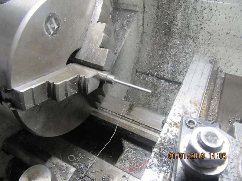
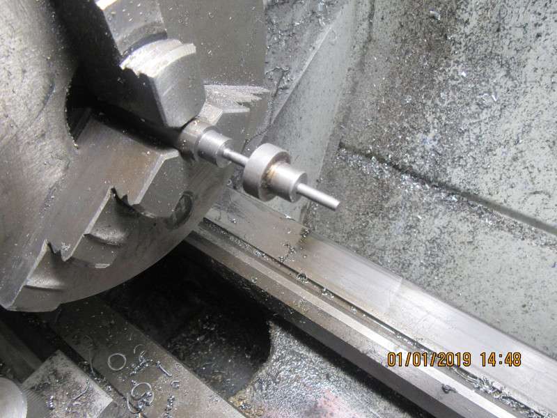
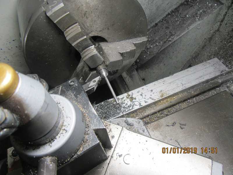
Now we get to the last third of the valve stem. Very much the same as the previous two steps, but when you get down to 0.135" diameter over the full length there is one more thing to do. we have left 0.010" oversize on the full length of the stem. Now you could work it down the rest of the way with 200 grit carborundum cloth, but it would take an awful lot of polishing. I prefer to back the cutting tool all the way out past the end of the valve stem and advance it .002", then take two or three cuts full length at that setting. Then advance it another .002" and take two or three full length cuts at that setting. Measure the portion of stem closest to the chuck, and you should be down to about 0.127". Don't measure out at the unsupported end, because it will have deflected away from the cutter and will give a false reading. And remember--measure very carefully. If we go below 0.125", we have ruined the part. Now is the time to very carefully start polishing with your carborundum paper--and remember--the part will be larger at the unsupported end than the other end. Work the part down and keep trying to slip your test piece with the reamed hole in it over the valve stem. This is a rather ticklish business, and best learned by experience. Just be sure to shut the lathe off and check frequently with your test piece. You don't want to end up with the stem undersize. once you have reached a point where your test piece will slide all the way, you are ready for the next step.
wZdOZD.jpg
 
Once you have worked the stem down with carborundum paper or emery cloth (This always takes far longer than I thought it would) to a point where your test piece slides all the way up to the end of the stem, you are ready for the next step. (Note that I didn't say the LAST step). Since we already have the topslide set over at the angle we want to cut, we take light machining cuts until we have formed the angled face of the valve. Be careful not to undercut the stem while you are doing this. I would love to say that my valve faces always come out perfectly smooth with a mirror finish,but they don't. That will be taken care of when we are ready to lap the valve into the seat. Do NOT part the valve off from the parent stock at this time. Take it out of the lathe and leave two or three inches of unturned stock to act as a handle while lapping the valve into the valve guide.
91j7aw.jpg

u3KknK.jpg
 
We're closing in on the last steps now. The valves have to have a cross hole drilled thru the ends for a valve collar retention pin. I drill a 1 mm (.039") dia. hole and use a 1mm piece of music wire thru it to keep things together.
lIlCET.jpg
 
Okay, we're going to wind this up for today. Setting on top of the pill bottle is the absolutely wonderful, magical valve seating tool, designed by and copied from George Britnell. This is the tool that takes all of the heartache out of leaking valves. Just push it into the valve cage from the bottom as shown, push medium hard, and rotate it about three times. That will put in a perfect valve seat every time, concentric to the guide portion of the valve cage. This has to be the best tool I have in my entire engine building arsenal.---Thank you George!!! And the last shot shows the newly made valve setting in what will be it's final home, after lapping the valve into the seat and cutting off the extended handle.
CyEY91.jpg

yIKZ0Q.jpg

O6vn5E.jpg
 
Today I caught a two hour break in the middle of a design job, waiting for information---So, I hustled my butt into the machine shop and made a second valve. The only time I ever wish I had a toolpost grinder is when I make valves. It would be SO nice to grind the face of the valve when I have the valve set up in the lathe. The valves will work just fine once they are lapped into their respective seats, but gee, it would be nice to put a ground finish on them.
gKiq9o.jpg
 
This morning I lapped the valves into their seats and trimmed the handles off the end of the valves. Spring retainers were made from brass and the springs were installed. The spring on the exhaust valve seems about right. The spring on the intake valve may be a little bit too strong for an atmospheric valve, but I will find that out as work progresses. I have an assortment of different springs that I bought for a project, and if I can find a spring in the box that will work, it saves me from having to buy one.A head gasket was made from 0.030" general purpose gasket paper from the automotive store, and the cylinder head mounted in place. These engines run cool enough that I don't bother to use some high tech heat resistant material for a head gasket.
OnfgNn.jpg

HK65f7.jpg
 
And for all of you who have been ragging on me for years to not hold a milling cutter in a chuck---Today you get to have the last laugh. I have been saving a beautiful piece of brass to make a polished top for the water reservoir. I went to relieve it all around the edges this morning, and decided to use my newest milling cutter, which happens to be 7/16" diameter. I actually was going to use a proper collet to hold the cutter, but the shank on the damned thing is 7/16" also. I only have two sizes of collets, 3/8" and 1/2"----so---I held it in the chuck. A picture is better than a thousand words. That cut in the brass was supposed to be parallel to the top and bottom. Ah POOP!!! And that was the only brass I had. The cutter pulled out of the chuck and was heading for China and I didn't notice till it was too late.
CF5vdR.jpg
 
Now that I am totally disgusted with myself for ruining a perfectly good piece of brass, I think I'll do something else. I'm running out of things to build, but I want to see how things look up around the face cam and rocker arm. I think I will make the rocker arm support. Remember---"If at first you don't succeed--Screw it!! Do something else instead!!!"
LbmAQU.jpg
 
I woke up far too early this morning and decided I should do something before I have to disappear for a 10:00 meeting. I managed to get the rocker arm support finished and silver soldered together, and made up a cam follower wheel from 01 steel, with an oilite bushing. Depending on what happens at the meeting, I may try and finish the rocker arm today.
AphnzH.jpg
 
How do you edit a post now? I've been reading thru this whole article tonight, and I see I have a mistake in post #137. I don't know what I have to do to edit the post and correct it.
 
Brian
It is so wonderful to hear the astatic feelings in your voice. I think you have always done very nice design work and to hear you say you are happy is like the icecream on the cake. I have enjoyed all you do.
Nelson
 
Thanks ghosty--I found it and fixed it. I had originally written 'An included angle of 45 degrees'--It should have said "An included angle of 90 degrees."---Brian
 
Back in 2016 I had the notion that my Kerzel hit and miss engine would run better with heavier flywheels and a larger carburetor.--It didn't, but I have saved that carburetor and a one way valve for the future. The future has arrived. That engine and the one way gasoline valve will be mounted on my sideshaft engine.
fwbLX6.jpg

WODrQN.jpg
 
Last edited:
The carb is mounted on the engine. It didn't go without some drama. I had finished and assembled things--it looked a bit crooked so I tweaked it just a teeny bit with my wrench to correct it---And it broke the fitting off right flush with the cylinder head. I was able to carry the whole engine in and mount it on my milling table, drill out the broken stub of brass fitting from the cylinder head, make up a new fitting and reassemble everything.
TTQuW0.jpg
 

Latest posts

Back
Top