Design and build side-shaft hit and miss engine from bar stock

Home Model Engine Machinist Forum

Help Support Home Model Engine Machinist Forum:

This site may earn a commission from merchant affiliate links, including eBay, Amazon, and others.
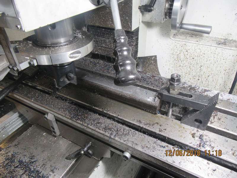
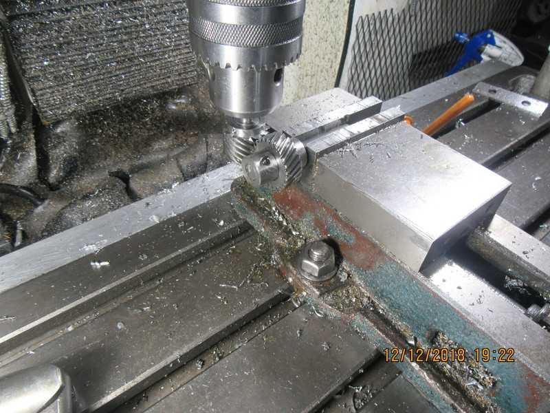
I'm having a very "cranky" morning. You can only buy 1144 stress-proof steel in rounds. It doesn't come in flatbar.-So--I have the length of round stock clamped down and am flattening one side of it. I didn't want to cut the side off in the bandsaw, because my bandsaw has no fence. I have to take off 0.5" of material, and am taking 0.015" depth of cut at 500 rpm. I have taken 0.300" off in theis picture, and have 0.200 left to go. This is one of the few times I think about having a powered axis in the X plane. Once I get this side finished, I was going to flip the part over and do the other side in the mill, but after all the cranking I've been doing, I think I will make up a fixture and bandsaw most of the other side away.
O0Bi23.jpg
 
HAH!!! Old age and treachery and a bandsaw wins again. My bandsaw is slower than the second coming, but is still faster than milling all that material away. Now back to the milling machine for the final dressing.
7c6DsO.jpg
 
So here we are, with the 1 5/8" round of 1144 stress proof flattened on both sides and countersink holes drilled in each end for lathe centers. I have a rather sketchy machinists clamp with a bolt tapped into it for a drive dog, and the con rod journal turned to 0.502" diameter. Next step will be to glue a spacer into the gap, saw away as much waste material as I can, then turn the other diameters.
MrSAtK.jpg
 
This is the point at which you really, really want to be sure what part stays and what part gets sawn off and discarded. You will also see the spacer glued into the gap that was opened in the previous step.
zn2fxm.jpg
 
This morning I trimmed the crankshaft to length, and cut the keyways in both ends of it. I'm just playing a bit now on the CAD. This thing is going to need a gas tank, and although I have always mounted my tanks on the outside of my engines, I have a lot of room available between the engine sideplates. I'm thinking of making up a tank that fits between the sideplates, with one end butting up against the "tower" that holds the cylinder and the cooling water and the other end hanging out the open end with a filler cap on it. The tank outlet would run right thru the bottom of the "tower" and come out the opposite end where it would hook to a line running up to the carburetor. I think it gives the engine a much cleaner look with the gas tank there instead of mounted on the side.
WJdM4q.jpg
 
Brian,

That's a massive pair of flywheels for such a tiny crankshaft! You are going to make sure this one has enough inertia to get the hit-miss to function properly and with the ball bearings it should coast on for ever before needing a fire stroke again. Nice work. I just built 2 cranks using the same method you used. One is a 1" for a larger engine I'm building and the other is 1/2". They are nerve wracking for sure and the smaller ones even more. I'm following along and still searching for the proper bevel gears at a reasonable price for the larger J&E Junior engine I want to convert to a side shaft. Thanks for what you do to keep this hobby interesting. I have a friend in neighboring New York state that is building a Nanzy along with the one I'm building. We are only 25 miles from each other so it's easy to visit.

Jim in Pa
 
Jim--It is really nice to have someone in the same hobby close enough to drive to in half an hour. I have a fellow here in Barrie, who is interested in the hobby, but he has a thousand other things going on in his life at the same time, so I don't see him very often.---Brian
 
Dan is a dairy farmer by trade and has no spare time from spring planting to fall harvest but in the winter all he has to do is milk the cows twice a day so he gets some modeling done in between. He has an Amish lad do the messy chores. Dan had built a nice Farm Boy hit miss and then lost interest because he didn't know anyone else in the hobby until he met me at Cool Springs a couple years ago. Now we are {building friends} so to speak. He is not much of a internet person so I doubt he knows about this forum yet, but he soon will! Have a nice day Brian.
 
Jim--It is really nice to have someone in the same hobby close enough to drive to in half an hour. I have a fellow here in Barrie, who is interested in the hobby, but he has a thousand other things going on in his life at the same time, so I don't see him very often.---Brian

Brian,

You could always bop on over to Busy Bee tools and ask around about hobbyists with similar interests. When I lived in Barrie (until about 10 years ago) there was a transplanted Englishman (name escapes me entirely now) who used to go into Busy Bee regularly to buy tools and sundries; maybe he's there still. There were at least two other fellows around, too (Fred Something and another forgotten man! I know, this doesn't help.).

Of course, if I and my old Logan lathe were still on Sunnidale Rd. I'm sure I could find you...
 
The old English guy is dead. My friend in Barrie bought all his machine shop equipment from his widow. I don't know a Fred.
 
I had "real work" today, so nothing done on the engine. I did however order enough aluminum to make the base, both side plates, and the "tower" which holds the cylinder and is the water reservoir. This cost about $75 Canadian. I will pick it up tomorrow. All that leaves outstanding is material for the cast iron cylinder and piston, and I may go to a bronze rod--not sure about that yet. I'm having ongoing issues with my back from standing at the machines all day, so a day of "real work" not only makes me a bit of money, but means I get to set in my computer chair all day and not have an aching back at the end of the day.
 
I've been way to busy with real work (everybody is spending their budget money before the year turns over) to do much hobby machining. I did however, squeeze an hour out tonight to modify the helical gear set. The camshaft gear comes in at 0.370" diameter bore, so needed to be reamed to .375. The crankshaft gear comes in way oversize in the bore, so it had to have a steel bushing made and loctited in place to fit my 1/2" crankshaft. There was nowhere to put set screws in it, so I turned 3/16" of tooth off one side and put in two #6 set screws and a keyway. In this picture I had them both up and running in my milling machine, and they mesh just fine. I probably won't get much free time between now and Christmas, but I will post any further work that gets done on the engine.---Brian
ZTDP3D.jpg
 
I've managed to find enough time in the evenings and this morning to whittle out a pair of sideplates and bearing caps. There is some fettling and sanding yet required, but it is progress. That piece they are resting on is destined to become the base.
GaqfUD.jpg
 
I have the baseplate up on the mill now, and before I start putting holes in it, I am running that ornamental fillet around the four sides. That fillet makes a baseplate very pretty, but putting the fillet in is not one of the more fun aspects of machining. I have a 5/8" ball nose endmill, and it clunks and thumps like crazy. It takes numerous passes, and even after your finished machining the part, it still requires a fair bit of sanding with 200 grit paper wrapped around a dowel to get all of the wavy lines out of the fillet. It actually machines a lot better with "climb" milling than it does with conventional milling.
AY0AIO.jpg
 
I have used tungsten wood router bits to make such decorative features in the past and they work incredibly well in aluminium. I was nervous to try at first as the cutter looks nothing like a 'normal' cutter for metal, but had no issues at all. For only a couple of $$ it's worth your while to grab one and have a test on a bit of scrap.
 
OH MY!!!! Everything fits, everything goes round and round and up and down. All the parts I've made are together for the first time, and I'm stoked. The helical gears mesh properly. Next thing on the build list will probably be the tower that holds the cylinder and becomes the water jacket.
7tarDm.jpg

3zXUjM.jpg

HDcQ9V.jpg
 
After an intense afternoon of Christmas shopping with good wife, I escaped to the shop and made the support block (with bronze bushing) for the side-shaft. I have hidden the near side flywheel so you can see the part I'm talking about, colored grey, right next to the pink helical gear.Something was rotten in Denmark, because when I tightened the bolts which held it in place, nothing would turn. Ah Poop!!! Some detective work showed that the backing of the support was about .006" short. I have an old ratty set of feeler gauges, and since I didn't want to remake the part, my .006" feeler gauged sacrificed it's life as a shim under the block. Now everything turns freely. I am absolutely fascinated by this engine. Some engines I build, and they work, and I'm pleased. Other engines like this one grab my heart and give it a squeeze. Probably it's silly to be so taken with a collection of steel, aluminum and brass parts, but it always surprises me and makes me feel great when it happens.
GbbSNw.jpg
 
And if you wondered what was lurking under the far side flywheel, well here it is. My "standard" set of Chrysler ignition points, setting on a mounting plate with a handle that lets me advance or retard the timing while I'm setting up the engine to run. It's a little more work to do it this way, and once the timing is set, it never gets adjusted again. I have found that it is a great help when first setting up an engine to run at the best idle, to be able to adjust the timing while the engine is actually running.
pYxmlo.jpg
 
Back
Top