Over center manual cone clutch

Home Model Engine Machinist Forum

Help Support Home Model Engine Machinist Forum:

This site may earn a commission from merchant affiliate links, including eBay, Amazon, and others.
Hi Brian. Very interesting project. I´m trying to get a grasp on how it works.. Am I right if the spring will always keep an axial pressure on the bearings? That the bearings actually have to hold against the spring force in engaged position? If so I would expect some drag and short lived bearings. Maybe I misread the drawings.
I´m thinking like a car clutch. The spring tension is not pushing anything else than the clutch plate, until you press the pedal (then the crank shaft axial bearing has to take the spring tension).

Rudy
 
The small bearings don't touch anything when the clutch is engaged. The spring holds the cone into the cup. The small bearings do see pressure for an instant as the clutch is being disengaged, but as soon as the "driven" side is disconnected from the "drive side" it stops turning.
 
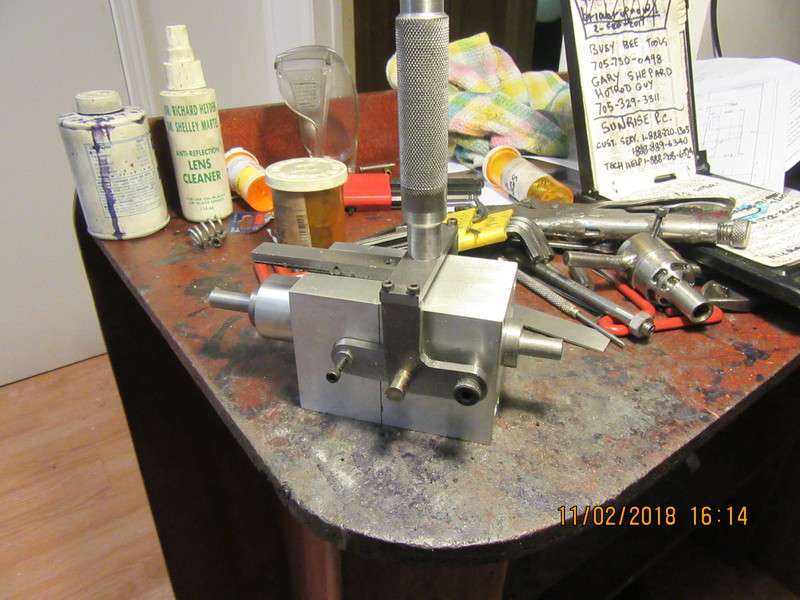
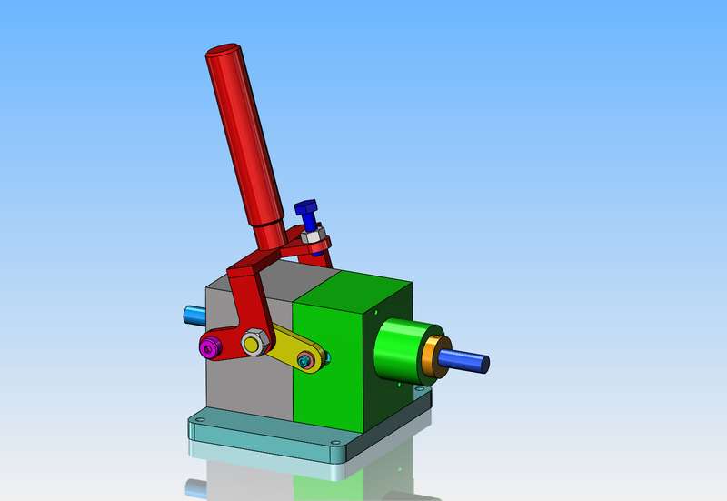
First results are in, and they are very positive. When the clutch is disengaged, there is absolutely no connection between the cone and the cup, and no drag at all. When the clutch is engaged, it locks up the cup and cone shafts. The pressure required to get the handle to "cam over" is quite small. I may rethink the adjustment I had modelled, because it looks like I can add one adjusting screw to the bar under the handle to limit how far it goes before it locks.
AZl8b7.jpg
 
I have changed the adjusting mechanism for the "over center" condition to something a lot simpler and less work. Sometimes when I am designing and building things, I will reach a point part way thru the assembly where I can see a better solution to a problem than I designed in the first place. This is not unusual, and as everything I design is a "prototype" it doesn't bother me. (as long as I haven't already made the part). The last thing I need to build is a baseplate which will allow me to bolt this clutch down to my worktable.
i0td1w.jpg
 
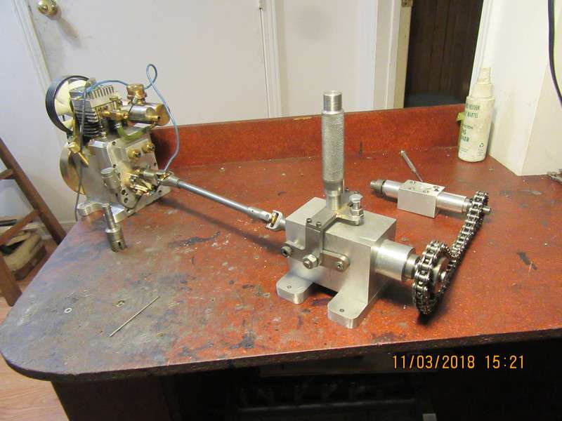
Right on the cusp of an exciting new video---and one of my universal joints flew apart. Video will be delayed until Loctite holding one of the universal joint pins in place sets up. It's colder than a witches tit out in my main garage, and I've been sick for a week. Will put a heat lamp on the offending parts and maybe a video later today--maybe tomorrow. I do know this much---The flathead engine has enough beans to run the clutch mechanism in it's disengaged mode. I was just reaching to engage the clutch when the universal joint flew apart.
 
Brian
Very nice job with the universal joints. That also make it much easier to move to another motor regardless of shaft size. Make the half to the specs and replace with the right size.
Very nice.
Nelson
 
So, today we have the video I intended to make yesterday. The clutch operates just as I had hoped, and the video gives a good overview of the clutch in operation. I have a set of 21 engineering drawings of this clutch, which can be built using a small manual mill and manual lathe. I sell the plans for $25 Canadian funds, contact me at [email protected] The input and output shafts are 3/8" diameter, and both shafts ride on double sealed ball bearings. hope you enjoy the video.---Brian Rupnow
 
I knew the concept of the cone clutch would work, because I built one a few years ago which worked very well, except that it has a "dead" central shaft. I wanted to recreate it, only this time with a "live" central shaft, which offers more versatility. The big issue with any of these smaller "home brewed" clutches is how to keep them engaged or disengaged. If you don't have a lever with a shift gate which the lever snaps into, they have a propensity for jumping into or out of engagement, which can be quite alarming. The "over center" mechanism works very well to solve that problem. It is the same mechanical locking principal as is used on Destaco clamps. This will be my last clutch build for the foreseeable future.---Brian Rupnow
 

Latest posts

Back
Top