"Regal" 0-4-0 Oscillator in Gauge 1, Progress and Updates

Home Model Engine Machinist Forum

Help Support Home Model Engine Machinist Forum:

This site may earn a commission from merchant affiliate links, including eBay, Amazon, and others.

xo18thfa

Well-Known Member
Joined
Feb 27, 2009
Messages
254
Reaction score
46
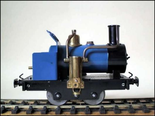
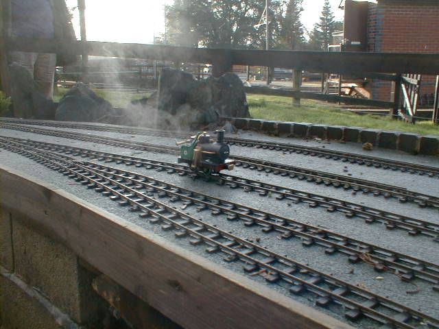
Many years ago I built a Gauge 1 version of Ernest Glaser's "Cracker". Cracker, originally Gauge 0, is a single cylinder, gear driven, single acting oscillating engine with a gas fired boiler. Here are a few examples of Cracker.


The plans for Cracker are available at:

http://home.iae.nl/users/summer/16mmngm/Articles_htms/Cracker.htm

My version of Cracker, named "Chip", is a scale up, convert to inch and round off of Mr. Glaser's plan. The bore is 7/16" with a stroke of 5/8". Gear reduction is 3.25 to 1. Chip has no lubricator, throttle, water gauge or safety valve (the oscillating motor is the safety). The burner is Mr. Glaser's original, converted from metric to inch. A separate car carries the fuel tank. Here is Chip as finished:


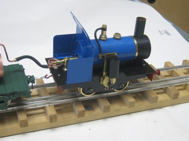
I like the Cracker design a lot and have since built several variants. They are surprisingly powerful and long running little engines. This version, named "Regal", follows the general Glaser plan, but is fired by alcohol with the fuel tank between the frames.

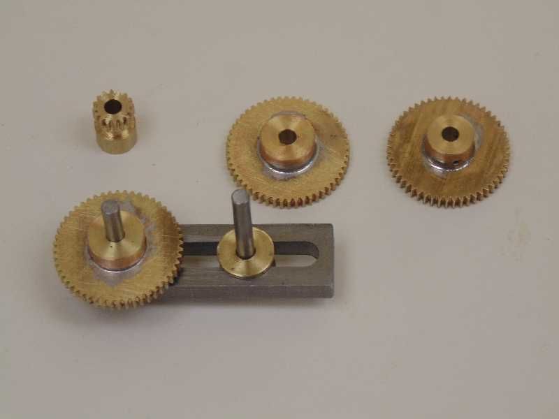
Start the construction with the gear train. The Regal gears are 48 Diametral Pitch. The pinion on the crank shaft is 18 tooth, with gears of 52 teeth. This train provides a gear ratio of 3.25 to 1. I made my own gears for Regal, however, stock gears are available.

http://www.homemodelenginemachinist.com/showthread.php?t=26549


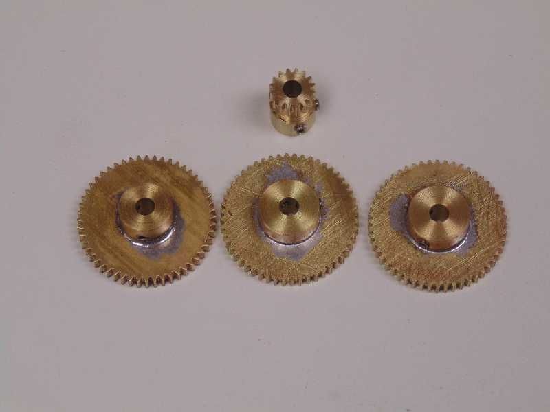
It's best to test the gears for fit prior to making the frames. Ensure the gears turn without any bind, but are not too loose. Carefully measure the distance between pinion and gears and use this dimension for the frames.


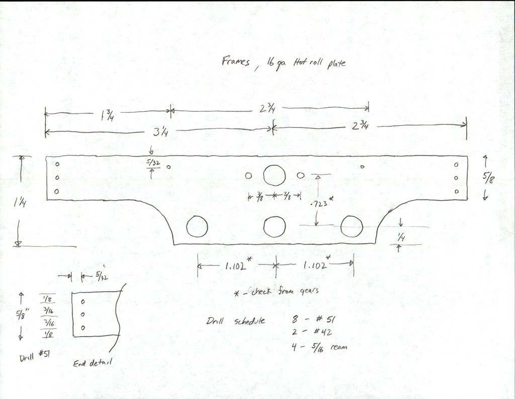
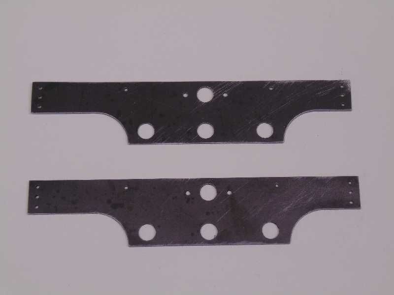
The frames are 16 gauge (approx. 0.059") hot rolled plate. Sheet brass will work as well. Do not use aluminum or stainless steel. Here is the drawing:


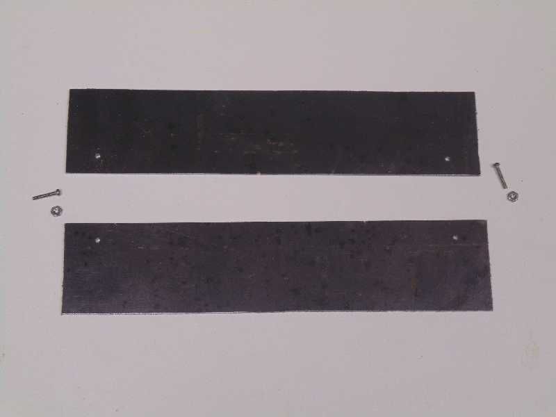
Saw two pieces about 1/8" oversize and clamp together with 0 x 80 machine screws. Place the screws in the lower corners of the frames where they later waste out.


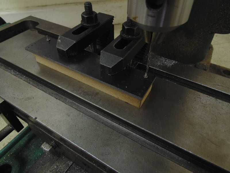
Clamp the frame slabs to the table of the mill. Place a 3/4" thick MDF spacer under the frames to prevent drilling or milling into the table.


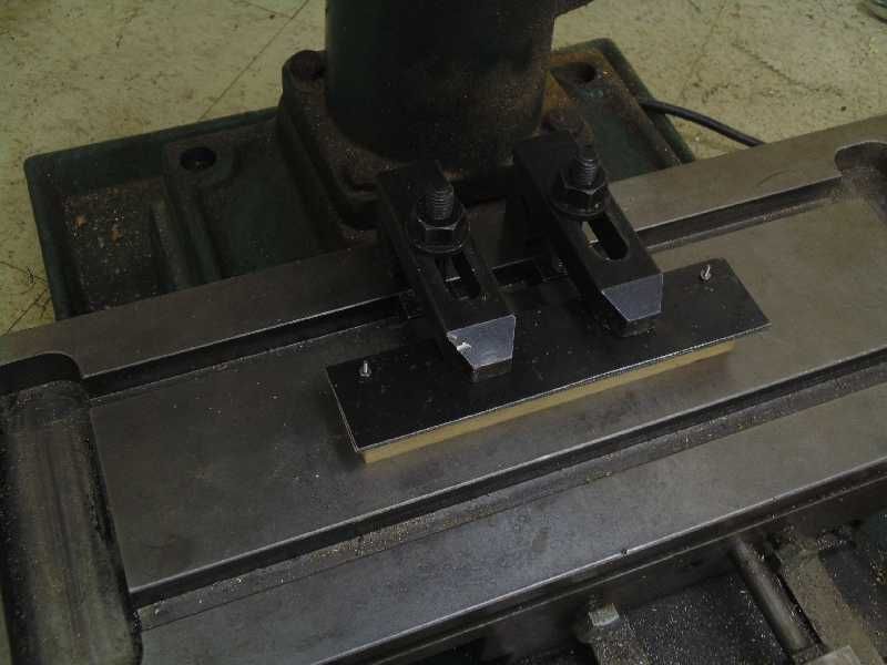
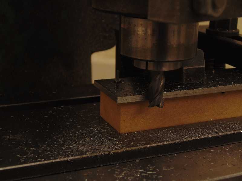
Mill the ends to 6" overall length. Mill one long edge cleanly. This long end is the top of the frame for the next operations.


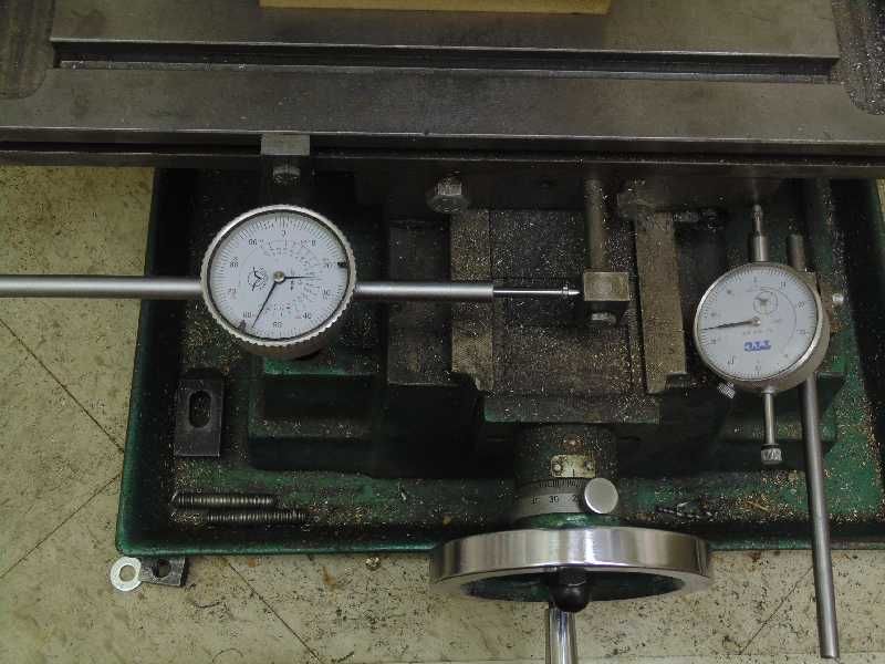
Set up dial indicators on the X and Y axis of the mill table. Or use the DRO if have one.


Locate and drill a total of eight #51 holes for 0 x 80 machine screw clearance.


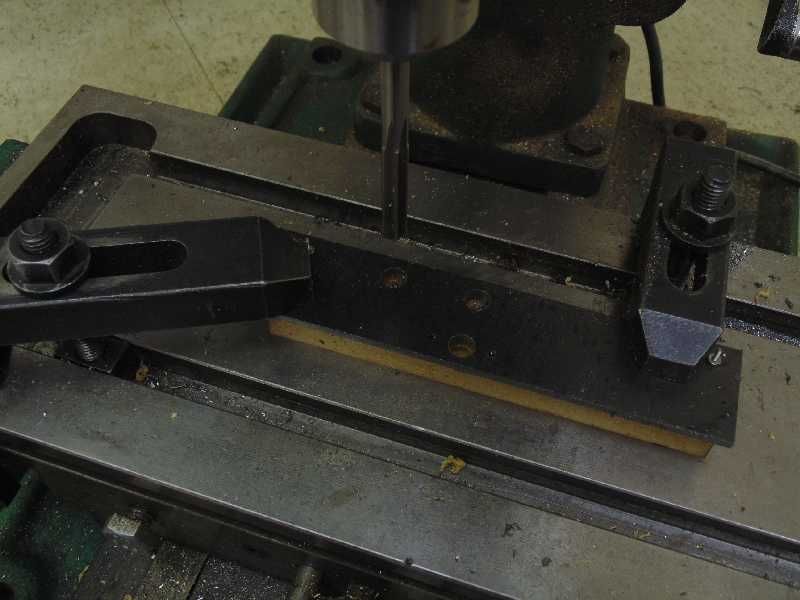
Reposition the milling table clamps, without disturbing the frames to drill and ream holes for axle and crank bearings. These locations are based on the gear train test result. Drill two #42 holes for the engine standard. Holes for the axles and crank bearing must be accurately located. The dial indicators on the mill table makes easy work of the frames.


Remove the frames from the mill and finish the bottom edge. Finish the bottom edge either on the mill or by hand. Even though Regal is a single cylinder engine, both frames are drilled for the engine. This way the engine can be placed on either side.


Next time, we'll work on the end beams, assemble the frame, make and install the bearings.
 
Make the end beams from the same material as the frames. Here is the drawing for the end beam and other parts used in this section.


Use the same general method to make the end beams. Regal uses a brass screw in eye hooks as couplers. Drill the end beam exactly in the center for a tight fit screw hook and soft solder in place. Shape the end beam as desired, but maintain overall dimension and spacing of holes.


Next are the bearings. There are 8 bearings total. Seven are for axles, gear counter shaft and the flywheel end of the crank. One extra length bearing is on the cylinder end of the crank. Make the bearing from 3/8" diameter round brass. Use a squared end parting tool work for all the machining steps.


Use the parting tool to turn the shoulder portion of the bearing. Turn the shoulder slightly under 5/16" so they fit easily in the frames. Center drill and drill with #21.


#21 drill is 0.159" diameter. The axles are from 5/32" ground and polished stock. The fit is very slightly loose, but not sloppy. Next part the bearing off the stock.


The frames and end beam assemble with brass angle gussets in the corners. Make four gussets as shown in the drawing. Brass angle is ideal, however, aluminum angle available from Lowe's or Home Depot works fine. Here are the frame parts ready to assemble.


The hot rolled steel plate used for the frames and end beams has a blackened scale coating from the rolling process. Prior to assembly, remove the scale by soaking the parts in swimming pool acid. Assemble the frame using 0 x 80 machine screws and model hex nuts. Cut some lengths of 5/32" diameter ground and polished steel, either cold rolled or stainless. Slip the bearings into position using the axles for alignment.


The frames are drilled to allow the engine to be on either side. Ensure the longer crank bearing is on the side of choice. Flux and soft solder the bearings in place using the axle stock for alignment.

Clean up the frame assembly and test fit the gears. Everything turns smoothly.


Next time is wheel turning.
 
The wheels on Regal follow the Gauge One Model Railroad Association (G1MRA) recommended practice. G1MRA's practice is available from their website. The G1MRA practice calls for a 3 degree taper on the wheel rim and 20 degree taper on he outer edge of the flange. Wheels can be either steel, brass, stainless, cast iron or aluminum. Aluminum works very well for wheels. It is easy to machine and has a great deal of friction on the rails. Here is the wheel drawing:


Start with a 1/2" long slab of 1-3/8" diameter round stock. Chuck in the three jaw chuck.


Drill and ream to 5/32" diameter for the axles. Face turn the outer hub to 3/8" diameter and 0.069" deep. The .069 hub depth allows for a 0.010" side to side clearance of the wheel sets in the frames.


Next turn a shoulder that serves as the wheel rim. Leave the rim turned straight for now. The 3 degree taper will come later.


Turn a decorative recess about 1/16" deep.


Reverse the wheel blank in the chuck and turn the backside. Turn the flange to a thickness of .060".


Repeat the process 3 more times. Here are the wheel blanks ready for final turning.


Make a turning spud from a length of the axle materiel and scrap 3/4" round stock. "Loctite" the axle material into the spud body. Tap the end for 4 x 40 machine screw.


Mount a wheel blank on the spud. Use a dial indicator to ensure the blank is perfectly centered in the 4 jaw chuck.


Set the compound rest on the lathe to 3 degrees. Take very light cuts until the entire rim is tapered to 3 degrees. Be careful not to reduce the root diameter of the wheel.


Turn all the wheel rims with the 3 degree setting. The set the compound to 20 degrees to taper the flanges.


After tapering the flange, use a hand file to round over the flange and break the sharp corner on the edge of the rim. Finish the remaining 3 wheels in the same manner.

Clamp the wheels in the milling machine vice at about 30 degrees. Sandwich the wheel in wood to protect the flanges. Drill and tap for a 6 x 32 set screw. Drill into the corner between the hub and wheel back.


Wheels all finished.


Next time is the crank shaft, flywheel and finish up the rolling chassis.
 
The flywheel is a two step turning job. Here is the drawing:


Any metal, except aluminum will do for the flywheel. Aluminum is probably too light. The flywheel has to be a bit robust or the engine will run very "jerky" on the track. This flywheel is bronze. Chuck a 9/16" length of 1-3/4" or 2" diameter stock and turn the outside.


Grip the flywheel by the inner recess to face the back and turn the rim. Break the sharp corners on the rim with a hand file. Polish the rim to VERY high luster. Everyone will see it.


Clamp the flywheel in the mill vice and tap for a 6 x 32 set screw. Same operation as on the wheels.


The crankshaft is a 3 piece fabrication. Here is the drawing.


The first piece is the main shaft. Cut a 3-7/32" length of 5/32" diameter ground and polished stock. Drill and tap the end of the shaft with 4 x 40.


Also cut a 5/16" length of 1/8" diameter ground and polished stock and tap with 0 x 80. This is for the wrist pin. "Loctite" machine screws into the ends of the shafts.


Be sure to use high quality "ground and polished" stock for the crankshaft and axles. G&P is exact diameter, perfectly round and exceptionally smooth. Regular rolled stock will work, but G&P is superior. Use either free machining 12L14 steel or 303 stainless.

Next, face off a 3/16" length of 1" diameter stock for the crank web. This web is bronze for a nice contrast. Center drill and tap with 4 x 40. Secure the web blank on a piece of scrap material in the mill vice. Tap with 0 x 80 exactly 5/16" from the center of the main shaft.


Trim the 4 x 40 and 0 x 80 machine screws to a length of 5/32".


"Loctite" the crank web to the main shaft. Chuck the main shaft and crank web in the lathe. Turn to final diameter and width.


"Loctite" the wrist pin into the crank web and the crankshaft is done.


Use Loctite #242 (the red stuff) for these applications. #242 is a high strength threadlocker for close, smooth finish surfaces. Autozone usually carries #242.

Time to assemble the rolling chassis. Trim the length of the axles about 1/32" proud of the bearings on both sides. The back-to-back measurement on the wheels is exactly 1.574". While putting the chassis together, bolt on eight angle brackets for the footplate. The angle brackets are 1/4" x .025" brass hobby angle drilled for 0 x 80 machine screws.


Put a drop of light machine oil on each bearing. It will roll like a champ.

Next time is the start of the motor unit.
 
The motor for Regal is a single cylinder, single acting oscillator. The bore is 7/16" with stroke of 5/8". Oscillators are easy to build and very powerful. "Chip" is the first oscillating locomotive I built, its been running strong for years. Here is Chip at the National Summer Steamup, I think in 2013.

[ame="https://www.youtube.com/watch?v=olNsRBN_M1I"]https://www.youtube.com/watch?v=olNsRBN_M1I[/ame]

The first part is the engine standard. It consists of the portface and manifold. Here is the drawing.


The first step is clamp some 1" x 1/8" brass to the milling table. Profile the sides and cut a shallow recess to receive the manifold. If you don't have a 1/4" ball end mill bit, hand cut the recess with a round file.


The manifold is 1/4" diameter round brass. Drill and tap both ends with 3/16 x 40 as deep as possible, but don't break thru. Soft solder the manifold to the portface.


Flip the standard over and drill all the holes. The two #43 holes at the top of the standard just break into the manifold.


Cut the standard off the stock. The standard is not quite finish yet. The finish up comes after the cylinder build.


The cylinder is a 1-5/16 long piece of 7/8" diameter bronze. It is usual practice to make mating surfaces from dissimilar metals. So the standard is brass with a bronze cylinder. There are several grades of bronze. Alloy #932 is the most common form. It is a general purpose bearing bronze that is vert durable easy to machine. Here is the drawing for the cylinder and top cover.


Chuck round cylinder sideways in the lathe and machine one side flat.


Machine the other side and port face in a similar manner.


Clamp the cylinder in the mill vice to drill the port hole and tap for the pivot pin.


Make a very small center drill on the bottom of the cylinder for the bore center.


Since the cylinder is an odd shape, it will not chuck properly in a 3-jaw universal chuck. Use a "wiggler" center finder to center the cylinder in the 4-jaw independent. This is the wiggler I made many years ago.


Use the wiggler to adjust each chuck jaw to center the cylinder.


This is enough for now, so we will end here and finish the cylinder next time.
 
With the cylinder block centered in the 4 jaw begin drilling out the bore. Step drill with about 3 or 4 drill bits to 3/8". Then switch to a boring bar. Take several light cuts until the bore is about .010" under 7/16".


To size the bore exactly to 7/16" use a reamer in the tailstock chuck. Feed the ream slowly with the lathe set at its lowest speed possible. They say you don't have to, but I heavily oil the reamer.


Turn the bottom end of the cylinder to remove excess metal.


Even though the ream leaves a very good bore surface, it's still not good enough. The bore need "lapping" to remove the microscopic burrs left by the ream. Turn a piece of wood, either maple or oak, to 7/16" diameter. Obtain some fine, #280 grit, grinding paste.


Chuck the wooden lapping rod in the lathe chuck. Apply some grinding compound to the wood lap. Slip the cylinder on and start the lathe. Work the cylinder back and forth on the lap for about 15 to 20 seconds. That's all it needs.


The process requires a lapping rod that is softer then the cylinder, in this case wood. The grinding paste embeds itself in the softer lapping rod in order to hone the cylinder surface. If a harder lap was used, the grinding paste would embed in the cylinder wall and cut the lap. The cylinder bore must be as true as possible before lapping. Lapping will not correct a bad bore. When finished, the bore will have a very smooth frosty surface.

Now lap the portface on the engine standard and cylinder. Do this by taping a quarter sheet of #320 wet/dry sand paper tightly a flat surface. Oil the sand paper and gentle grind the port faces with a circular motion. Repeat the process with #400 grit and again with either #1500 or #2000 grit sandpaper. If you don't have the finer paper, #400 is good enough. It will just take a bit longer for the engine to "run in".


When complete the portfaces are dead flat with a smooth frosty surface.


Finally time for the piston. Here is the drawing:


Fabricate the piston with 3 parts, the big end, piston rod and piston. The big end is the hardest part to make. It is 1/4" square stock. To get the big end stock centered in the 3 jaw chuck, make a split collet that fits over the square stock.


Cross drill the big end with #30 to fit the wrist pin. Chuck the stock with collet in the 3 jaw.


Drill and tap with 2 x 56, turn the end a bit then part the big end off the stock.


The piston itself is alloy #303 ground and polished stainless steel. The G&P stainless fits perfectly in the reamed and lapped cylinder bore. Drill, tap and turn according to the drawing being careful not to mar the surface.


Oil the cylinder and try a test fit of the piston. It should slide close but free. The piston should slide freely when blowing in the portface hole by mouth. If it's too tight, give the cylinder a few more seconds on the lap. When all is ready, soft solder the top cover on the cylinder and make the pivot pin.


Assemble the motor onto the frame. The cylinder spring is 1/4" long, 1/4" diameter, 0.020" music wire. The exact spring is McMaster Carr part number 9657K259. An equivalent works fine. Oil everything in preparation for the air test. Put a drop of light machine oil between the cylinder and engine standard.


Hook up a regulated air source to the manifold and block up the engine. This engine runs fast on 6 or 7 PSI. Run the engine for about 30 minutes on air. Stop every 5 minutes or so to disassemble the motor and clean it. Do a "dyno test" with a finger against a wheel. It will take some effort to bog the engine down.

[ame="https://www.youtube.com/watch?v=2yZPM22uW80"]https://www.youtube.com/watch?v=2yZPM22uW80[/ame]

Next time is the footplate and fuel tank.
 
Last edited:
Bob,
I have been following this thread with great interest. Thanks for sharing. I would like to make an engine of this type. I am very much a learner - how does the wiggler work to align work in the four jaw chuck? Also how is it made?
Thanks for any help - DW
 
Hi DW. The short end of the wiggler goes into a center punch spot on the work piece. On the cylinder, it was a very small drilled hole. As you rotate the chuck by hand, the center error on the work piece is magnified by the wiggler on its long end. So if the short end of the wiggler is 1 inch from the pivot ball and the long end is 12 inches, the error is magnified 12 times. You adjust the 4 jaw chuck, and rotate again. Eventually the work piece is centered and the long end of the wiggler is stationary as you rotate the chuck.

Wigglers like this are very old tech. Brown & Sharpe used to make them, but they are antiques now. Here's a better pic of how they are made.


Check your private messages, I have some more info for you.

vr Bob
 
Last edited:
I have sent email by private letter. Thanks for the explanation and added photo.
David
 
The footplate serves as the basis for mounting the boiler, cab and burner assembly. It also provides additional rigidity to the rolling chassis. By this point a few errors have probably crept into the Regal chassis, making it difficult to fabricate the footplate in one operation. Do the footplate in stages, using "fit one part to the next" method.

The footplate is from 1/32" sheet steel or brass. It is possible to mill the footplate as done with the frames. The thin material is just as easy cut with a fret saw and hand filed out. Break all sharp corners with a small chamfer or round over. Here is the footplate drawing to start:


Remove the wheels, axles, gears and motor parts from the chassis. All that will need paint eventually anyway. Turn the frame upside down on the footplate and directly transfer the mount holes.


Next part is the fuel tank. Regal has a single pot, gravity fed, alcohol burner. The goal is to hide the fuel tank as much as possible under the frame. It would be easier to make an over sized tank and install under the rear end of the footplate, but that's what I am trying to avoid. So the Regal tank is rather flat and as long and wide as possible. The flatter profile should also prevent starvation to the burner pot as the fuel level drops.

Previous tests determined that Regal should burner about 0.8 milliliters of alcohol per minute. For a 5 minute warm up and 20 run, that comes out to a 16 milliliter capacity requirement. Doing the conversion, that is about 1 cubic inch. At first I thought that would be possible with a single tank. But math and theory usually never work out, so I went with 2 tanks. A large tank in back and a small one in front connected with a run-a-round tube.

The tank is silver soldered from 1/32" thick sheet brass. The rear tank has an overall dimension of 2-1/8" wide, 1-1/8" long and 11/16" height. Cut a strip of brass 5/8" wide and bend into the rectangular shape and silver solder. Cut the top and bottom sheets rather oversized.


The burner pot itself is a 1/4" nominal (3/8" OD) copper elbow. Trim the elbow so it is a smidgen above the top of the tank. The center of the burner pot is about 1-3/8" in front of the tank. When installed this will put the burner pot about half way between the rear axle and the center gear axle. Silver solder a length of 1/4" brass tubing for a fill tube. Silver solder two #2 x 56 machine screws for mounting the tank to the footplate.


On the bottom of the tank, silver solder a length of 1/4" tube for an overflow. Cut the top of the tube at about a 30 degree angle and push it in until it hits the top of the tank. This will overflow excess fuel out of the tank at about 1/8" from the top.


At this point I changed my mind and added the additional tank in the front. This tank is from 5/8" thin wall square brass tube with the ends silver soldered on. As an alternative, make the forward tank with the same method as the rear tank.


Connect the front and rear tanks a run-a-round tube from 1/4" or 5/16" brass tube.


The fuel tank is a real "cut to fit" job, so no drawings per se. It is actually easy to silver solder the tank. Once silver solder cools, it re-melts at a higher temperature, so there is no worry about the job falling apart on subsequent solderings.

Finally, stuff the burner pot with wick material. Wicks are kind of an art, not too tight, not too loose. Insert the wick well into the rear fuel tank. Ordinary cotton candle wick is an excellent material. Just don't ever let the tank run dry. An alternative is fiber glass. Shape and trim the wick to get a 1-1/2" to 2" flame.

Test burns show this tank will work. It's good I added the front tank, now it has a good 25 minute burn time. With a flame of 1-1/2 inch height, the fuel consumption is down to about 0.60 milliliters per minute. And it burns hot.

Next time is the boiler.
 
Is this continued in another set of postings, or did it just never come to completion? Was looking for a G1 project and this would have been ideal.
 
I've followed your and quite impressed.
 
Unfortunately the OP hasn't visited the site since April 2017 so we may not get another instalment of this build. Pity, it was an interesting read.
 
Yes its a pity that there is no following episode to this quite interesting thread.
I did too 3 "Cracker" locos, very funny and easy to build, particularly if one follows the above thread !
but personally, I would stay on the original gas burner or a pencil torch burner rather than the alcohol burner version, as the heavy alcohol tank, very close to the wick, would be overheated and could easily catch fire before the end of the run...
 
I was also following this build on another forum with the intention of building it
Although apart from the missing boiler info its nearly all done. Looks like the boiler was going to be a simple pot with maybe water tubes or hedgehog .
Iv seen an engine similar running on a you tube video
Ellie The Steam Tram is a nice build and the book is available from Camden. Iv started on it as fill in build for when the bigger builds go wrong or I just need a change
best wishes
 
Back
Top