Muffler for model i.c. engine

Home Model Engine Machinist Forum

Help Support Home Model Engine Machinist Forum:

This site may earn a commission from merchant affiliate links, including eBay, Amazon, and others.

Brian Rupnow

Design Engineer
Project of the Month Winner
Joined
May 23, 2008
Messages
14,969
Reaction score
8,247
Location
Barrie, Ontario, Canada
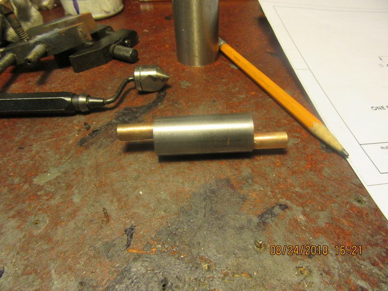
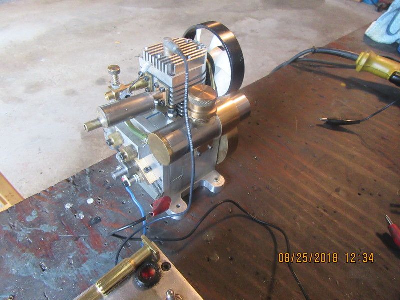
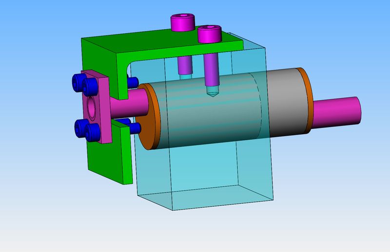
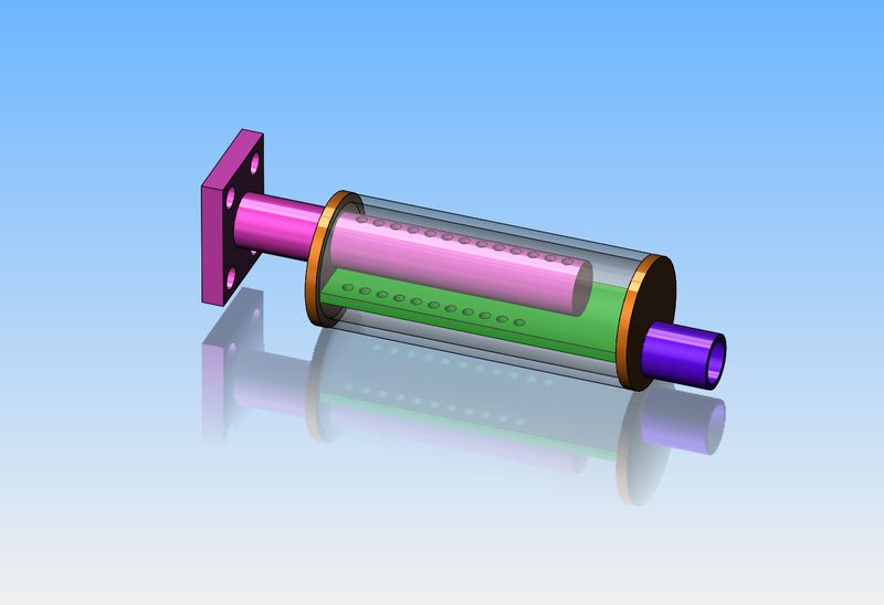
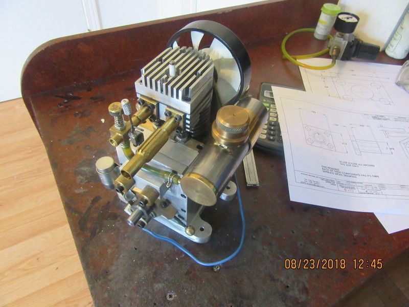
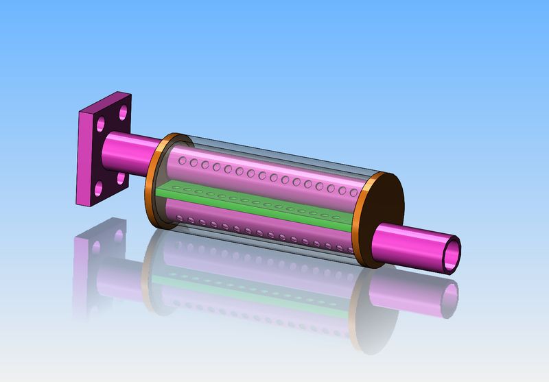
Just for the heck of it---has anyone ever built a muffler for a model i.c. engine? I have designed one this morning, based mainly on guess-work and size constraints. This muffler is designed to fit onto my flathead single cylinder engine which I designed and built a few years ago. This engine currently has a "straight pipe" on it, although the straight pipe has some fancy carving on the outside of it. Since I don't have a decibel meter, I will have to post a video showing the engine running in its current configuration, and a second video with the muffler installed on it.
fSHwpb.jpg
 
This picture shows the flathead engine in its current configuration.--The exhaust is really just a straight pipe, in spite of the fancy carving on the outside of it.
4cyWNI.jpg
 
If you have a smart phone, there are free decibel meter apps. I doubt they are very accurate but could give a ballpark.
 
I don't have a cell phone. This video shows my small flathead engine running, so you can hear the current noise level. Really, it isn't that loud even with a straight pipe on it.
 
Maybe you could copy something like a briggs muffler ?
They are not much more than a straight thru pipe with a plug half way down the pipe and radial holes drilled either side of that plug to let the gas flow through the chamber and then into the holes drilled on the other side of the plug .
You of course would have to tart it up to match the engine !
IMG_0281.jpg


BTW the motor runs real nice !
 
Last edited:
It's a long time ago since I played with model diesels or compression ignition engines but my old Mills and Ed's and whatever were unsilenced but following this it seems obligatory in the UK to fit a silencer/muffler.
All that seemed to suffice was a bit of tubing to cover the exhaust ports and obviously be opened up at that point.
They were merely clamped with a single bolt.

If this is old hat, please delete

Norm
 
One thing I have to be careful of.-I mix a bit of 2 cycle oil with my gasoline, for the sake of my Viton o-ring on the piston. None of my small engines run hot enough to burn this oil, so there is a steady fog of oil mist coming out the exhaust. I have to arrange things so there is not an oil trap built into the muffler.
 
Brian , couldn't you use the muffler as an oil trap and add a small drain plug or tap on the bottom ? It might stop it spitting oil all over the place like a two stroke nitro engine !
 
Went to bed last night and thought--and thought--With a bit of redesign I can make the two purple colored pipes identical. This also introduces another set of baffles ahead of the outlet, and gets holes down close to the bottom where any trapped oil can flow into the exhaust tube to be expelled.
xfTgtX.jpg
 
Have a look at the ASP .91 at
https://www.nitroplanes.com/fm01-20-fs91ar-asp-nitroengine.html

a better dampening muffler for 2-stroke engines I found in a magazine from 1996 (see attached retranslated and modified file).
A four stroke engine will need a muffler volume of approximately 1 x engine displacement.
I just had a look at the air refresher in our bathroom…
Hmm - 2.5 x 0.8" = 1.5 cubic, should do nicely :)
 

Attachments

  • Muffler.doc
    32 KB · Views: 294
What we used for our race cars was very simple just tubing and bent disc to create a spin in the exhaust.
twistdia.png
 
So--Here we are with the center parts all soldered together and the outer shell slid into place. The center consists of the two 5/16" o.d. tubes that extend out from each end plus the center plate with a bunch of holes drilled in it. I'm not going to show you the insides, because it is soooooooooo ugly. How ugly is it?--It's ugly enough that if it were a part that showed I would make it over again. However, that nice clean outer shell hides a lot of sin. Tomorrow I have the two endplates to make plus the flange which bolts to the engine.
E8JONx.jpg
 
The new muffler is finished and installed on the engine. If you look on top of my ignition box you will see the old straight pipe setting in the lower left hand side of the picture. The new muffler turned out looking great. There was some really nasty blobby silver soldering inside, and of course the flat divider plate between the two tubes twisted and bent all to hell from the heat. Some quality time with a small body hammer and various pincer type tools got it sorted out to the point where it was good for functional but too nasty to show people. Next step will be to make a video to compare how loud the engine is now compared to what it sounded like with the straight pipe on it.
guR7IX.jpg
 
And here we have a video of the engine running with a muffler on it. I think it is quieter than the video I posted earlier in this thread when it was running a simple straight pipe exhaust. Let me know what you think.---Brian
 
Last edited:
Lets face it--we are generally happy just to see our engines run, and be able to rev up or idle down on demand. There IS a lot of mechanical noise from these small engines. I have removed the muffler and am doing some remedial work on the flange which attaches it to the engine. Although I did use a jig when I soldered the flange on, it was a crummy jig and the flange turned out quite crooked in respect to the muffler body. I was able to fully tighten the two top shcs, but not the bottom ones. I will show the new jig I am making to correct this issue, and then will repeat the sound test.---Brian
 
I have removed the flange from the muffler, made a new flange, and made a welding fixture to align the new flange properly with the muffler body. The four dark blue shcs are "sacrificial"--That is to say, they will end up silver soldered to the face of the flange--not on purpose, but unavoidable when soldering in such close proximity. The heads will be machined off after the flange is silver soldered to the muffler. Then the two pink/purple shcs will be removed and the green angle (with muffler and flange still attached) will be pulled straight out of the blue fixture block. Then the dark blue shcs will be drilled out if necessary.
8NQDtP.jpg
 
I reworked the muffler flange, and re-soldered it using the welding fixture shown in the previous post. I got lucky with the four dark blue socket head cap screws--Three of them unscrewed and I only had to drill one out. The muffler is reinstalled, and it seals properly to the engine now. The noise level has dropped a bit more, but trust me---Ya wouldn't want to have to sleep in a room with this engine running beside your bed.---Brian
 

Latest posts

Back
Top