Robinson Patent Hot Air Engine

Home Model Engine Machinist Forum

Help Support Home Model Engine Machinist Forum:

This site may earn a commission from merchant affiliate links, including eBay, Amazon, and others.
Joined
Sep 6, 2007
Messages
1,275
Reaction score
322
Location
Skibbereen, West Cork
I started making one of these engines from Polly Models castings some years ago, but after 3 bad flywheel and 2 bad power cylinder castings, I lost interest. Unfortunately, many of the original build notes on the forum seem to have been lost during the changeover.

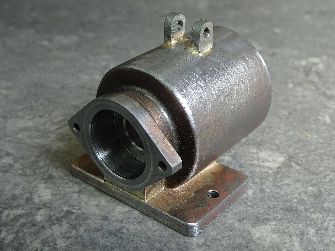
This is how it was left:


A pity, really because it was more than 1/2 completed.

Then, a few months ago, I had a PM asking me if I could get the engine to run and I had to admit that I had not even finished it. This pricked my conscience and so I got yet another power cylinder and flywheel from Polly and decided to try and make some more progress. The new cylinder did not look too promising, but in the end with the assistance of some JB weld I managed to get a reasonable object from it.


Dave
The Emerald Isle
 

Attachments

  • MyProgress1 (Medium).jpg
    MyProgress1 (Medium).jpg
    44.2 KB · Views: 809
  • MyProgress2 (Medium).jpg
    MyProgress2 (Medium).jpg
    55 KB · Views: 791
  • Cylinder (Medium).jpeg
    Cylinder (Medium).jpeg
    42.9 KB · Views: 806
Last edited:
A bit more done. When I make 'scale' models, I like to try and get a bit closer to the full size engine if the drawings aren't too accurate. In this case, the drawings show a plain flat plate across the back of the cylinder, whereas the full size engine has a speed regulator there. Although in my case it is not working, it does look a bit closer to prototype.


On full size, the pin is connected to a flat plate damper and the spring tension is set to control the engine speed by restricting return air from the power cylinder to the displacer if overspeeding. How effective this was I don't know, but in this small size it is just another area for air leaks to occur.

The piston, gudgeon block and Con rod have also now been made.


Dave
The Emerald Isle
 

Attachments

  • Backplate 3 (Medium).jpg
    Backplate 3 (Medium).jpg
    53.5 KB · Views: 765
  • Conrod, Gudgeon Block, Piston (Medium).jpeg
    Conrod, Gudgeon Block, Piston (Medium).jpeg
    41.5 KB · Views: 655
Hi Dave,
As you already know, I have one of these engines waiting in the wings to be made.

I have read about everything that could be read about these engines, plus how to get them running more efficiently.
People have come to the conclusion that for this type of model, the barbeque cleaning bricks are the best material to use for the large displacement piston.
I have got together all the bits required now, even some of these blocks.

If you want to try one, then this is the cheapest place on Ebay, and here is the item number (UK only) - 261510920858

If you do want to try some and can't get hold of any, then let me know and you should have some winging it's way to you.

John
 
Thanks muchly for the offer, John.
In a soon to be written future post, I will describe how I made a new displacer piston from stainless steel. If my effort doesn't prove to be any more successful than the original, I may go your route.

Dave
The Emerald Isle
 
The preferred material on the Alyn version is a crab meat tin filled with wire wool, I'm making a smaller version so will turn a thin one from stainless.

Dave if your cylinder still gives trouble then they are not too hard to fabricate.

DSC02800_zpsbzd63tvm.jpg
 
Good work there, JB. I reckon I've now got a good cylinder!

Polly supply a brass spinning for the displacer piston. Brass is not a good material for displacers so I'm told. One of the other problems of this design is the very small cooling water reservoir which heats up quite quickly. So after the resurrection, I decided to make a new piston from stainless steel to try and reduce one of the design flaws. It just so happens I had a suitable lump of stainless that had been lying idle for several years.


After rounding off the square lump of stainless, the embryo displacer was hollowed out. About 95% of the original metal was turned into swarf. When the inner dimension was reached, the can was put on a mandrel to finish turn the outside. I was aiming for a thickness of 10 thou, but by my reckoning it was about 8 thou and the top even less.
To prevent slippage of the can on the mandrel, I put a couple of turns of masking tape on the (parallel) mandrel. I thought this would be more secure than a taper on such a thin walled component.


A piece of stainless sheet was cut out and stuck to a superglue chuck to be thinned and have a shallow step turned to locate the can while the two parts were silver soldered.


Result: the original brass displacer weighed 93 gms and the new stainless one is 34 gms.
New and old displacers.


Dave
The Emerald Isle
 

Attachments

  • Displacer new 1 (Medium).jpeg
    Displacer new 1 (Medium).jpeg
    72.9 KB · Views: 705
  • Displacer new 4 (Medium).jpeg
    Displacer new 4 (Medium).jpeg
    87.9 KB · Views: 708
  • Displacer new 5 (Medium).jpeg
    Displacer new 5 (Medium).jpeg
    48.1 KB · Views: 759
  • Displacer new lid 1 (Medium).JPG
    Displacer new lid 1 (Medium).JPG
    71.3 KB · Views: 790
  • Displacer new and old (Medium).jpeg
    Displacer new and old (Medium).jpeg
    38.2 KB · Views: 741
The various links have now been made. In place of the supplied strip steel con rod and swinging link, I machined up new ones from some bronze pieces that came from that special store in the corner of the workshop.

When silver soldering the bushes in the top swinging link, I didn't trust myself to be able to do all three at once, so after each one was done, the part was put in the pickle, but I must have left the pivot end in it too long. I wanted to leave the bronze parts au naturel, but I will probably paint the swinging link and con rod now.

Also new drop links in place of those supplied. Screws were made up so that the links were not bearing on the threads, 7 and 8BA threads; the small dummy bearing adjustment screws are 9BA.
Swing arm, links, screws 1c (Medium).jpg

Dave
The Emerald Isle
 
It now comes for the time to line up the power cylinder on the platform. I had a trial assembly of the various links and rods and held the cylinder to the platform with toolmaker's clamps so that the con rod lay in line with the displacer rod. When happy with the position of the cylinder, a transfer punch through a bolt hole put a spot mark on the top of the platform. The first hole was tapped and a stud fitted. The cylinder went back on the platform to check it was indeed in the correct place, then the second stud hole was tapped.
There needs to be an air passage between displacer and power cylinder. The bottom of the cylinder had its hole drilled. To ensure that the hole in the platform was directly in line with the cylinder, I turned up a temporary punch that was quite a tight fit in the cylinder hole.


This was put in the cylinder hole so that the point would mark the platform when the cylinder was bolted back in place.


Hole drilled. Instead of relying on Hermatite or similar to make the seal 'twixt platform and cylinder, I used an O ring leaving it about 6 thou proud for compression when the cylinder was finally bolted up.


Dave
The Emerald Isle
 

Attachments

  • Cylinder line up 1 (Medium).jpeg
    Cylinder line up 1 (Medium).jpeg
    49.2 KB · Views: 723
  • Cylinder line up 3 (Medium).jpeg
    Cylinder line up 3 (Medium).jpeg
    45.8 KB · Views: 697
  • Cylinder line up 2 (Medium).jpeg
    Cylinder line up 2 (Medium).jpeg
    52.6 KB · Views: 630
I've had a trial assembly of the top end.

A few 'issues' have come to light, namely:
1. The con rod big end scraped the platform preventing full rotation of the crank.
2. There is a slight binding in the linkage.
3. The displacer links need to be remade longer by about 1/8" because they foul the con rod.

1. Was solved by shimming up the crankshaft bearing block with a 30 thou piece of steel Loctited to the bottom of the bearing block.
2. Was solved by slightly enlarging the stud holes in the bearing block so that there is some freedom to slightly pivot the bearing block. The whole mechanism seems to be reasonably free now, so I am hopeful the issue really has been solved.
3. The links have yet to be made. Hope I've got some more bronze pieces. Although the links were made to drawing length, my modified con rod is deeper than design and I did not allow for this when I made the original links.

Dave
The Emerald Isle
 

Attachments

  • Trial assembly (Medium).jpeg
    Trial assembly (Medium).jpeg
    34.4 KB · Views: 673
Looking good Dave, I've also been working on the linkages to mine when the shed has been cool enough. Are you hoping to have it running for the Bristol Show?
 
I made this engine last winter. I had a lot of trouble with air leaks but when I got that sorted out it took off. It would not run for long as the water boiled away quite quickly. I added a cooling tank that operates on the thermo-siphon principle.
 

Attachments

  • DSCN9684.JPG
    DSCN9684.JPG
    110.5 KB · Views: 465
New displacer lifting links have been made about 100 thou longer than the originals.

A trial assembly showed they cleared the con rod and swing arm during a full rotation of the crank. That clears up issue 3. I just hope there is sufficient displacer height now for full movement of the displacer can.


The replacement flywheel has been turned. There was slight pattern shift visible on the spokes and inside the rim, but at least the spokes are now equal thickness and opposite each other, unlike the earlier castings. Before machining, I sanded and filed the casting as much as I could then applied body filler as required to smooth out the bad bits. Easier to clean up now than after machining.


Dave
The Emerald Isle
 

Attachments

  • Links old and new (Medium).jpg
    Links old and new (Medium).jpg
    22.4 KB · Views: 716
  • Flywheel 2 (Medium).jpg
    Flywheel 2 (Medium).jpg
    54 KB · Views: 739
  • Links fitted 2 (Medium).jpeg
    Links fitted 2 (Medium).jpeg
    53.4 KB · Views: 533
Last edited:
Dave,
I had a problem with the flywheel in my casting set. The cast on balance weight on the flywheel, to balance up the crank, was missing.
A quick phone call had a new correct flywheel with me in a couple of days.
I see you haven't got one on yours.

John
 
The counter balance is in the back of the crank web, same on the Alyn version and full size. Or does the Polly one need extra weights?
 
John/JB
The first two flywheels had balance weights cast in, but what you see here is the third.
The Polly crank wheel is solid, hence the need for the flywheel balance weight.

What I have done is to carve out the back of the crank to leave a counterweight. I don't have a pic of mine at the moment, but I've copied the Anson engine shown here, hence no need for flywheel balance (he says hopefully).

Dave
The Emerald Isle
 

Attachments

  • 083 (Medium).jpeg
    083 (Medium).jpeg
    69.4 KB · Views: 622
I had the final trial assembly today. Everything feels free with no binding that I can detect.


There appears to be some compression, so it should be all systems go.

Perhaps the Hot Air cognoscenti here will advise me if my engine appears to have satisfactory compression.

Only one obstacle to prevent firing up: I went to look for fuel (tea light) but couldn't find any; a poor excuse, I know. So with some disappointment, I've stripped down the engine for cleaning and painting. I'll be back in a few days' time.

Dave
The Emerald Isle
 

Attachments

  • Construction complete 1 (Medium).jpeg
    Construction complete 1 (Medium).jpeg
    46.5 KB · Views: 616
  • Construction complete 2 (Medium).jpeg
    Construction complete 2 (Medium).jpeg
    45.4 KB · Views: 641
The engine has been painted and assembled so I can call it complete now. It's only taken 6-1/2 years!
I must thank Tom Jamboretz for prompting me a few months ago to get it finished.


It has been test run. A tea light does not give enough heat, but a Mamod fuel pellet is just the job. Video coming soon.

Dave
The Emerald Isle
 

Attachments

  • Complete 1 (Medium).jpeg
    Complete 1 (Medium).jpeg
    39.6 KB · Views: 581
  • Complete 2 (Medium).jpeg
    Complete 2 (Medium).jpeg
    46.3 KB · Views: 575
  • Complete 3 (Medium).jpeg
    Complete 3 (Medium).jpeg
    47.3 KB · Views: 600
Back
Top