Double acting Double Oscillator

Home Model Engine Machinist Forum

Help Support Home Model Engine Machinist Forum:

This site may earn a commission from merchant affiliate links, including eBay, Amazon, and others.

Brian Rupnow

Design Engineer
Project of the Month Winner
Joined
May 23, 2008
Messages
14,971
Reaction score
8,254
Location
Barrie, Ontario, Canada
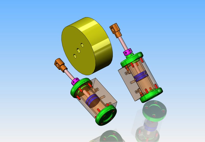
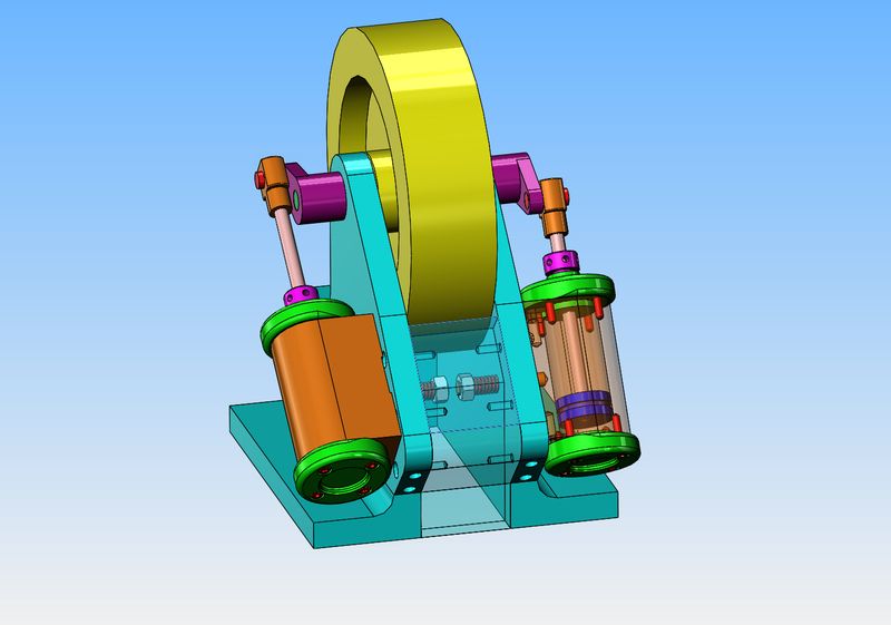
This is an engine which has always interested me. I think I first seen an engine like this posted by Tel from Australia. I was bored today, so I thought I would begin sussing out a design for one, built from bar stock. The one in this post has 1" bore cylinders with a 1.732" stroke. The flywheel is almost 4" in diameter (I am still trying to find a way to use those two steel rings I made up for the Kerzel. They didn't work out on the Kerzel, but they may do fine here.) Stay tuned, and as the design develops I will posted updated models.
QVFSto.jpg
 
Another 4 hours and we go from concept to an animation of the finished engine. I decided that a 4" flywheel was small enough that it looked out of place, so I bumped it up to 6" diameter.

If this new hosting site isn't allowing links to YouTube, just copy the link and paste it into your browser bar, then hit enter.
 
If I make the spacer transparent, you can see the 1/4" diameter pivot that is attached to the cylinder and passes thru a 1/4" hole in the angle. A stiff little compression spring and a 1/4" nylock nut ensures that the "face" of the cylinder body is held tightly against the face of the angle to avoid pressure loss, but still lets the cylinder pivot.
6KF3t1.jpg
 
If this was going to be a real "working engine" I would make the cylinders from cast iron or bronze, and make the angle from cast iron as well, because of the high wear factor at the point where the cylinder face pivots against the angle. Since it will only ever live as a "demonstration" engine, the cylinders and pistons will still be made from cast iron, but the angle will be 6061 aluminum. The green colored end caps will probably be made from brass for a bit of contrast. The flywheel is massive enough that I am considering making it from solid aluminum.
 
Velocette--I know that, but for the sake of what I'm doing here, it doesn't have to self start. It will run smoother at low speed with the crank at 180 degrees .
 
"" It will run smoother at low speed with the crank at 180 degrees".
Whoa!! I don't think so 2 power strokes per revolution opposed to 4 power strokes per revolution.
That heavy flywheel and 90 degree cranks it will run incredibly slowly
I am quite aware that you probably knew that it would not self start.
The posting was an OBSERVATION only.
Eric
 
Velocette---I was wrong.. I had suggested that the engine would run "smoother" with better balance if the crankshaft was set up for 180 degrees. I was wrong. With the crank throws at 180 degrees, you only get a power stroke twice in one full revolution of the crankshaft. With the crankshaft set for 90 degrees, you not only get self starting capability, you also get a power stroke every 90 degrees, so consequently the engine should run much smoother and slower with a 90 degree crank. Thank you for showing me the error of my ways.---Brian
 
Last edited:
Velocette--I know that, but for the sake of what I'm doing here, it doesn't have to self start. It will run smoother at low speed with the crank at 180 degrees .
Hi, Brian. At very low speed, say about the 30 rpm mark with no load, the the lack of balance might well show, but at that sort of speed I would think variations in friction and leakage would have just as much of an effect on smooth running. At a normal low speed, I think you would be better off at 90° especially with o-rings on the pistons: the torque will be much more constant with four small power pulses instead of two big ones. At higher speed (the bits become blurry at 200-250 rpm) there would indeed be a bit less vibration at 180°, though there would still be a rocking couple. 180° is very abnormal for a double-acting twin - with good reason?

I would relieve the port faces round the pivot pins.

For cylinders of that size, I would use bigger pivot pins.

Crosshead guides are almost always neglected in model oscillators, but they do take the side thrust off the glands.

Put outboard cranks (could be just followers) and bearings and you have yourself a paddle-steamer engine!

Edit: This post was sitting on my screen for several hours before I finished it, and I did not notice the more recent intervening posts.
 
Hi Brian
Never once was I in doubt of your skills an abilities at small engine design and construction.
As usual I will take an alternative view on things to promote a debate on ideas.
Eric
 
This morning I priced out the material to build this engine. It was going to cost $155 for all of the material except the bearings. $50 of that was for brass, so I did a very deep scrounge of every bit of brass and/or bronze I have tucked away. I still had the top knob of that 50 pound bronze government weight that was used to check scales, and one lonesome piece of 2" bronze round stock x about 7/8" long. That actually yielded enough bronze to make four cylinder end caps. I have lots of little pieces to make the piston rod ends from. As soon as I have posted this, I'm heading out to buy the rest of the material.
DcA6B2.jpg
 
In the picture you see $105 worth of material. $25 for the 2" diameter cast iron and $80 for the aluminum angle and 2" thick bar. I worked for about 3 hours to salvage $50 worth of bronze that I had laying around my shop.--Not very sound economics, but these small engines never make sense from a $$ point of view. I have finished turning the two cylinder end caps for the non rod ends, and I have the material for the other two cylinder caps up in the lathe. That will be tomorrows job.
mtzJum.jpg
 
"... these small engines never make sense from a $$ point of view...

I wholeheartedly agree.

Care to use whatever term you like, but this hobby is toy making. Call it a scale model if you want. It's a toy, like a Hot Wheels car or a model airplane. These have no real industrious purpose. At best, they can be a teaching tool. There is nothing about this hobby that's economical or practical because toys aren't supposed to be practical. That's what makes them toys.

Doesn't mean it's not an enjoyable pastime. It's just the price we're willing to pay for the entertainment of the pursuit of the hobby. Some people will pay thousands upon thousands of dollars for the perfect model. Other scrounge up that they can. Personally, I have a dollar limit that I can justify. To everyone else, I'm wasting money making toys.

...Ved.
 
Brian,
It's a bit late, but you can download plans for Elmer Verberg's #9 H Twin from http://www.john-tom.com/html/ElmersEngines.html. You might like to have a look anyway. This was a club challenge at my local model engineering club last year and a fun build for novices like me.
Your plan looks interesting and I look forward to the build.
John B
Australia
 
This morning I finished machining the cylinder end caps, except for the counterbored holes for #6 shcs. I managed to break my 1/4" reamer. It started to squeal a bit and then "grabbed" in the bronze and twisted off. That reamer owes me nothing. I've had it for 10 years now, and it has reamed a thousand holes. It was getting dull anyways, and I don't think you can sharpen a reamer without it ending up "undersize". If you wonder why the counterbore in the non rod end caps is so deep, it's because the one piece of bronze I scrounged up had a deep drill hole at that end, and I had to go deep enough to get past the drilled hole. It won't affect the way the engine runs, as it's just a cosmetic feature anyways.
bqEzXe.jpg
 
Cylinder end caps are finished, and I'm done for the day. Each end cap has a milled pocket to let air into or out of the cylinder. There will be a few holes in the cylinder body that connect to these pockets, and as the engine oscillates the appropriate holes will be covered and uncovered.
ITxgtZ.jpg
 

Latest posts

Back
Top