Inspiration for new air motor

Home Model Engine Machinist Forum

Help Support Home Model Engine Machinist Forum:

This site may earn a commission from merchant affiliate links, including eBay, Amazon, and others.
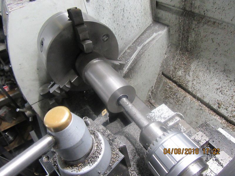
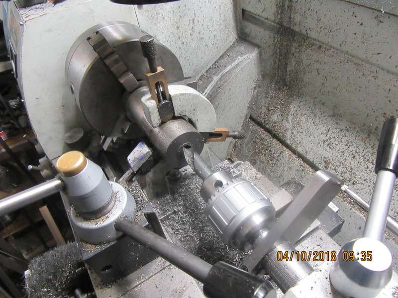
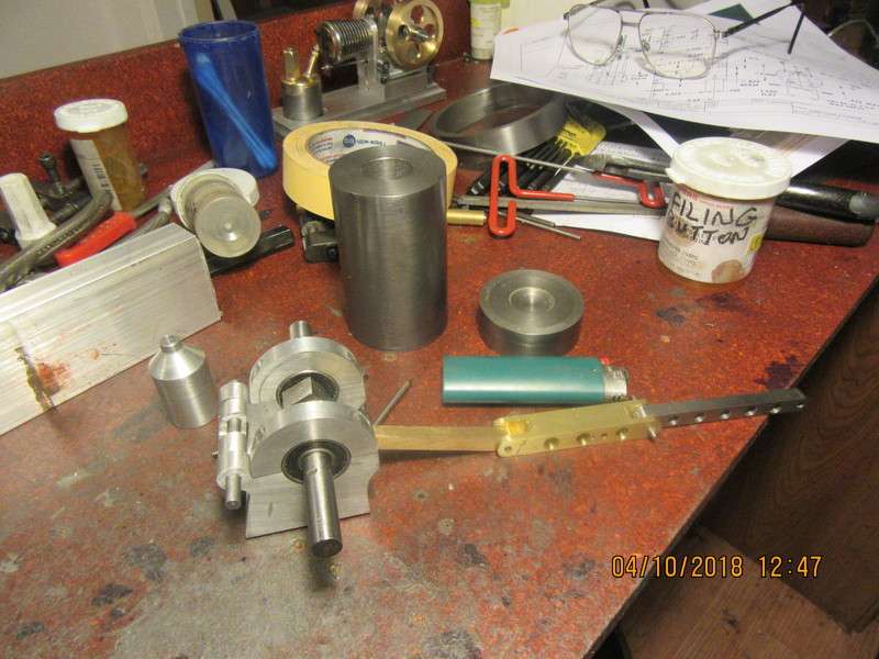
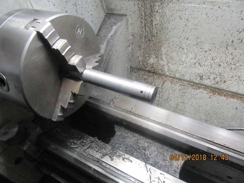
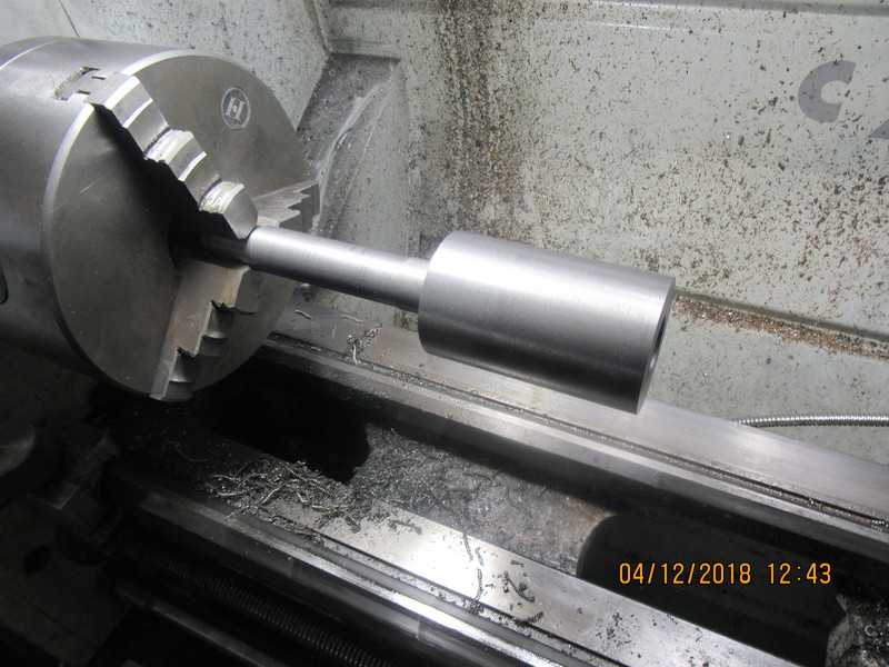
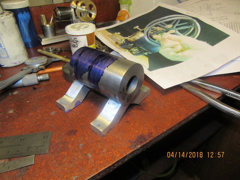
This afternoon I made a start on the cylinder. A great big scaly old piece of cast iron, with a finish on it like a ponderosa pine. It was about 2 3/8" diameter and had came right from the foundry that cast it that size. I used a brazed carbide tool to bring it down to within about 0.010" of finished size, then changed to a HSS tool for the final cut to bring it down to 2", running about 400 rpm. I don't want to take it out of the chuck, so I will move my tailstock back out of the way and rig my steady rest to support the end opposite the chuck while I drill/bore/ream the 7/8" hole in the center.
kNX7n9.jpg
 
Brian,
Some of the cast iron I have machined over the years were the same, hit with the ugly stick, and found to be some of the best machining after getting under the scale.,
Looking good, just following along.

Cheers
Andrew
 
HoooYahhh--it goes round and round and nothing crashes. There isn't a lot of clearance anywhere, but a miss is as good as a mile!!
DI7ikQ.jpg
 
I'm getting to the point where I have to be careful of what gets done next. The cylinder is still up in the lathe, and before I tear down the set-up I will put my steadyrest on the end opposite the chuck and drill/ream it to 7/8" diameter. Since this engine will have a ringless piston but still require a "very good" sliding fit, I will lap the piston into the cylinder. This requires that I hold the piston in the chuck, and with the lathe turning slowly I use either diamond paste or aluminum oxide 600 grit, and hold the cylinder by hand, slowly sliding it onto the piston in a back and forth movement. This is a "by feel" fit, and it's not uncommon for it to "grab". When it does, you want to be able to let go of the cylinder very quickly. I used this method on the two cycle engine I built, and it worked perfectly, but is more than a little scary. As you can see in the attached picture, there are three flats to be machined into the cylinder, but I won't put them on it until after the piston fitting is over with. I want to do that while the cylinder is a simple cylindrical shape, so nothing on it can grab my hands and wind me up in the lathe.
oaR6t1.jpg
 
The cylinder has the steady rest on it to keep it from flopping around with so much "stick-out". The hole is being drilled in stages, first a 5/8" drill, then a 3/4" then a 27/32" drill, and after that I will bore it to 0.875".
ZtsEHt.jpg
 
So---We have a cylinder and a cylinder head. I didn't use the reamer at all. I drilled it out to 27/32" and finished up with a hefty brazed carbide boring tool. The finished bore as of now is 0.873". The best thing about this cylinder is that it was free. Nah, I actually paid for it on some other job and the 7" long piece of cast iron was a left over . Next up will be to machine a piston.
40EiP6.jpg
 
After honing the cylinder with my variable speed drill and a 3 stone brake hone, then lapping it with 600 grit aluminum oxide paste and one of my new laps, the bore is setting right on 0.874" (near as I am able to measure it with a telescoping bore gauge and a micrometer). I think that rather than lapping the piston into the cylinder, I will make an external lap and bring the piston down until it matches the cylinder bore.
 
This afternoon I made the piston. It's so new in this picture that it hasn't even had the tit machined off the end yet. Tomorrow I will decide exactly how I'm going to fit it to the cylinder, and will face it to the correct length, getting rid of the tit in the process.
SdX6Oi.jpg
 
I think I may have to go to larger flywheels. The flywheel input to the sliding piston is at a 1:2 mechanical disadvantage. That means that the flywheels need to be considerably larger than on a "normal" engine where the flywheel ratio to piston travel is a 1:1 ratio. I have looked at a number of videos of this engine as a flame-eater, and they all have larger flywheels. My original thoughts were to have a 4" o.d. flywheel. Now I'm thinking of larger diameters. A 4" nominal diameter pipe has an actual o.d. of 4.5" (dotted outline on drawing). I have to think on this for a bit, and as I have other parts of the build to complete, I have time to roll this idea around in my head a bit.
alfWXY.jpg
 
I had the four jaw chuck up on the lathe, and decided to see if there was anything on this engine which would require the four jaw. Sure enough, the elliptical can still had to be machined, so that's what I did this morning. You can see it setting in place on the crankshaft. Now I change back to the 3 jaw and fit the piston to the cylinder.
t8VyVi.jpg
 
I have achieved an almost perfect fit between the piston and the cylinder. It doesn't show in the picture but the entire piston has taken on that uniform dull finish that comes from lapping. The piston will slowly fall thru the cylinder under the force of gravity, but if I put a hand over the bottom of the cylinder the piston stops. I have to go and keep an appointment now, but when I get back I will explain a bit more about how this was done.
S1Q7Qm.jpg
 
Here's a little story on how I sized the piston to the cylinder. In shot one, you see the piston, a short piece of threaded rod with one end turned to fit into the piston where the con rod goes, and a hole in it for the wrist pin. The shaft laying in line has the end turned to fit inside the piston, with a shoulder on which the piston can set, and a 5/16-18 tapped hole in the end. The turn down at the other end of that piece of shaft is not needed.--it just happened to be there. In shot #2 the threaded rod is mounted in the piston. You can't see the wrist pin, but trust me--it's there. The retaining set-screws that hold the wrist pin in place are tightened down--I don't want the wrist pin to drift to one side and score the cylinder wall. Shot #3 shows the piston tightened onto the piece of shaft, with the piston skirt setting on the register. Shot #4 shows the shaft with piston mounted in the lathe chuck, and picture #5 shows the cylinder started on over the piston. The piston is coated with #600 aluminum oxide paste. The piston diameter has been turned to a diameter that just starts to fit into the cylinder, but not quite. (About .001" interference). It is important that the shaft have an outside diameter about 0.050" less than the outside diameter of the piston. we only want to lap the piston---not the shaft supporting it. The lathe is ran at about 60 rpm, and the cylinder is held by hand and slid back and forth over the piston. making sure that the piston extends out of the cylinder about 1/2" at both ends of the stroke. At first this requires a strong grip, but the aluminum oxide paste works very quickly and it loosens up quickly. This is where you want the cylinder to be simply round with no features, so that if it "grabs" you can quickly let it go.
VUQ5Wa.jpg

QfSNza.jpg

yipkVf.jpg

lg4tLk.jpg

xrWFB7.jpg
 
Dug deep into the Rupnow fortune today and ordered a set of 5" cast iron flywheels from Martin Model and Pattern for this new engine. I have a ridiculous number of home built engines with every conceivable type and style of flywheels on them, all made by myself except for the ones on my Rockerblock engine, which I had water-jet cut. Figured it was time to spend a bit of money on something "store-bought".
 
This is something you may find interesting. Due to the way this engine is laid out, I can't have a normal tappet riding on the cam. Instead, the bronze shaped cam follower fits around the cam and is pinned to the 3/16" rocker shaft, as is the yoke which will operate the air valve. As the crankshaft rotates, it will move the cam follower in a rocking motion, that will in turn cause the end of the Y shaped piece to move up and down, to operate the air valve.
t0Ly0h.jpg
 
The solid model has been updated to show it with the new 5" diameter flywheels I have ordered, (I think they are much better in proportion than the previous 4" diameter ones.) In one of the models the near side flywheel is hidden so you can see the cam follower and the Y shaped lever that controls the air valve.
imMPTE.jpg

LHmBqP.jpg
 
I was flying right along, beginning initial assembly. Then I opened the box with my #6-32 taps in it. The bottoming tap was broken off (I remember doing that and had meant to replace it). The blind holes for the taper tap are only 0.470" deep, and the taper tap bottoms out before it starts to cut a full size thread. (these are the bolts which hold the support feet to the cylinder.) There is nowhere in town to buy a replacement tap.---Ahh bugger!!! Oh well, I've done enough for today anyways.
5YNUDQ.jpg
 
Nice work Brian. Any chance you will pack up some models and come over to Detroit next week for the NAMES show. I'm sure a bunch of us would like to see them and get to meet you.
 
The ball nosed endmill does add a very nice feature when it is used. What doesn't add a nice feature is when you misread your own drawing and put two counterbored holes in the wrong place. Damn, I hate it when I do that!!! Fortunately, the tops of these counterbored holes will be hidden under the air manifold. So--clean it up, set it on a piece of cardboard, and fill the two offending holes with J.B. weld. When the J.B.Weld sets up, I will rebore the holes 0.100" inboard of where they currently are.
5YsbZ1.jpg
 
Totally bummed out here. Two solid days of ice storm. I'm even tired of machining things. However, I did accomplish one thing today. The pivot bracket that fits onto the open end of the cylinder has to be silver soldered together in a jig. The bracket is brown in color, made from 3 separate parts. the jig (green) was made from two pieces of scrap out of my bin. The three shcs in the jig are an exact copy of the bolt pattern in the open end of the cylinder.
EqX92Y.jpg

7YzQ54.jpg
 
Back
Top