Head cold from Hell and maybe a Stirling engine

Home Model Engine Machinist Forum

Help Support Home Model Engine Machinist Forum:

This site may earn a commission from merchant affiliate links, including eBay, Amazon, and others.
What an ignorant wee piggy that gusset plate is turning out to be!! The piece of stock I have to make that from is just slightly larger than the finished part will be. My largest drill is 1" and the radius on the gusset is 1". There is really no good way to hold it in the mill vice to use my boring head. It looks like it will be a faceplate job. I will have to think about this one some more, and see if I have some scrap to make the brown colored fixture from.
qBOt6E.jpg
 
Brian
I think you have made a basic mistake with your design
The Hot air engine works on the expansion and contraction of gas due to heating and cooling
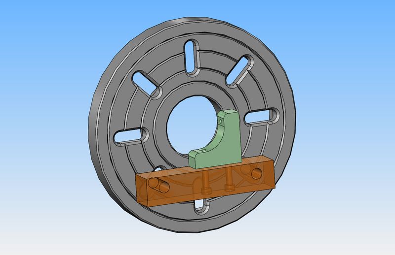
I Think You have the Cooling Fins on the wrong side of the Plate which has the port going to the power pistons.
I use Berocca Viatmin Tubes for the Displacer Pistons ( 1 inch Diameter ) or fabricate from alluminium Tube . Hot end caps I form from Copper Sheet and Hi Temp Braze to End of Hot Cylinder
Use ball bearings with no oil just WD 40 for Lube
Piston Rod bush make 4 x Diameter Long for any type of Gas Seal . Cast Iron is best ( self Lubricating )
Piston Rod is normally 1/8 " drill rod polished to mirror finish to reduce friction
Power piston is cast Iron and run about 1/16 wall thickness
Friction and Gas seal is Everything
All cylinders are Spigot and Socket and use Thread Tape rolled into a twine to Seal . and a bit of Silicon sealer to hold in place
Use WD 40 to lubricate
These things wear out quickly as most do not use a cross head piston to take side load of piston rod and Leak air / gas
I use a cross head piston on my designs to prevent this

014.jpg
 
It works both ways, ie fins north of plate or fins south of plate -- see the Moriya plans I posted a link to earlier. I prefer the way Brian has done it, and Moriya, because the plate then acts as a heat sink to stop heat form the hot end traveling straight into the finned area of the cool end. But plenty of other engines work the other way. The exact port location is not critical because it is the pressure going through the port that pushes the power piston down its bore and pressure is virtually constant through the whole system, depending on where the displacer piston is at and how much air is in contact with the heat source vs in contact with the cooling muff.

One advantage of having the cooling fins on the other side of the plate, as in the engine in your (Goldflash) pic is the connecting rods can be longer, giving less conrod angle, giving greater mechanical advantage and less inclination for sideways forces to jam the piston or guide rod. But again, plenty of engine made the other way work just fine too. So its six of one and half a dozen of the other.
 
What an ignorant wee piggy that gusset plate is turning out to be!! The piece of stock I have to make that from is just slightly larger than the finished part will be. My largest drill is 1" and the radius on the gusset is 1". There is really no good way to hold it in the mill vice to use my boring head. It looks like it will be a faceplate job. I will have to think about this one some more, and see if I have some scrap to make the brown colored fixture from.
qBOt6E.jpg

Or you could clamp the job to the faceplate using a clamp and bolt, the standard type used to clamp a job down to the milling machine table.
 
For the hot caps I use stainless steel or glass as they are poor heat conductors and like to machine a heat dam into the hot cap when possible. It seems to make for a longer running engine
kind regards
 
Brian
Not to fill up your project post but here is a picture of the engine my dad picked up a while ago.

Like how they used wood as the center of the flywheel.

IMG_2346.jpg
 
And here's an update on whats happening today. I trimmed my over-thick piece of material for the gusset down to 0.742" (that is the width my once sharpened 3/4" endmill cuts to.) The layout lines on the piece show the cut lines. The base is finished, setting in the background, with two likely candidates for the fixture which will be made to mount the gusset plate onto the faceplate for boring. There is no work at my across town office tomorrow, so I should be able to finish the gusset and maybe the last piece of frame plate that the cylinders mount to.
ZXmELD.jpg
 
And for those of you who like to see set-up pictures---Here we have the 2" diameter hole bored thru the gusset plate. I used my longer boring bar to clear the bolts which are holding the gusset fixture to the faceplate.
LNZ0m1.jpg
 
All of the aluminum frame pieces are finished. Even though there was a fair bit of extra work carving the radius in the gusset, I like it. Faceplate work is something I do very little of, so it was kind of fun.
lPZpfs.jpg
 
I scrounged around in my brass drawer, looking for enough brass to make the bearing stands from. All I had that was big enough to get two pieces out of was the last of an aluminum bronze bar I've been using up. Damn, that's miserable stuff!! It's as hard to machine as mild steel. I'm glad that these two stands will be the end of it. I can't even remembered why I had it, but I will make it a point to not buy any more.
 
Looking good Brian. Looks like the whiskey did the trick :D
 
Here we have a couple of rather poorly lit pictures of the bearing stands. One picture is an "in process" shot of the stands being reamed "in line" and one shows them assembled with a pair of very tiny 3/16" ball bearings from the r.c. hobby shop. I will take the side seals off the bearings and wash them out with laquer thinners to remove any grease. I still have to round of the tops of the stands.
rUFzNJ.jpg

IfUMZ4.jpg
 
Not a great deal of progress today, but some. I rounded off the tops of the bronze crankshaft stands and they are finished. I took the seals out of the miniature ball bearings and washed all the grease out of them.--This sounds rather counter productive, but it is what is recommended for Stirling engines, as it cuts down on the rolling friction.
wANIBa.jpg
 
I have almost reached the point in this engine build where everything "generic" in nature is finished, except the flywheel and crank throws. The crank throws will be made from aluminum. Tubal Cain made the flywheel on his Stirling engine from cast lead. I was going to machine my flywheel from mild steel, but mild steel just doesn't have that visual "pop" that I like so much. So--Today I stopped in to Barrie welding and checked out their shorts rack for a suitable piece of brass or bronze. I found this one for $18, and I will use it for the outer rim of the flywheel and machine a center from aluminum. Once this bit is done, everything that follows will be pure Stirling engine, courtesy of Moriya fans.--Plagiarism at it's very finest.
Ikw6fq.jpg
 
Todays offering to the machining gods--A pair of crankshaft "throws". Tomorrow, if I'm lucky, I'll finish the two piece flywheel and maybe the connecting rod journals. After that it will be hard and heavy into dedicated Stirling parts.
OegSCU.jpg
 
It's a flywheel!!! If I had five 5/8" holes drilled in the web and a couple of finishing passes on the sides, it would be a beautiful thing. I don't get silly and try to shrink the rim on. I completely finish the bronze ring first, leaving about 0.010" on each side and on the o.d for final clean-up passes after assembly. I machine the aluminum for a "damned close" into the bronze ring, taking the last few passes on the aluminum at .0005" until the bronze ring will just begin to slide over the aluminum. Then its get the #638 Loctite out, slather a bit on, slide the ring into place, and leave it set until tomorrow for finishing.
WwNOkN.jpg
 
So there we have it.--a beautiful thing. Everything that is not directly related to Stirling engine parts is finished. This week I hope to start on the parts that will make this a Stirling engine.
JYsJes.jpg
 
Today I got confirmation that the baby Jesus still loves me. I was tapping #6-32 holes through the aluminum "crank throws" for grub screws to hold them in position on the crankshaft. The tapered tap was pretty "oinky" going in, but lots of oil and a very gentle hand got both pieces tapped. Since the center hole is only 3/16" in diameter, I had to run a bottoming tap through after the tapered tap to have a complete thread. The bottoming tap snapped off with a piece about the size of a babys fingernail still above the surface. I immediately thought "Oh Oh--I'm going to have to remake this piece". I went out to my garage and brought in an assortment of pliers, and VERY gently grabbed the little piece of tap still visible and VERY GENTLY worked it back and forth----And it came out!!! That happens so rarely for me (the fact that it actually came out) that I thought it was worth posting about!!
 
This was a piece of "had it anyways" brass that is in process today. Normally I would buy a piece closer in diameter to the finished part here, but when you're dealing with "had it anyways" material the rules are different. This is destined to become the "power cylinder" on my engine.
yjS1SS.jpg
 
Back
Top