Model Compressor---Maybe

Home Model Engine Machinist Forum

Help Support Home Model Engine Machinist Forum:

This site may earn a commission from merchant affiliate links, including eBay, Amazon, and others.
Brian,
Would it not be easy to fit a check valve in the top of the green tubing, will be watching as usual.

Cheers
Andrew
 
In small displacement pumps like this it works better to have the valves as close as possible to the cylinders.
 
So, I have all the reclaimed "odds and sods" from the auto-reversing mechanism that I never got to work. I can re-use two of the bras gears, the dark steel gear, the large pulley and the round part with three smaller holes in it at 120 degrees apart. I will also re-use the rack and flatbar, but not on this project.
bjKeqt.jpg
 
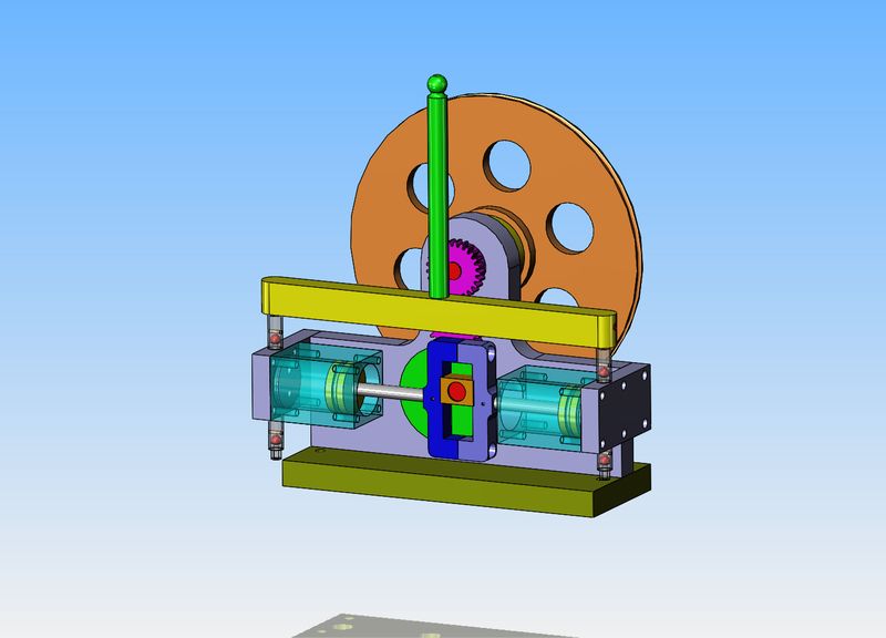
Time to ask a question. I have looked a great number of Scotch Yoke engines on the internet, and all of them are single acting. This doesn't mean that there are non out there, but if so I haven't found any. Ergo, there may be some very good reason for that. It may be that there is too much bending moment imposed on the small diameter piston rod when the rotating member is at the extreme bottom or top of the slot in it's orbit. If I change my design to single acting, where I don't have to have a seal around the rod at the end closest to the center, I can run a much more robust rod. I could also dispense with the inboard cylinder caps and half of the valve bodies. It would pump air at only half the rate of the original design, but then again it's only work would be blowing up a balloon. comments please.
 
Brian
I used to help build and sell CNG compressors 3-4 stage up to 750 hp 3600 psig discharge. I remember one company that spent millions of dollars developing a small 4 cylinder 4 stage compressor using scotch yoke system and ceramic valves for a home refueling . We ended up with a few samples that ended up as curiosities in the corner.
You already have figured out how to design and make automatic inlet valves for your minature engines. so if you have those for letting the air in then all you need to do is reverse the design for the discharge valve.
What pressure do you need for a balloon and what volume
with a simple compressor you might only get 30-40% volumetric efficiency to let the air out
Or use as really cheap home handy man compressors use, basic reed valves
 
Hey Brian, are you planning on using a bearing inside of the slotted Piston rod to help reduce friction?

I also can't help to notice that the movement of the slotted piece kind of looks like an auto reversing mechanism. it travels back and forth in the horizontal direction, but stays stationary in the vertical.
 
I like slinky treadmills....

I've written some arduino code in the past that controlled a steam throttle via a stepper motor. It measured shaft speed then opened and closed the throttle as required. It wasn't a full PID control, but it got the job done for my case.

...Ved.

Appologies for the OT , but a cool project would be a steam engine with corliss valves and have an arduino control the valve opening .
Kinda like a "fuel injected " version of trhe steam engine .


Brian , lovely project as usual , I'm watching :thumbup:

Pat
 
Time to ask a question.

I see no reason for not making it double acting if you want, other than that it is completely unnecessary. As, for that matter, is most of what we do here.

I recommend a die block or slipper between the crankpin and yoke.

If you go single acting you could have it done by Thursday.
 
Well, this is getting asinine!! I stopped by my material supplier and priced a foot of 1 1/4" square brass for cylinders. Quoted price was $55.00---Too rich for my blood. So--I bought a foot of 1 1/4" square cold rolled steel and a foot of 6" x 1/2" aluminum, and that cost $40.00 I may have to take up a second career as a belly dancer or something to pay for my hobbies.
g16t7Y.jpg
 
Okay--A few changes. Biggest change is that we are going to aim for single acting. However--I have left sufficient room to add rod end caps to the cylinders and make them double acting if I have to. I have split the "yoke" into two halves that are bolted together. One half is threaded #8-32 and the other side has a #8 counterbore. I have added a bronze slider to the yoke shaft as was suggested by a forum member. The cylinders have a "thru bore" now instead of being blind on one end.
Pqu7pT.jpg
 
Just thinking on deflating the balloon, you have a large pulley wheel at the rear, could a pin be located on this on the outer part, that would trigger a "dump valve" basically a large bore pipe with a spring shut ball valve. The pulley rotates, the pumps fill the balloon, then the pin in the wheel opens the valve for the balloon to deflate, yould need a slightly larger bore to allow the air to escape and the balloon to go flat. But it wouldn't require much modification to the design you have for it to work?
 
I like your design so far Brian. It should be fun to build and fun to operate!!
I would like to suggest that you make the sliding block at least as tall as it is wide, or maybe a bit taller, to avoid any tendency to try and cock in the slot. Even if the clearance is small the tendency is there...

:thumbup:

Pete
 
Every project has to have a beginning. This is really too soon after my last project, the twin reversing steam engine, but I was bored today, and you know what that does. I bought my 1 1/4" square stock for the cylinders in a 12" length, and I just have enough clearance to get in over-top of the stock with my chuck and edge finder. I couldn't do it with the stock setting in my vice, so it is setting flat on the mill table held in place by a setting angle and c-clamp. I will drill both ends with a small centering bit, then saw the cylinders to about 1/16" longer than finished length on my band saw. The cylinder bore has to be done in the lathe with my 4 jaw chuck, and that small center-drilled hole will be used for my centering set-up in the lathe.
HmIkkx.jpg
 
I think you should make the check valves with glass bodies. It would be fun to watch them in action.
 
I could use a bearing, but the sliding block in my last 3D model will probably work better. The problem with using a bearing or any other round pin, is that you only get a "line contact" with the yoke. A sliding block distributes the load over a greater area.
 
This morning I carved out a pair of cylinders from the cold rolled steel square stock. I still have to clean up the bores a little bit with a 3 stone brake hone, but they are basically finished. I will hone them, then machine the pistons for as "airtight" a fit as I am capable of. A very finicky fit.--Tight enough to seal air but loose enough to slide through with a very light finger pressure.
0WyDsB.jpg
 
Each cylinder has it's own piston now. The pistons are a lapped fit into the cylinders----as much as it can be. Lapping aluminum is a bit like trying to polish a turd.--It's too soft to lap properly. The pistons are at a point where they won't fall through the cylinders, but can be pushed through with a finger. I'll find out how good the fit really is when everything is finished.
udsHkr.jpg
 
Today was yoke day. Nothing too exciting, just milling, drilling, sawing and tapping. The piece of 1/4" rod stuck through the yoke is going to become the piston rod. I still have to square up the inside corners.
OuN0nD.jpg
 

Latest posts

Back
Top