Auto reverse mechanism

Home Model Engine Machinist Forum

Help Support Home Model Engine Machinist Forum:

This site may earn a commission from merchant affiliate links, including eBay, Amazon, and others.

Brian Rupnow

Design Engineer
Project of the Month Winner
Joined
May 23, 2008
Messages
14,969
Reaction score
8,250
Location
Barrie, Ontario, Canada
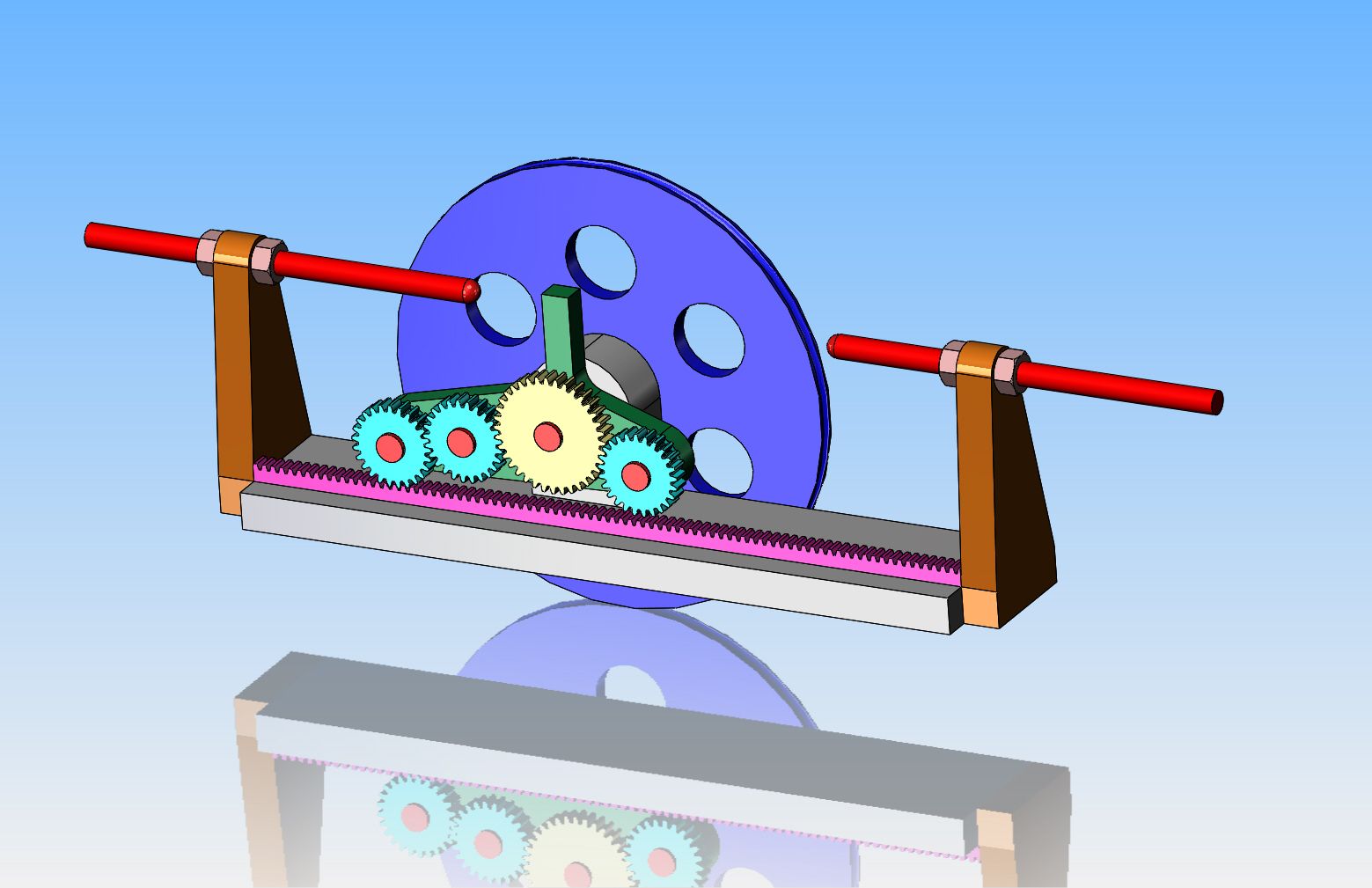
I am getting a yen to machine something, but not an engine. I am somewhat intrigued by mechanisms that have an "automatic reverse" function to them. Not just a simple function like reversing gears, but more like something that moves along a short track, stops at the end of travel, then reverses movement and moves back to the original starting point and then repeats. The power source for this would be one of my many small engines. I have googled "reversing mechanisms" and there is a great array of articles posted about this. Of course, I want it to be something with a considerable "WOW" factor to it. I have the capacity to make spur gears here, but not internal gears nor funky gears like you see on a mangle.(Which is super neat.) The biggest problem I see to a mechanism like this is that when it gets to the "turnover" point, if it has to shift a lever to go into reverse it will probably just "hang up". The actual mechanism which moves something along can be a threaded rod with a threaded follower that reverses rotation, or a rack/pinion drive, even possibly a flat belt drive that shifts from a clockwise rotating pulley to a counter-clockwise rotating pulley. The big deal is that it has to do this without human intervention. I don't have the capacity to make a double reverse thread like you see on "level-wind" fishing reels. My tools are strictly limited to a manual lathe and a manual mill and a full set of 24 pitch gear cutters. I will have no problem designing whatever it is that I do, it's more the fact that I have to figure out exactly what I want to do. This is a wide open game, so if you have a good suggestion or a link to this type of mechanism working, by all means go ahead and tell me about it.---Brian
 
Would something like this be what your looking for? If the pictures don't show you how it works I'll try to explain.

20170805_191200.jpg


20170805_191150.jpg


20170805_191138.jpg
 
Nautilus29--I see that it is a double roller chain with a slider block attached to one of the links.--Tell me more please.
 
In the second picture down you can see that the slider block had a bearing bolted into the end of it. You can see that the bearing is inside of a vertical slot of another block(I'll call this the arm). In the first and 3rd pictures you can see that the arm is sitting freely on a shaft and able to move back and fourth on that shaft.

So what is happening is the slot allows the bearing(attached to the slider block) to move up and down as it swings round the chain, but it does not allow side to side movement. Let's say that the chain moves clockwise. When the slider block is on the top of the chain it pulls the arm towards the front of the picture sliding on the shaft. Then as the slider block rotates around the gear to the bottom of the chain the bearing is allowed to move down in the slot and then pull the arm back towards the top of the picture. This action will happen over and over again with the chain only ever rotating in one direction, but the arm pivoting back and forth on the shaft as it follows the bearing.

Let me know if I didn't explain it very well. I can take more pictures if needed.
 
This is a rough idea of how a spring loaded toggle would work. The tension spring will always try and make the toggle rest either as shown, or rotated to be against the other stop, with a small dead spot when the toggle is perfectly vertical between the two positions. Any force applied in direction A would make the toggle swing up to the dead spot (vertical) and then a bit more force will make it snap over to the second position. This "swing" of the toggle would have to be used to move a set of tumbler gears into position to reverse the mechanism. It's not a great drawing, but I think it shows what I'm thinking of.---Brian
http://imageshack.com/a/img923/3755/hu0oJO.jpg
 
Hi Brian
this call and known as "an over center spring" every mechanical
relays use this set up
cheers
 
Brian, How about a small friction drive transmission. Small roller driving a disc, depending on which side of the axle the drive tire is on controls direction. Wouldn't take much to shift back and forth and the amount of travel also adjusts your speed. Further from the axle= lower gear ratio.
 
Okay!!--I followed George's instructions, and it worked. The design isn't finished yet, but it's getting close. I would prefer to have the rack setting still and the pulley and gears moving back and forth, but that means I would require some kind of tensioning device on the drive to the large pulley.
Q6VtSc.jpg
 
Back
Top