1/4 Galloway Hit and Miss engine

Home Model Engine Machinist Forum

Help Support Home Model Engine Machinist Forum:

This site may earn a commission from merchant affiliate links, including eBay, Amazon, and others.
Now that the head is mounted, I don't want to mount the pushrod brackets until I have the Rocker Arm Support Bracket mounted, to ensure that everything is aligned. I could move the pushrod brackets slightly if needed.

This is another example of using reality and not just the drawings, even though I try to make sure the two match.

Starts with the casting, I used the belt sander to remove some of the casting marks and then into the lathe.

IMG_4488 by Mark Savoca, on Flickr

IMG_4520 by Mark Savoca, on Flickr

Once faced, I center drilled so I could bore out the inside.

IMG_4522 by Mark Savoca, on Flickr

IMG_4524 by Mark Savoca, on Flickr

IMG_4527 by Mark Savoca, on Flickr

Next I built a simple arbor to hold the bracket so I could machine the outside.

IMG_4528 by Mark Savoca, on Flickr

The live center gives support and pressure to stay on the arbor.

IMG_4532 by Mark Savoca, on Flickr

IMG_4533 by Mark Savoca, on Flickr

I used a small sanding drum to clean up the edges.

IMG_4537 by Mark Savoca, on Flickr

IMG_4552 by Mark Savoca, on Flickr

Next, because there is not flat sides to clamp, I created a small plate the held the bracket square.

IMG_4554 by Mark Savoca, on Flickr

Drilling for the rocker pin.

IMG_4557 by Mark Savoca, on Flickr

Machining the slot for the rocker arm.

IMG_4563 by Mark Savoca, on Flickr

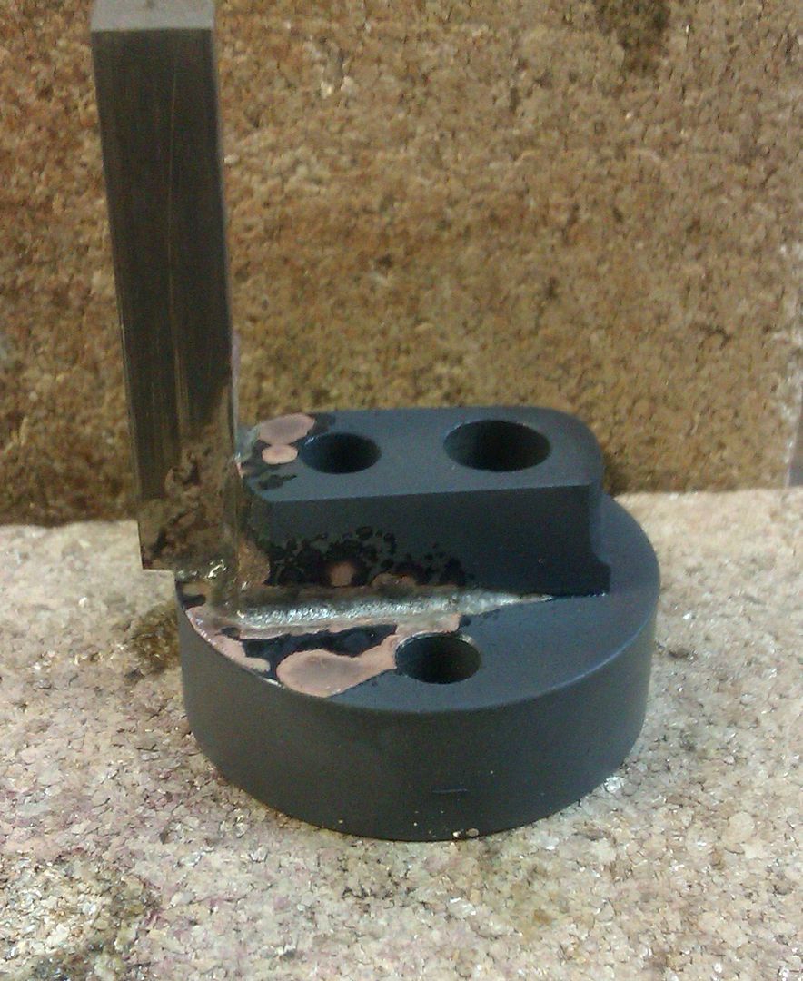
How I made sure it was square to the table.
IMG_4569 by Mark Savoca, on Flickr

Before some sanding.

IMG_4570 by Mark Savoca, on Flickr

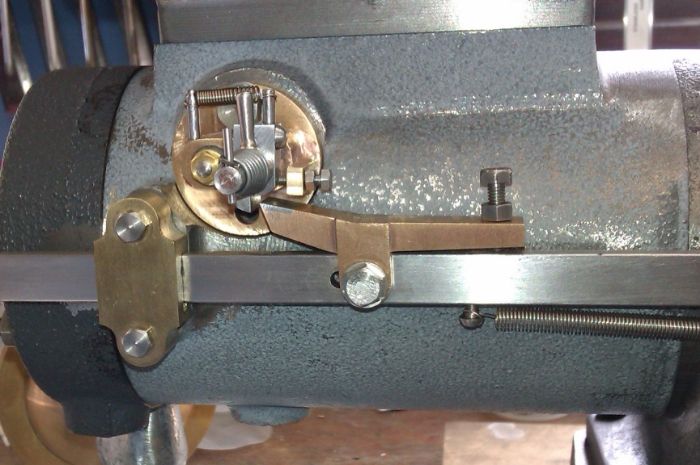
Finished sanding. Noticed the slot cut in the side. I guess I missed that picture...

IMG_4608 by Mark Savoca, on Flickr
 
Interesting, my first IC engine was a Little Brother and I am now working on a 1/4 scale Galloway. I am not as far along as you on the Galloway and It will take me a lot longer to complete than yours will I am sure (took me 36 years to complete the Little Brother!)
I have now seen 3 variations on bonding the cylinder sleeve to the cylinder. One was high temp RTV, one was JB Weld and now locktight. I guess I will cross that bridge eventually.
I saw in one of your pictures you have an end mill mounted in a drill chuck. Be very careful doing that, drill chucks are not meant for side loads.
Nice job so far and I will be following.

John
 
Thanks John. Some things can't be rushed :)

I couldn't reach with a collet so I used the chuck to spot face to have a flat surface to drill into. I guess I need a longer bit.
 
I started by mounting the aluminum casted piston and making it as true as I could so I could machine the end that will hold it while I machine the rest.

IMG_4616 by Mark Savoca, on Flickr

IMG_4617 by Mark Savoca, on Flickr

Once turned around I could bring it to the correct diameter.

IMG_4626 by Mark Savoca, on Flickr

I used the cylinder to make sure it was close but not too tight, about 3 thousands under.

IMG_4627 by Mark Savoca, on Flickr

I used the parting bit to cut the ring groves. To make sure the bit is square to the chuck I use a 2x3 block.

IMG_4628 by Mark Savoca, on Flickr

Laid out the locations for the rings.

IMG_4630 by Mark Savoca, on Flickr

I cut the rings and the oil groves, using a narrower cutoff bit.

IMG_4633 by Mark Savoca, on Flickr

IMG_4636 by Mark Savoca, on Flickr

To the milling machine to clean up the inside and drill and tap

IMG_4641 by Mark Savoca, on Flickr

I wasn't sure how to make sure I drilled the pin perpendicular to the inner surfaces, so I used two screws and 2x3 block.

IMG_4646 by Mark Savoca, on Flickr

Once everything was done I cut off the end.

IMG_4654 by Mark Savoca, on Flickr

Completed Piston

IMG_4660 by Mark Savoca, on Flickr
 
The material was a little two thick so I started by machines the ends to the correct dimension. The middle is going to be turned down so I did not machine it.

IMG_4673 by Mark Savoca, on Flickr

To save a little bit on time on the lathe, I milled it to rough size.

IMG_4683 by Mark Savoca, on Flickr

Some time on the lathe...

IMG_4685 by Mark Savoca, on Flickr

IMG_4687 by Mark Savoca, on Flickr

IMG_4689 by Mark Savoca, on Flickr

Now onto the brass casting that connects to the crankshaft.

IMG_4699 by Mark Savoca, on Flickr

I first squared the sides.

IMG_4700 by Mark Savoca, on Flickr

IMG_4702 by Mark Savoca, on Flickr

Hacksaws suck...

IMG_4704 by Mark Savoca, on Flickr

IMG_4706 by Mark Savoca, on Flickr

Using the sides squared earlier, I used the parallels and milled to spec.

IMG_4710 by Mark Savoca, on Flickr

IMG_4712 by Mark Savoca, on Flickr

Once both halves were ready, I machined the notches.

IMG_4713 by Mark Savoca, on Flickr

IMG_4718 by Mark Savoca, on Flickr

Drilled the two holes that will mount them to the piston rod.

IMG_4720 by Mark Savoca, on Flickr

To the lathe to machine the sides, step drill and ream for the crankshaft.

IMG_4723 by Mark Savoca, on Flickr

IMG_4728 by Mark Savoca, on Flickr

Time to drill the hole for the piston side.

IMG_4749 by Mark Savoca, on Flickr

IMG_4751 by Mark Savoca, on Flickr

And to turn the bronze bearing that will attach it to the piston pin.

IMG_4758 by Mark Savoca, on Flickr

Step drilled and reamed for the wrist pin

IMG_4761 by Mark Savoca, on Flickr

IMG_4764 by Mark Savoca, on Flickr

And then pressed in the piston rod

IMG_4766 by Mark Savoca, on Flickr

The wrist pin is pretty straight forward. Cut to length. Chamfered and spots milled.

IMG_4775 by Mark Savoca, on Flickr

All the parts

IMG_4777 by Mark Savoca, on Flickr

Making the square head screws. Using the tailstock to hold the die square.

IMG_4782 by Mark Savoca, on Flickr

IMG_4787 by Mark Savoca, on Flickr

I used two nuts and a large washer to mount the screw in the mill vise.

IMG_4788 by Mark Savoca, on Flickr

IMG_4790 by Mark Savoca, on Flickr

IMG_4792 by Mark Savoca, on Flickr

IMG_4793 by Mark Savoca, on Flickr

Mounted in place

IMG_4796 by Mark Savoca, on Flickr
 
Before I mount the brackets for the pushrod I wanted to complete the rocker arm. I can then use it to make sure everything is aligned.

Again the material was first machined to the correct dimensions, and laid out.

IMG_4803 by Mark Savoca, on Flickr

Holes drilled

IMG_4806 by Mark Savoca, on Flickr

I milled to rough shape

IMG_4811 by Mark Savoca, on Flickr

After a little sanding

IMG_4816 by Mark Savoca, on Flickr

And with the disk that will be silver soldered on

IMG_4820 by Mark Savoca, on Flickr

After soldering

IMG_4824 by Mark Savoca, on Flickr
 
Mark: Looking good!
Are you going to make the igniter or use a spark plug? If you are going to use the igniter there is a part missing from the plans, at least the plans I got about a year ago.

John

IGNITER-MISSING PART.jpg
 
John, I'm going to make the ignitor. Thanks for the heads up on the missing part. Looking quickly at my drawings it looks like it is missing on them.

Thanks,
Mark
 
It was missing on my 1/3rd scale drawings too, I opted to solder on a bit of brass and then machine it down to size which is more like the original which had the stop as part of the casting.

IMAG1924_zps9e73a696.jpg


IMAG1991_zps6b6ce5ef.jpg
 
Jason, I like that solution. I haven't got that far and at my building pace it might take a while!
I needed to 3D model it to understand how the darned thing works, wasn't clear to me from the prints.

John
 
Here's a short history of the ignitor drawings. When Ministeam acquired the castings, drawings and old stock for the Galloway series of engines they asked me if I would build one each of the engines, 1/3, 1/4, 1/6 and 1/8th as the originator of the engines didn't want to sell his finished engines. Having never constructed an ignitor before I reached out to the engine community for some guidance. I was given a tip from a forum member to add the little stop post to the ignitor base. When I updated the drawings sets I included the little stop post to the ignitor except for the 1/4 scale drawings which were done by someone else.
I'll first explain how the ignitor works and then the stop post will be better understood.
You have a base into which the parts are assembled. There is an insulated fixed post that the hot wire is hooked to. It projects out of the inside of the base and on the larger versions has a disc soldered to it to act as a point.
Now the trip mechanism: You have a shaft that projects out of both side of the base. On the inside you have a lever with a point which makes contact with the other point on the fixed post or touches the fixed shaft.
On the outside you have two pieces, a trip lever and a stop lever. The stop lever is clamped to the shaft and has a return spring which keeps the inside point arm from touching the fixed (hot) shaft.
Now you have a trip lever which slides onto the end of this shaft. It is connected to the stop lever by the conical spring that you see. When the exhaust valve pushrod with the trip arm engages the trip lever on the ignitor it starts to rotate it and in rotating it the spring connection then starts to rotate the shaft with the point arm. When the shaft is turned far enough the points make contact and allows the current to flow. At this point the trip arm disengages from the tip lever on the ignitor and the return spring pulls the point arm back to the open position. (No connection so no current flow.) When the points pop open a spark from the coil jumps across the points and ignites the air/fuel mixture.
Now the little stop post with the adjusting screw. On the smaller engines with the smaller ignitors there's not much room inside the spark pocket on the side of the cylinder. As the points are normally open, the return spring has the rotating shaft pulled back, due to the small space the moveable point arm can touch the inside of the spark pocket thereby allowing current to flow so with the adjusting post and screw you can set the amount of return travel on the rotating shaft so that it doesn't contact the the inside of the spark pocket.
Spark timing is achieved when the points open and the spark jumps from the insulated post to the moveable point arm.
It sounds complicated but once you see it work it makes sense.
 
George: Thank you for the explanation. After I modeled it I was able to noodle out how it works, or at least how I thought it should work, and your explanation confirmed what I thought.
Mark: If it's any help and you can read a 3D file I can send it to you when you are ready. Looking forward to more of your build.

John
 
I used the three jaw chuck to hold the flywheel for the initial turning. I used the dial indicator to get it as close to true as I could. I then turned the other side so I would have something better to hold on to .

IMG_4879 by Mark Savoca, on Flickr

IMG_4880 by Mark Savoca, on Flickr

This is the largest I can fit on my lathe. Everything was at the limit.

IMG_4882 by Mark Savoca, on Flickr

IMG_4883 by Mark Savoca, on Flickr

IMG_4861 by Mark Savoca, on Flickr

The surface for the governor weight

IMG_4854 by Mark Savoca, on Flickr

Step drilled

IMG_4862 by Mark Savoca, on Flickr

IMG_4864 by Mark Savoca, on Flickr

Repeat for the second Flywheel

IMG_4886 by Mark Savoca, on Flickr
 
The collars were made from 1" steel. Turned and bored to specification.

IMG_4917 by Mark Savoca, on Flickr

IMG_4921 by Mark Savoca, on Flickr

IMG_4923 by Mark Savoca, on Flickr

IMG_4925 by Mark Savoca, on Flickr

Up next is the Arm. It is made from 3 parts, the fork, arm and pad. First I laid out the the fork.

IMG_5014 by Mark Savoca, on Flickr

I first drilled to get the inner diameter. I then milled the two sides to make a U.

IMG_5017 by Mark Savoca, on Flickr

I then milled to correct height. You will also see that I used the belt sander to round the outside. I have a rotary table, but have not had good success using it yet.

IMG_5019 by Mark Savoca, on Flickr

With the collar sitting in it.

IMG_5022 by Mark Savoca, on Flickr

Cut off from the stock and milled a groove for the arm to fit into.

IMG_5026 by Mark Savoca, on Flickr

Next I machined the material for the arm to the correct thickness.

IMG_5028 by Mark Savoca, on Flickr

I then laid out the arm. I left each end longer then required so I could adjust if needed.

IMG_5030 by Mark Savoca, on Flickr

Drilled for the slot.

IMG_5032 by Mark Savoca, on Flickr

Cutting it down to rough size and shape.

IMG_5044 by Mark Savoca, on Flickr

IMG_5046 by Mark Savoca, on Flickr

Sitting in place

IMG_5049 by Mark Savoca, on Flickr

The parts. You can see the slot milled for the pad.

IMG_5050 by Mark Savoca, on Flickr

Next I drilled the fork for the two screws that will eventually mount it to the collar.

IMG_5076 by Mark Savoca, on Flickr

To drill and tap the collar, I used the wiggler to find each side and therefor the center. Center drilled and tapped.

IMG_5078 by Mark Savoca, on Flickr

With one side mounted, I used a transfer punch to gently mark the second hole.

IMG_5079 by Mark Savoca, on Flickr

To help me make sure it is aligned, I left a bolt in the other side and tried to hold it flush as I put it in the vise.

IMG_5082 by Mark Savoca, on Flickr

Another picture with it sitting in place.

IMG_5085 by Mark Savoca, on Flickr

Outside to silver solder. You can see I also used the belt sander to round off the ends.

IMG_5091 by Mark Savoca, on Flickr

Soldered sitting in place. The screws are just temporary.

IMG_5092 by Mark Savoca, on Flickr

Cleaned up with a wire brush in the drill press.

IMG_5098 by Mark Savoca, on Flickr

IMG_5100 by Mark Savoca, on Flickr

The completed arm and collars.

IMG_5102 by Mark Savoca, on Flickr
 
Very nice work on the governor lever! This is one of those small parts that's a real pain to make.
gbritnell
 
Laid it out and drilled to form the basic curves

IMG_5131 by Mark Savoca, on Flickr

IMG_5134 by Mark Savoca, on Flickr

Then I removed much of the extra material

IMG_5139 by Mark Savoca, on Flickr

IMG_5143 by Mark Savoca, on Flickr

IMG_5148 by Mark Savoca, on Flickr

Cleaned up some and used belt sander to round out some

IMG_5177 by Mark Savoca, on Flickr

With the Catch finger

IMG_5188 by Mark Savoca, on Flickr

Sitting in place

IMG_5197 by Mark Savoca, on Flickr

I left the latch end long until I complete the pushrod side.
 
Started with a small .250 x .250 blank

IMG_5218 by Mark Savoca, on Flickr

Used the four jaw and dial indicator to center the square.

IMG_5220 by Mark Savoca, on Flickr

Because the 4 jaw chuck won't hold such a small item, I used some scrap to give me some more room.

IMG_5221 by Mark Savoca, on Flickr

Turned down to fit into the hole drilled into the pushrod

IMG_5222 by Mark Savoca, on Flickr

I machined the catch square initially,

IMG_5225 by Mark Savoca, on Flickr

I then used a file to give it more of a lip to catch on.

IMG_5227 by Mark Savoca, on Flickr

Attached to the pushrod with red Loctite.

IMG_5228 by Mark Savoca, on Flickr

The Catch Plate screw was pretty straight forward, but fun.

IMG_5247 by Mark Savoca, on Flickr

IMG_5248 by Mark Savoca, on Flickr

IMG_5249 by Mark Savoca, on Flickr
 
I had not drilled the main bearing caps for the grease cups and the anti-rotation pin. So I did.

IMG_5211 by Mark Savoca, on Flickr

IMG_5212 by Mark Savoca, on Flickr

Mounted back on the mill to drill for the anti-rotation pin.

IMG_5214 by Mark Savoca, on Flickr

Made some very small pins.

IMG_5215 by Mark Savoca, on Flickr


With the pushrod in place I noticed the it hit the base when the pushrod was pushed open.

IMG_5253 by Mark Savoca, on Flickr

So back onto the mill to be cleaned up a little.

IMG_5251 by Mark Savoca, on Flickr

All together. I trimmed the catch, but still left it long.

IMG_5256 by Mark Savoca, on Flickr

IMG_5265 by Mark Savoca, on Flickr
 
Back
Top