


Several years ago, I did a series on cutting spur gears using the methods in the “Workshop Practice Series” book #17, “Gears and Gear Cutting” by Ivan Law:
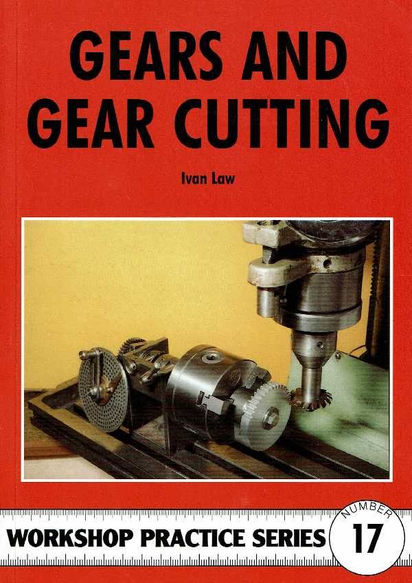
Mr Law's method works great. You can follow his techniques without deviation. However, recently I found another method to cut gears that approximates involute tooth using only one cutter to form gears of any size within the diametral pitch. The method is described by "Helicron" at his website.
http://www.helicron.net/workshop/gearcutting/
I followed Helicron's technique with good results.
First step is to make the cutter tool. My lathe is not rigid enough to make the cutter as Helicron shows. Instead mine is a single point cutter with most of the blank removed before forming the cutting teeth.
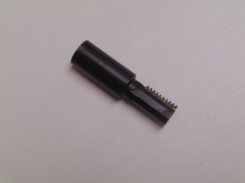
The steel for the cutter is alloy “O1”. O1 is the most widely used tool steel and is available from McMaster Carr and other suppliers. O1 is very easy to work with and harden. Shape and form the tool to the desired size. Heat with a torch to 1400 degrees F, which is cherry red heat in room light. Plunge in oil to quench. I used some leftover salad oil from the kitchen. Leave in the oil quench about 30 seconds, it cools down slowly. Quenched tool steel is too brittle at this point and needs tempering. To temper, suspend the tool in a small pot of salad oil on the kitchen stove. Heat to 350 degrees F using a candy thermometer to check the temperature. Leave it in about 10 minutes, pull out and let air dry. The O1 steel comes out very hard and will cut just about anything.
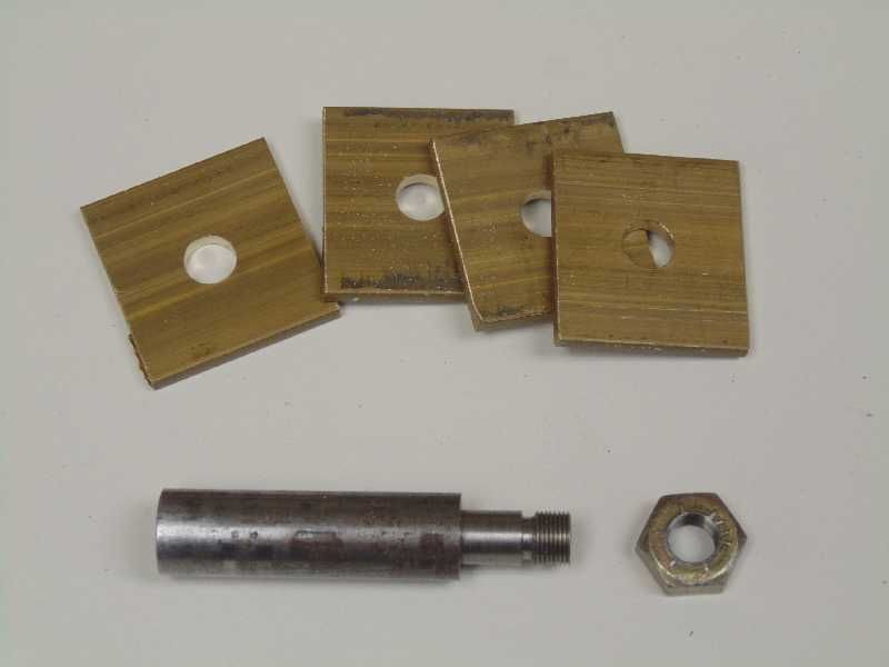
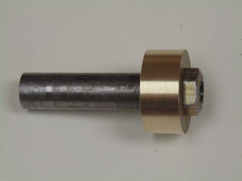
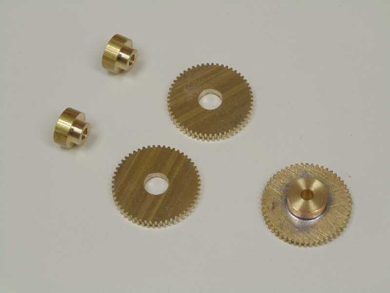
For an upcoming project I want to cut some 48 diametral pitch gears with 52, and 16 teeth. First, the 52-tooth gear. These are from 1/8” thick flat brass bar. First, make a shank from length of 1/2" diameter steel in the lathe cut and turn a 5/16” diameter boss. Thread the end to accept a nut. Gang up four pieces of brass stock on the shank.
Turn the ganged stock to the final diameter for the gear. In this case 1.125"
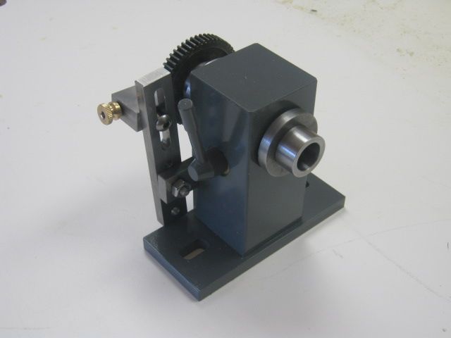
To cut the gears I used my little, homemade Harold Hall dividing head. It is a “direct indexing” head that uses the change gears from the Atlas 6” lathe for indexing. The spindle hole is tapered with #2 Morse Taper (2MT). A 2MT collet holds cinches stock tightly in the dividing head be means of a draw bar.
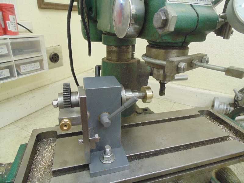
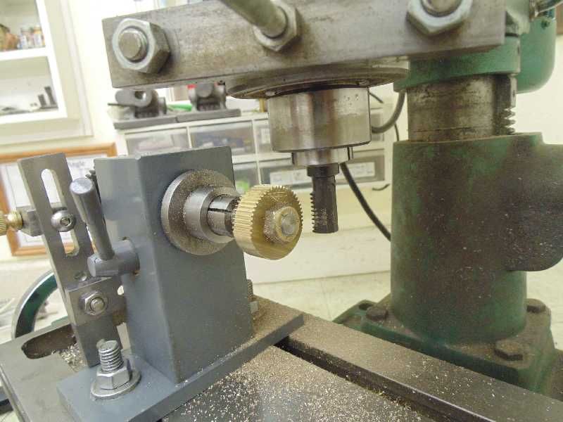
Secure the 52-tooth lathe change gear to the spindle of the dividing head. Mount the dividing head to the mill table. Use a 1/2" 2MT collet to chuck the gear blanks. Chuck the gear cutter in the mill spindle and use a height measure device to set the gear cutter height.
Adjust the depth of cut and start cutting. depth of cut on 48DP gears is 0.045". Advance the dividing head spindle one notch on the indexing gear.
Finish the 52 tooth gears by soft soldering an appropriate hub. Drill and tap for a set screw.
Next time we will cut the 16 tooth gear and do something with the results.

Mr Law's method works great. You can follow his techniques without deviation. However, recently I found another method to cut gears that approximates involute tooth using only one cutter to form gears of any size within the diametral pitch. The method is described by "Helicron" at his website.
http://www.helicron.net/workshop/gearcutting/
I followed Helicron's technique with good results.
First step is to make the cutter tool. My lathe is not rigid enough to make the cutter as Helicron shows. Instead mine is a single point cutter with most of the blank removed before forming the cutting teeth.

The steel for the cutter is alloy “O1”. O1 is the most widely used tool steel and is available from McMaster Carr and other suppliers. O1 is very easy to work with and harden. Shape and form the tool to the desired size. Heat with a torch to 1400 degrees F, which is cherry red heat in room light. Plunge in oil to quench. I used some leftover salad oil from the kitchen. Leave in the oil quench about 30 seconds, it cools down slowly. Quenched tool steel is too brittle at this point and needs tempering. To temper, suspend the tool in a small pot of salad oil on the kitchen stove. Heat to 350 degrees F using a candy thermometer to check the temperature. Leave it in about 10 minutes, pull out and let air dry. The O1 steel comes out very hard and will cut just about anything.
For an upcoming project I want to cut some 48 diametral pitch gears with 52, and 16 teeth. First, the 52-tooth gear. These are from 1/8” thick flat brass bar. First, make a shank from length of 1/2" diameter steel in the lathe cut and turn a 5/16” diameter boss. Thread the end to accept a nut. Gang up four pieces of brass stock on the shank.
Turn the ganged stock to the final diameter for the gear. In this case 1.125"
To cut the gears I used my little, homemade Harold Hall dividing head. It is a “direct indexing” head that uses the change gears from the Atlas 6” lathe for indexing. The spindle hole is tapered with #2 Morse Taper (2MT). A 2MT collet holds cinches stock tightly in the dividing head be means of a draw bar.

Secure the 52-tooth lathe change gear to the spindle of the dividing head. Mount the dividing head to the mill table. Use a 1/2" 2MT collet to chuck the gear blanks. Chuck the gear cutter in the mill spindle and use a height measure device to set the gear cutter height.

Adjust the depth of cut and start cutting. depth of cut on 48DP gears is 0.045". Advance the dividing head spindle one notch on the indexing gear.

Finish the 52 tooth gears by soft soldering an appropriate hub. Drill and tap for a set screw.

Next time we will cut the 16 tooth gear and do something with the results.
Last edited:


