Quarter Scale Merlin V-12

Home Model Engine Machinist Forum

Help Support Home Model Engine Machinist Forum:

This site may earn a commission from merchant affiliate links, including eBay, Amazon, and others.
The distortion comes from within the metal itself as you've discovered.
This is due to internal stresses and atom alignment.

Simplified it's like layin bricks, there's a certain logic in which metals are formed or bricks are layed. When removing some metal or by inducing stress (turning/bending etc.) the layout is changed and this can cause some metals to "move" to another position.

2-0.jpg

van-houtte-fig-11-1024x618.jpg


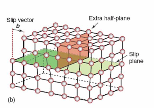
In the first pic there arent any atoms removed but rather "chushed" together like you would in a bending/rolling/pressing situation.
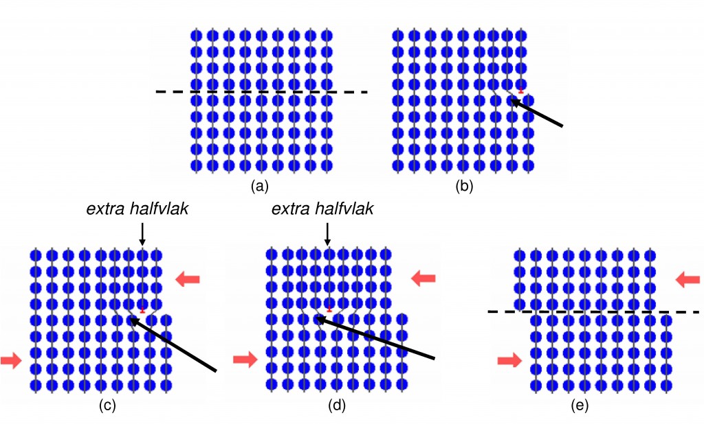
During the removing process of surrounding metal (turning/milling/cutting) at a certain point situation C can become D which doesnt change the form.
But the build up tension is released in situation E the product becomes distorted (elleptical in your example)

The heat treatment removes build up stress in the part which can cause shifts in the pattern and settle's the metal in its new form. Finish turning induces much less stress which helps to keep the form. It "regenerates" the structure to form E so there's no left over stresses (or a lot less depending on the time and temperature in the oven).


The way some bar stock is made by pressing/rolling induces stress in a certain form. Making square bar stock unsuited for this kind of application.
 
The prior post somewhat supports my supposition that the outer portion stress relieves easier than the inner as it is more "flexible".

If you were to make rings from the "bad" portion, they might relieve back to round after being parted. Or did you already try that?
 
Maybe.....
But, for my radials' one inch rings, I supported the ring blanks in two different 5C collets and had pretty much the same experience. - Terry
Sounds like there are other factors beyond the chucking issue but (for what it's worth) the ER system has 8 clamping elements instead of the 3 with 5C.

Could the OD blank be turned & finish honed between centers? (Sunnen hone) Come to think of it maybe a fixture to clamp a stack of compressed semi-finished rings then their OD's finish honed to final size??
 
The prior post somewhat supports my supposition that the outer portion stress relieves easier than the inner as it is more "flexible".

If you were to make rings from the "bad" portion, they might relieve back to round after being parted. Or did you already try that?

Initially, it sounds counterintuitive, but no, I've never tried that. I normally discard at least the outer eighth to quarter inch. I'm no expert, but it seems to me that since cast iron is cast and not rolled, the internal stresses that Napoleonb is referring to might be found all through the material but especially on the outside depending upon how it cooled. I would guess the outer layers would cool first and lock in the volume available for the inner layers. But, as the inner layers cool, the material shrinks and maybe become less stressed. Perhaps one of the reasons for the centrifugal casting/cooling is to equalize some of this.
In any event, I find cast iron frustrating and messy to work with, and I try to avoid using it except for one of the most critical components in every engine I build :>) Terry
 
Last edited:
Continous cast iron bar is readily available in the UK dunno about the States but it is very uniform in construction and grain size.
 
After a two hour soak at 975F, the first batch of rings were allowed to cool overnight before opening their sealed packaging. There were a few black soot deposits on the fixture, but the rings were relatively clean. Before removing the rings I burnished their collective outside diameters using a white Scotchbrite pad. The pad doesn't remove any metal, but it does remove most of the fine deposits that inevitably collect on the outer surfaces of the rings during heat treatment. These deposits are barely visible, but they leave a slightly rough surface on the rings' polished o.d.'s. More importantly, they create problems for the light test because they cause the rings to stand off from the cylinder wall. Light leaking from around an entire ring makes it appear too small in diameter for the cylinder. If left alone, these abrasive deposits will just rub off the rings and wash into the engine oil during the first few seconds of running. If a light test is to be performed, however, they need to be removed because they can hide fitting errors.

In my experience, it's typical for a few rings to become stuck together during the heat treatment. The deposits that form on the rings' outer surfaces sometimes tend to lightly bond them together at their outside corner edges. They're easily separated with a razor blade by carefully prying them apart at the inside edges of their gaps. Before I started using argon gas as an air displacer, I tried including bits of various sulphur-free papers inside the sealed package as some have suggested. The theory is that the paper will burn up, and the bit of smoke that is released will generate a reducing rather than an oxidizing atmosphere inside the envelope. Every time I've tried this, I've ended up with a gooey coating on the rings that was difficult to remove and a lot of stuck-together rings. After several tries, I switched to using argon from one of my welding gas cylinders. I've read that the rings can also be coated with a borax fluxing agent to protect them. If there's a next time, I may also try that.

While the rings from the second blank were going through their heat soak, I began finishing and testing the first batch of rings. A running gap of .004" was filed into the ends each ring using a thin diamond file. A diamond file is cleaner because it doesn't magnetize the cast iron while it's being filed. The minimum gap was verified using a feeler gage with the ring installed inside the top end of a cylinder liner. The sides of the rings were then lightly lapped on a glass plate using 1000 grit grinding grease. The fixture used for this step supported the rings by their o.d.'s unlike the i.d. fixture used for lapping the rings before they were gapped. The rings' o.d.'s were once more burnished with a white Scotchbrite pad to remove any deposits missed earlier. This was done using a simple two-part fixture made to safely grip the rings one at a time so their shapes were not stressed during the burnishing. Special care was required around the gap to prevent the pad from grabbing one of the ring's ends and deforming it.

For the light test adapter, I turned a black Delrin plug with an o.d. that was about .020" smaller than the i.d. of the cylinder. A shoulder was also turned on the plug so the ring-under-test could slip on to it. With the ring installed on the bottom of the plug and the combination sitting square in the top end of a cylinder, a high intensity flashlight was shined into the bottom end of the cylinder. Any light leaking between the ring and the cylinder wall is easily visible from above the cylinder. My criteria for a good ring was that there be no visible light except for that passing through the ring's gap. I've included a few photos of some of the test results.

The magnitude of the errors can be roughly estimated by comparing the widths of the light leaks to the light passing through the .004" gap. Most of the errors I saw were much greater than the circularity errors in the blank material. These errors evidently resulted from the material further relaxing after parting/gapping or from handling issues during the final finishing steps. I'd like to believe that most of the rejects resulted from the former and not the latter since installing the rings on the pistons always feels like the most traumatic step in their handling.

When completed, 34 of the 49 rings parted from the two blanks passed my light test. This 70% yield was a bit lower than expected, and it reduced the net yield of the finished portions of the blanks to about 30%. Even with the poor yields I ended up with ten spare rings.

Finally, I selected one of the good rings and used it to verify the i.d.'s of all the cylinder liners machined earlier. Of the fifteen liners, eleven had no light leakage. Three of the remaining four had just a hint of a leak, but one was large enough to be scrapped. - Terry

1133.jpg


1134.jpg


1135.jpg


1136.jpg


1137.jpg


1138.jpg


1139.jpg


1140.jpg


1141.jpg


1142.jpg
 
On another issue ...

One of the stents that was put in my heart last April has developed a problem, and I'm soon going into the hospital for open heart surgery that's now required to fix it. While I'm in there, the doctors also plan to repair my aorta which evidently also needs attention. I've been told to expect a long recovery time, but recovery sounds like a good thing. Although the Merlin has recently been a nice diversion from the personal loose ends I'm now scrambling to tie up, there won't be any more posts for a while. I wish everyone a safe and happy holiday. - Terry
 
Last edited:
Here's to a quick and speedy recovery Terry. All the best and look forwards to your return with good health.

Andrew
 
Terry, All the best for your recovery, All the best to you and the family for the holidays, Hope to see more when you are up to it.

Cheers
Andrew
 
If your surgeon is as skilled as you in his trade you should be fine.

Good luck & a speedy recovery.

Regards,
Ken
 
Praying for a successful out come and a quick recovery.

Ron
 
Terry,
All the best for your recovery. Health is more important than everything else.
gbritnell
 
Back
Top