90 degree joint in rotating shafts

Home Model Engine Machinist Forum

Help Support Home Model Engine Machinist Forum:

This site may earn a commission from merchant affiliate links, including eBay, Amazon, and others.
I must agree it's a fascinating motion. We could have a competition amongst the members to find the best practical use for this device. :cool:
 
With the reciprocating motion, you should have a basin at the bottom and a piston pump to lube the sliding portion.
 
Someone on another forum suggested that if the orange plate was made symmetrical about center and had a third lobe added, then there could be two output shafts driven in opposite directions if the blue shaft was the driver.
 
(Tongue in Cheek)

Perhaps as part of another marble machine. I am always mesmerized when you build devices to put your engines to work.

I like the idea of two outputs with two things happening, perhaps mirroring each others' actions.

Whoa! Sorry. I just turned an easy week's work into something more ambitious. Didn't mean to do that. (Unintended Consequences.)

--ShopShoe
 
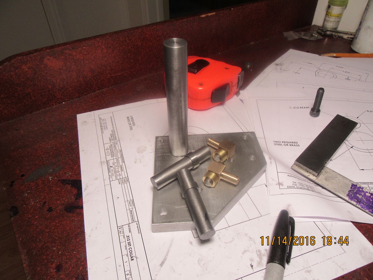
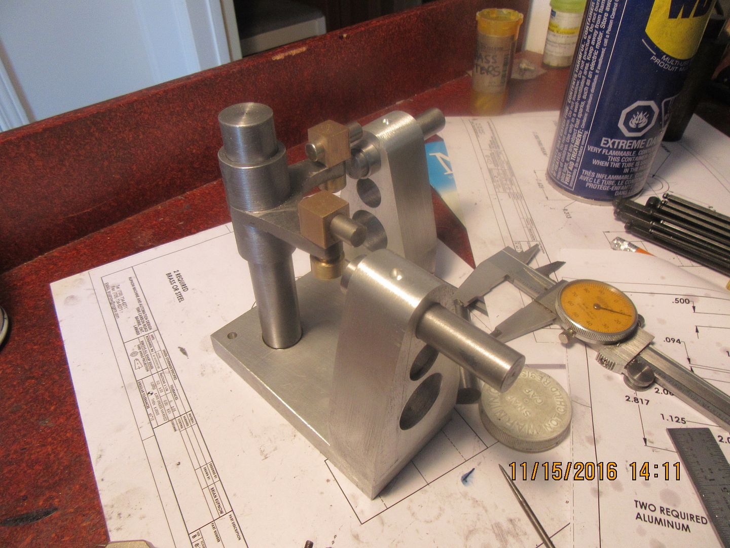
I spent most of the day working in a factory across town that uses me for engineering work they need done. Then I came home and played. I have a most wonderful collection of "bits and bobs" that all have a home on the wonky joint. I had a change of heart at the last minute and made the base from 1/2" aluminum plate and the vertical 3/4" upright is made from 1045 steel with a 5/16"-18 thread in the bottom. Initially I was going to go with a steel base and weld the upright to it, but decided I had a better chance of everything staying "true and square" if I bolted the 3/4" diameter upright in place with a 5/16" socket head capscrew. The square bits with the round extension on them are made from some grade of bronze. I'm still using up scraps from that big bronze weight that I reclaimed from the dump. I might finish this thing tomorrow.
 
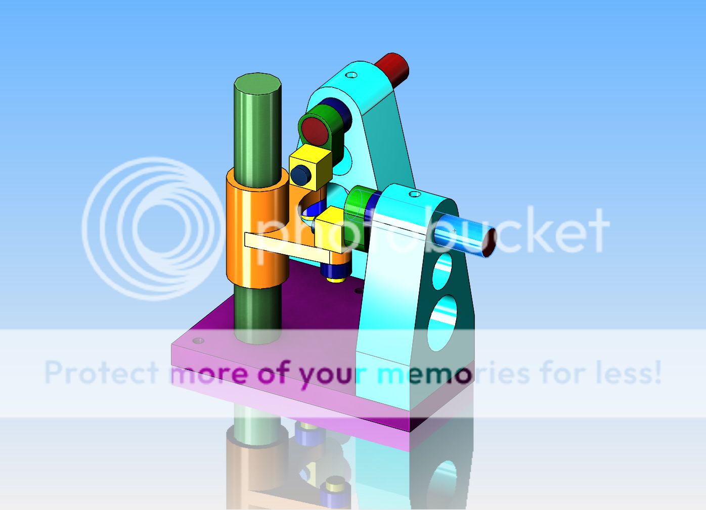
There is far more that I don't know about this mechanism than there are things that I do know. It is a straight 1:1 ratio. Yes, with minimal tweaking there could be two output shafts. I first seen it on a "mechanisms" website, then modelled it in 3D cad and animated it. It appears that it will work, but I will hold my final opinion of this until I see this one running. In all of my 70 years I have never seen a mechanism like this on anything, which leads me to believe that either it doesn't work all that well, or else is too expensive to make compared to miter gears. I am building it more for the "Neat eye candy effect", not as an potential replacement for gears. If it does work well, I'm going to do something a bit different, and drive it with one of my steam engines. I have been so rapped up in i.c. engines for the last few years that my collection of various steam engines have only been holding down shelves in my office. And yes, when I have it working properly, I will post a link to a download of the drawings, for anyone daring enough to build one for themselves.
 
Brian, I see no reason why this thing should not work very nicely. There are two points I would watch. The Orange Sliding Thingy needs to slide smoothly and easily on the post, with plenty of bearing length (perhaps relieved in the middle to provide an oil reservoir). There will be lateral and axial forces where the Yellow Knuckle Doofers pivot in the Thingy so I think they could perhaps do with more bearing length and/or broader thrust faces. Oh and thirdly, it will be important to ensure the crank throws are accurately equal. Also, though I am sure you are aware of this one too, don't forget sufficient crankpin length to allow for the 'big ends' to slide axially.
 
There is a commercial version of this at the New England Museum of Wireless and Steam. It was made to go in line shaft operation to turn the shaft around a corner. It As I remember its for about 2" shafts. So these were made and used many years ago.
 
There is a commercial version of this at the New England Museum of Wireless and Steam. It was made to go in line shaft operation to turn the shaft around a corner. It As I remember its for about 2" shafts. So these were made and used many years ago.

Here is my version done a few years back of the Museum's version...Almond Mfg company made the original versions.

https://youtu.be/Am9i0GV8ty0
 
I'm almost there. I have two pieces left to make, and have to scare up a pulley. So far I'm happy with what I am seeing, but I need those last two pieces before I can declare a success or a failure.
 
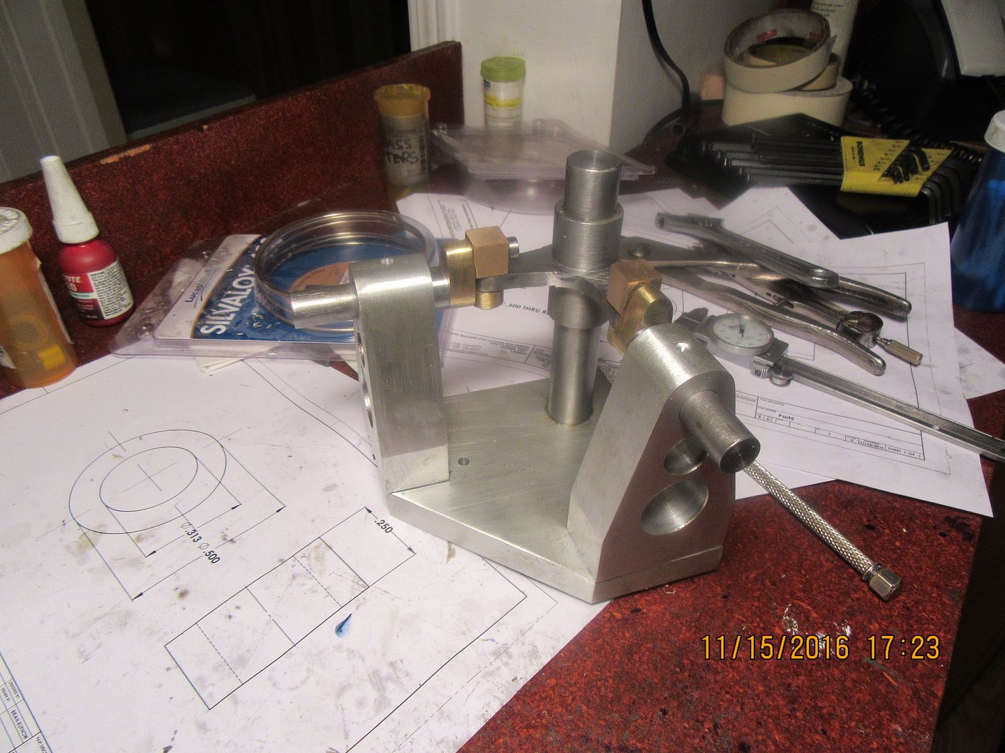
So, there we have it, except for a drive pulley. Does it work?--Well, sort of. I grabbed one shaft with my (shudder) vice grips, and turned it. It is very stiff, but is looked as if it wanted to work. The little square bronze parts that have a 5/16" round "extension" on the bottom that passes thru the 1/4" steel plate need to have a retainer on them, or at one position in the sequence they pull straight up out of the plate. I knew it would try and do that, so I had pre-made a pair of bronze "retaining collars" to slip over the ends and trap the plate. I didn't make anything mechanical to do this, just a bit of 620 Loctite retaining compound. I want to give the Loctite a few hours to set up, and during that time I will make a pulley to go on the input shaft.
 
YES!!!! IT WORKS!!! I have to put a motor on it and drive it for a while to get any tight spots out of it, but I did find a big V pulley to fit and have been turning it by hand. Video tomorrow.
 
Good wife and I just returned from the Princess Alexandra theater in Toronto. Seen a musical called 'Come from away', about the 7000 people who's planes were diverted to Gander air base in Newfoundland, Canada, during the 9/11 crisis. Sounds like a strange premise for a live play, particularly a musical. However, it was good. It was really, really good!! Made me laugh, made me cry, touched all the buttons that a good live musical will do. That was my dash of culture for this year.---Now---As for the strange 90 degree shaft joint-----when I first assembled everything, I coated all of the sliding and rotating members with grease. This worked, and did the job for the initial running, as you seen in the video. The longer it ran, though, the harder the drill had to work. It was stiffening up, not loosening up. My next amazing stunt was to reach for the can of spray on WD40 that I use when cutting aluminum in the mill or lathe. I gave everything that moved a liberal shot of WD40, which immediately washed out the grease and made the joint even stiffer. At this point I was wondering what I should do next, so I grabbed my squirt can of #40 automotive lubricating oil and gave everything a good squirt. This immediately fixed things and loosened everything up again.--My forensics on this, are that although the grease provided initial lubrication, it very soon loaded up with microscopic metal particles, as all of the rotating and sliding parts "wore in". All of the metallic particles were then held in suspension in the grease, and instead of a lubricant, the grease itself became a fluid abrasive and was jamming instead of lubricating. the WD 40 then washed out any of the remaining grease, and left basically a metal on metal situation. Then the #40 lubricating oil washed out the remaining metal particles and saved the day. I have sussed this out based on the greasy, gritty residue that has dripped onto the aluminum baseplate from the rotating joints.
 
Back
Top