Bazmaks version of Niels diamond tool holder

Home Model Engine Machinist Forum

Help Support Home Model Engine Machinist Forum:

This site may earn a commission from merchant affiliate links, including eBay, Amazon, and others.
Joined
Dec 12, 2012
Messages
2,220
Reaction score
1,285
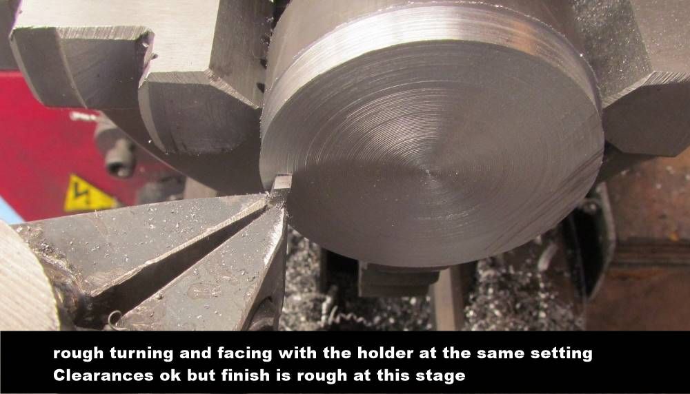
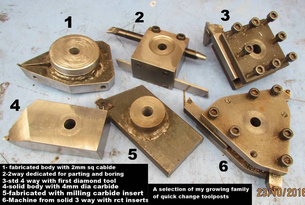
Niels kindly supplied me with a piece of 2mm sq and 4mm dia carbide
I machined from solid a holder for the 4mm dia carbide and was impressed
so I decided to make a holder for the 2mm sq.Did thing differently to avoid
having to cut/broach the 2mm sq hole and also hacksaw a slot for clamping
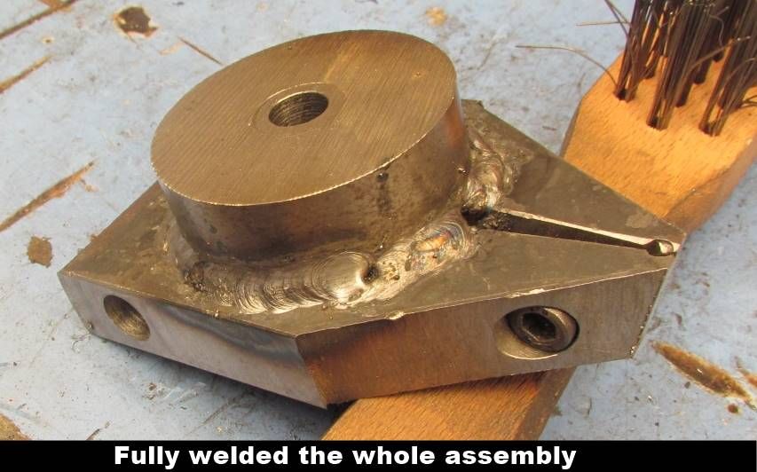
I fabricated from 3 pieces of steel and finished the clamp/holding slot
before fully welding together.A little bit more involved but easier and works
well.Following photos show how I went about it
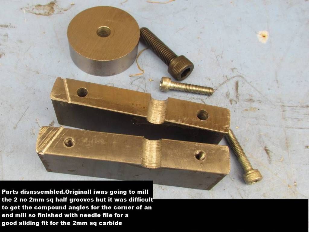
One suggestion for NIELS is to use a larger section of sq carbide
2mm is good for fine detail/light cuts but its size makes it difficult
to get the clearances to front and side
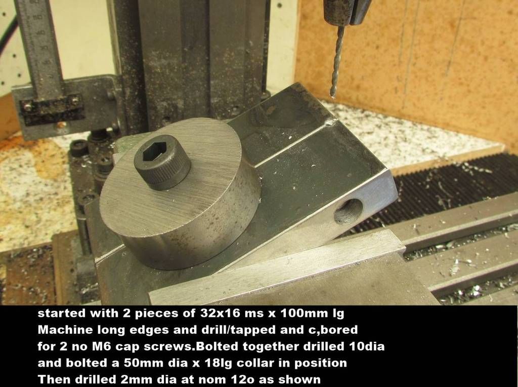
 
Hello Barry and thank You for trying new ways and documenting them with pictures.
May I propose that the upper surface of the clamping parts are made flush with lathe centerline?
Very easy to turn on lathe face plate and makes readjustment after re-grinding/sharpening very fast.
I do not remember if the piece of 2mm almost square carbide I have sent has its cutting corner broken,rounded or is still german sharp,geometric correct or whatever I shall describe it?
If line-sharp ,let me send You another where corner has been chamfered .2 mm.
A little work with a diamond file and it is almost round with .2mm radius like standard inserts.
When You get a carbide able stone for regrinding ,please try to re-grind the 4 mm round (12.6 square mm) and the 2 times 2 almost (Less than 4 square mm) and tell us if a 4 mm almost square (16mm square) is still a sensible idea?
I will post a 3mm almost square( more or less 9 square mm) with chamfered edge/cutting corner tomorrow for Your next holder.
Have You tried to cut almost 2 mm wide swarf?
 
Hi Niels,many thanks for your advice.The height for the tool above the compound for my lathe is 18.25mm.The holder is 16mm with a light skim making it 15.5mm.Therefore the top of the carbide is 2.75mm above the holder
With it angled at nom 12/15o this helps produce the clearance.If the carbide
was level with the top of the holder the front cutting point would have no clearance with the holder.If you understand my rambling.On your previouse threads you mentioned the easily cutting 2mm deep,but I cannot see that with a 2mm sq carbide.With the holder set at 45o to the lathe axis and the top of the tool ground at 5o more than the carbide rake then there is just enough
side and front clearance to both turn and face without moving the holder.The holder can be swung more for facing or less for turning.
Only just finished the tool so have not tried it fully yet.As you say a small radius will help.However photo of my tool no 4 ,made from solid and fitted with the 4mm dia carbide,does easily cut 2/3mm deep with a great finish.My idea would be to use the 4mm dia for main turning and the 2mm sq for fine finishing sq corners or undercut.If you have 3 or 4mm carbide I would like to give it a try,with a donation to RSPCA. Regards barry
 
Hello Barry.

I have made a Myford almost square 3 mm holder and it is not really good.
Problem is that Myfords are 15.7 mm from compound to center and Your SC4 is 18.25.
It is to short for getting a satisfactory grip on a 3 mm carbide stick in a mild steel holder .
With a 2 mm holder my Myford friend gets happier and happier each time he uses it.
I post a picture of my own 2mm Boxford holder seen directly from above and then a close up of combat zone.
The 0.1 mm toolholder clearances from carbide stick cutting edge lines are made as the last operation before skimming bottom and top to be 25.14 mm separate.
If You make your clearence like that there is no problem facing and cutting with same toolposition.Please try that and maybe also the regrinding exercise 2 mm almost square versus 4 mm round to judge the extra nuissance.
If You still want to try 3 mm almost square I have two left for the time being.

baz1.jpg


baz2.jpg
 
Looks good on large scale sketch but what is the distance on the 2 outer corners of the holder,gripping the carbide.It looks to be less than 1mm.
I assume this increases as you go lower down the holder but even so
it appears to be insufficient to me and the carbide is outside of the holder
The carbide will be gripped very little like a pair of tweezers and tightening the clamping action will deform the tip very quickly.Just my thoughts,you have much more experience than me
 
Hello Barry

We are getting very close to the geometrical limits of tangential tools being either round, square or triangular.
First picture shows my 25.14 mm high toolholder of mild steel for 2mm almost square carbide.
Next is a imaginary cut through the pinch and last is a view of the pinch.
If You only have the myford 15.6 mm heigth available and want to use a 1/4 inch square bit it gets ridicolus small.
Solution can be to use a much stronger material for holder or buy the Eccentric thing.
That thing overhangs a lot but has space for much more pinch area below compound slide upper surface.
A 1/4 inch carbide is not nice to regrind by the way..

baz3.jpg


baz4.jpg


baz5.jpg
 
Hello Barry

We are getting very close to the geometrical limits of tangential tools being either round, square or triangular.

If You only have the myford 15.6 mm heigth available and want to use a 1/4 inch square bit it gets ridicolus small.

A 1/4 inch carbide is not nice to regrind by the way..

I've asked a similar sort of question before but was never answered.
What do you mean by the limits of tangential tools as Tom Walshaw writing as Tubal Cain published his designs which were -
1. for a Myford- he had two
2. he was using 'bigger than 1/4"'

True, he wasn't using carbide but so far, no one seems to have tackled the shaping of carbide tools. Honing then 'Yes' but not shaping them and merely doing the tops when the rest of shaping and finishing has been done- before the point of sale.

As I have said elsewhere, I have two Myfords but have not said that I was developing cutters in carbides for factory and indeed international production in the early 1950's.

True, I had all the company resources at my disposal- but I certainly haven't now.

I'd like a few concrete answers and I suspect that I will not be alone in this matter.

Regards

Norman
 
as Tom Walshaw writing as Tubal Cain published his designs which were -
1. for a Myford- he had two
2. he was using 'bigger than 1/4"'


Regards

Norman

Hello Norman

I do not know what You referring to
Can we see a picture and some words?.
 
I don't 'do' pictures for several reasons. One was that I ran into litigation about publishing from magazines and books which were 'becoming lost' and several of us thought it would be a contribution to those following on in the hobby.

As far as the legality of information on tangential tooling, I have mentioned that it and other topics are out of copyright and I really feel that that if no one can be minded to do a little searching themselves , it is a poor reflection on them. Repeating myself for the umpteenth time- the word Holzapffel is definitive.

More recently, Tubal Cain- Tom Walshaw wrote it all up in either Model Engineer or Model Engineers Workshop- subject to copyright threats made to me- and he then incorporated it in his 'Simple Workshop Devices'. What resulted in the initial publication was the classic argument about 'angles'.- by other model engineers. Again, I'm unable to enter the copyright business yet again.

So with these matters firmly in mind, I am asking for you to clarify the information pertinent to your tooling project.

Surely you must clarify what are the limitations. Again, I asked what your solutions were to 'carbide grinding' in your particular application.

Repeating myself, I'm sure that I am not alone in this.

My good wishes

Norman
 
A couple of pictures to show why some homemade tangentials can be unsuitable for smaller lathes.
First picture shows two on top made for a Boxford (25.14mm) and Myford(15.60mm) each holding a 3mm round carbide costing me less than 2€ when I buy many.
Next row is for almost square 2 mm carbide I modify myself and would have to ask for over 20€ if I did it for a living.
Then low rigth is a Boxford 3mm almost square version.
They are all able to go into a 90 degree corner with about .2mm clearance.
As it can be seen the 15.6 mm Myford versions have very little material to grip the carbide and a 3mm square does look absurd.My friend has one but prefers the 2mm almost square and 3mm round versions he also have.
Barry has a lathe with 18.25 mm.If I had known that,I would have sent him a 3mm round carbide instead of the 4mm he got.
A 3mm or even 4 almost square are not recomended with 18.25mm heigth available.
It will be my next journey to make a Myfordable for 2mm round carbide.


Link is for better resolution
http://imgur.com/a/iFtZb

WP_20161031_002[2].jpg


WP_20161031_005[1].jpg
 
Niels, pardon the stupidity in this question- but are the bits being fed into a round hole on the tool holder?
What keeps them in the right direction- just the tension from the screw alone?
 
Radar..there is no such thing as a stupid question...if you don't ask you will never know..cheers clem
 
Hello Radar
The round carbide sits in a round hole(easy to make I would say) and is clamped with a 3/8 UNF screw having a breaking strength of ca 4 tons. Lets say it is clamping 2tons.
No grease in hole and heaven forbid molykote and then carbide will have to pushed downward with more than half a ton to move.
It has happened on my lathe a couple of times doing really harsh interrupted cuts but then I need to regrind anyway.
On the Myford holders effective grip length is only 10 or 11 mm and the very lousy steel I find in scrap containers starts to yield even before I put it on lathe when I thigthen the screw.A piece of 16mncr5 steel will probably put an end to that but my Myford friend (We bougth the lathe together in 68 for 2 months wages combined)
is chairman of be nice to Myfords.
Holders for the almost square carbide are made the same apart from getting a 3 to 4 tons squeze with carbide in place.I will find a picture

http://i.imgur.com/ri0dQUA.jpg
http://i.imgur.com/UasComh.jpg

http://www.homemodelenginemachinist.com/showthread.php?t=25950
 
It has anoyed me that it was problematic to make my toolholders from mild scrap steel for small lathe like Myford,7*10 etc.
Problem was that grip zone around carbide and clamping screw deformed without finding a final relation.
One of my holders ,given away, was tested by being put up with 3 mm wide swarf
cut in backgear and aggressive feed and slipped down.
Answer is that if swarf is not yellow You are cutting to slow but I have tried to up clamping force meeting the customers.
This is done by a differential screw arrangement that really pulls the jaws together.It works but still keep on deforming rest of holder.
Suddenly I felt customers be damned and if they break the screw OK.
I have therefore made another scrap steel Myford holder with a sligthly customized M5 Unbrako placed very close to the bottom ,where jaws have most meat and am pleased with that.
I feel no bad conscience to say that even Myfordians are now wellcome in my church,but they will have to make the holder themselves.
One holder is tested on a Myford on Isle of Whigt and if it goes bust he will have the new one.
Rules
Thigthen clamping screw but do not break it.
Run lathe so fast that swarf is yellow or worse.
Up feed until lathe protests,stalls or carbide slips down whatever comes first.
Hope You enjoy the picture in high resolution.

http://imgur.com/Z0VvJSd

WP_20161109_004[1].jpg
 
I'm engaged- as often as I can- with something more robust in the form of Tubal Cain's Gibraltar toolpost. However Walshaw did write on tangential tooling and overcome some of its inherent problems by 'securing the tool upside down' It's all in his book and in earlier in ME so I have no intention of repeating it.

However, I have 'Bradley' and 'Westbury' on tangential tooling. I doubt that any of was original thought from either worthy writer but there was a description of how the possible slippage mentioned here was cured by a feed screw Under the base of the blade.

Nothing new- merely dusted and re-cycled.
 
Back
Top