
You are using an out of date browser. It may not display this or other websites correctly.
You should upgrade or use an alternative browser.
You should upgrade or use an alternative browser.
Gear suppliers in Oz.
- Thread starter Herbiev
- Start date


Help Support Home Model Engine Machinist Forum:
This site may earn a commission from merchant affiliate
links, including eBay, Amazon, and others.
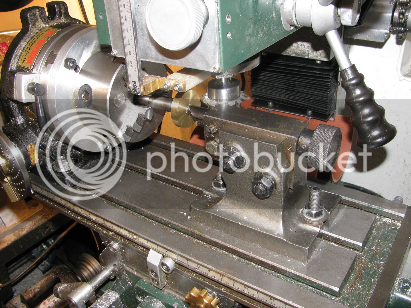
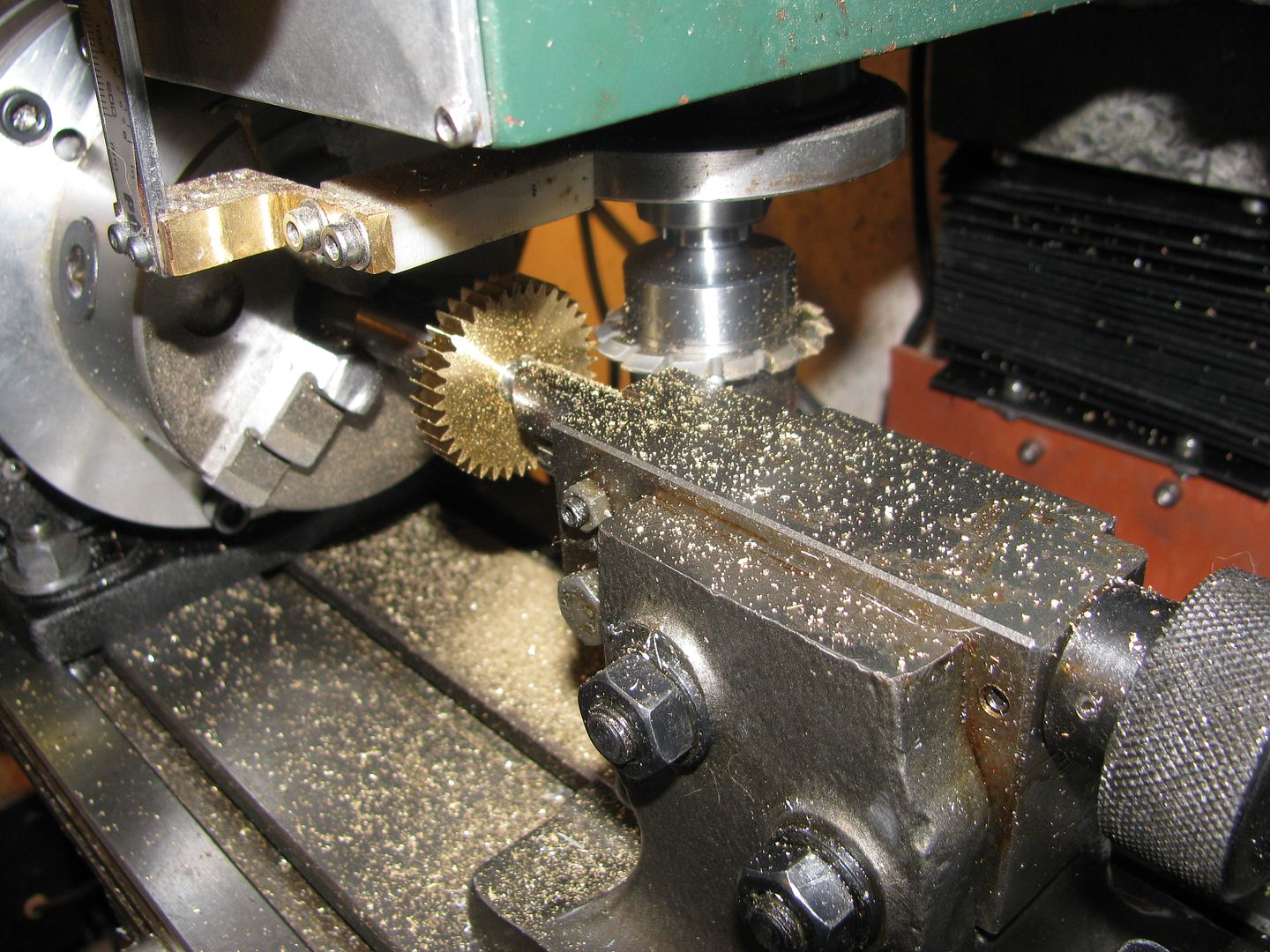
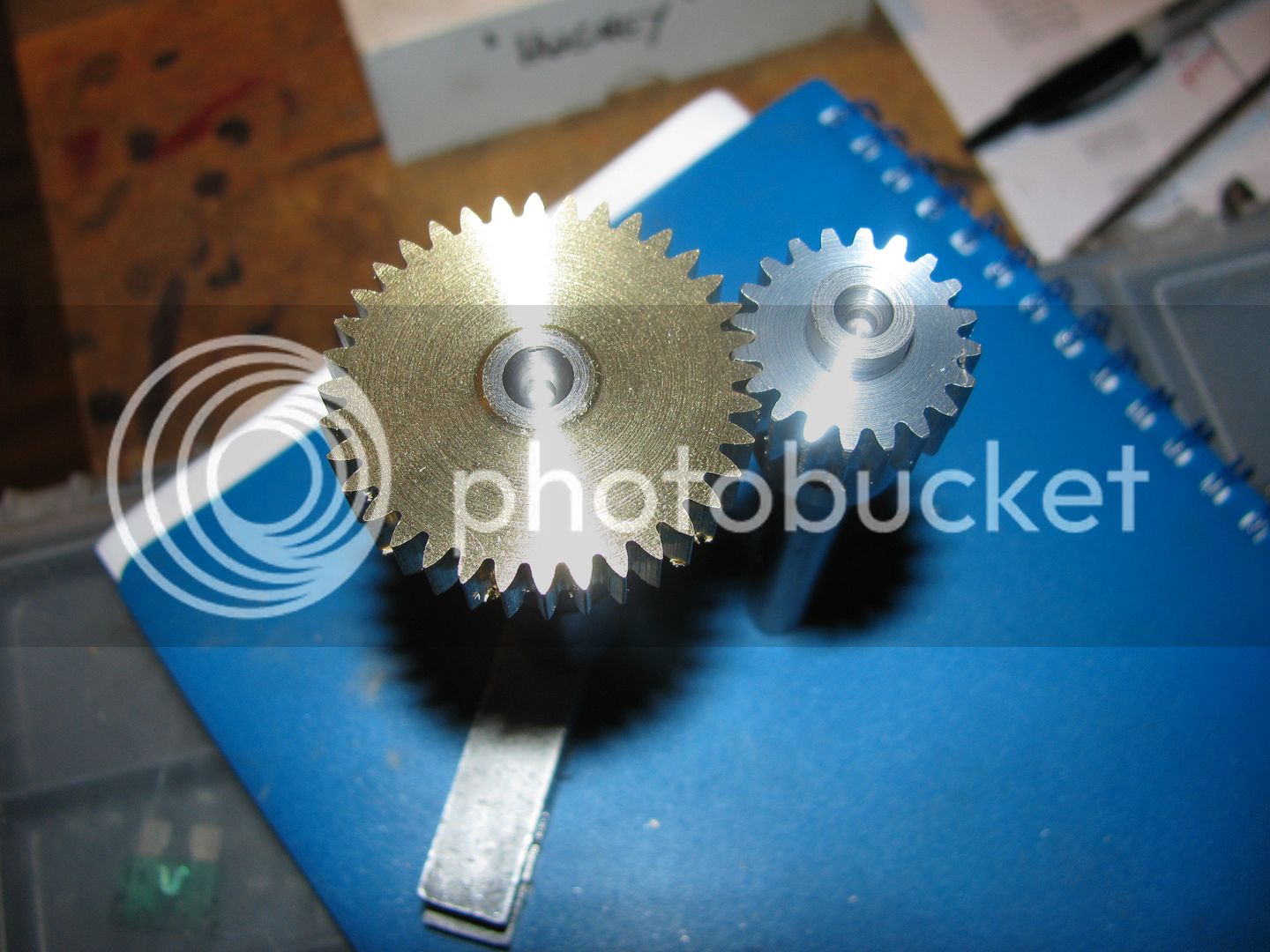
Herbie--I found an old thread I had done in 2012 on gearcutting, and it has 3 good pictures which I will post here, for the sake of "Show and tell". One picture shows the gear blank before any teeth are cut into it (that will be the o.d. of the gear), and shows the entire set-up with the rotary table complete with divider plates, gear cutter in the spindle, and tailstock support in place to hold everything firmly in place while the gear is being cut, and one shows the same set-up after the teeth have been cut into the gear. The third picture shows the finished gear mating with a gear which is smaller in diameter. Note that it is not always necessary to use the tailstock support---However the gear has to be mounted on a stout arbor that won't deflect, and the gear has to set far enough out from the 3 jaw chuck that you don't run the cutter into a chuck jaw as the table is moved left to right. (I did that and ruined a $70 cutter.) The centerline of the cutter is on the horizontal centerline of the gear. With the mill shut off, the mill table is moved in the X axis until the center of the quill and gearcutter is directly in line with the center of the gear blank in the Y axis, but not touching each other. Then move the mill table in the Y axis until the tip of the tooth on the gearcutter just touches the gear blank. I generally hold a piece of paper in between them, and when I feel it "grip" the paper between the cutter tooth and the gear blank, that establishes my '0". I then move the table to the left in the X axis until the gear is clear of the cutter, and move the table in the Y axis until there is 0.0889" interference between the gear cutter and the blank. I use "conventional cutting" not climb milling. That 0.0889" is the "depth of cut", which is the full depth of the space between the gear teeth.. I cut to full depth on each pass, then back the table up so it is clear of the blank, rotate the rotary actuator thru the required number of degrees, lock it, then cut the next tooth. If you have lived a good clean life and never sinned, when you get all the way around to the very first cut you made in the blank, the cutter will just cut air on that pass. If, on the other hand, you havn't lived an exceptionally clean life, or if you have lost count somewhere of how many degrees you turned the rotary table, you will be left with half a tooth---which is very undesireable.


Last edited:
Herbiev
Well-Known Member
- Joined
- Jan 6, 2011
- Messages
- 2,360
- Reaction score
- 310
Many thanks for that Brian. You make it look pretty easy there. The only thing worrying me is the " good clean life" bit. 
Thanks Norm and Hopper. I borrowed the Ivan Laws book on gear cutting and learning quite a bit.
Thanks Norm and Hopper. I borrowed the Ivan Laws book on gear cutting and learning quite a bit.
I have the Ivan Laws book. I read it and it made my head hurt. Old Ivan is probably right in everything he says, but I had the rotary table and divider plates and the mill already, and it was less than two days pay to buy all 7 or 8 gear cutters in the set, along with the arbor. I have used exactly the same gear (as regards pitch diameter and tooth count) set on half a dozen of the small engines I build.
I am following this thread with interest , I have slowly been tooling up in my workshop, and I am almost ready to cut gears for the websters engine , then Brains 2 stroke engine.
I have just found these cutters on ebay and the seller is in the same area as me.
would they be suitable for cutting the gears mentioned above.
http://www.ebay.com.au/itm/Involute...134563?hash=item1c6fe183a3:g:H4EAAOSw8gVX2zdv
Kind regards Matt
I have just found these cutters on ebay and the seller is in the same area as me.
would they be suitable for cutting the gears mentioned above.
http://www.ebay.com.au/itm/Involute...134563?hash=item1c6fe183a3:g:H4EAAOSw8gVX2zdv
Kind regards Matt
- Joined
- Dec 12, 2012
- Messages
- 2,220
- Reaction score
- 1,285
If you are building one of Brians engines then he has fixed the gear centres
which determines DP/Mod etc and no of teeth.This fixes the PCD and pitch
There are 8 involute cutters in a set.Then a no of dp or mod tooth sizes then add different PAs and you have 100s of cutters.The ones you saw on Ebay wont match what you want.Message Brian and confirm what gear sizes and if he standardizes in his designs then 1 set of the correct cutters will suffice
As I am finding out on my learning curve if you are only making a couple of gears to meshs with each other then the only important criteria is centres
and no of teeth or even ratio.
PCD x PI devide by no of teeth will give you pitch.Then you can work out
the depth of cut.Then you can make a non std gear cutter for the application
The problem is we are trying to cut gears that Brian has designed from square one so must use the correct involute cutter or approach the problem from the other end and make 2 gears that mesh at the correct centres with the correct no teeth but not necessarily mesh with other gears
As per all of my drawings on all of my engines--The gears are 24 DP. That is the only set of gear cutters I have. I don't think that gears of any other DP will work, because for a given pitch circle diameter (which must be held so that the center to center of the shafts in the main body of the engine will match what I have designed), the number of teeth in gears of any other Diametral Pitch will change.---Brian
EDIT--EDIT--EDIT---EDIT==EDIT--
A bit more research and snooping around has shown me that my previous statement was incorrect. Gears of a different DP will work and you can hold the center to center distance. The mathematical relationships seem to be such that as long as you hold the pitch diameter of the two original gears (0.625" and 1.25") then the tooth count of the gears will change proportionally. Thus, if you had a set of #32 pitch gear cutters, a 20 tooth and a 40 tooth gear would hold both the correct center distance, and the correct ratio. If you had a set of #48 DP gear cutters, then a 30 tooth and a 60 tooth gear would still have the correct center to center distance and the correct ratio. Matty--I haven't heard of #40 DP gear cutters, but if there are such things, then it would be a 25 tooth and a 50 tooth gear to yield the correct center to center and ratio.---Brian
There is a lot of funky "math magic" involved in which gear cutters you choose to buy. I bought mine early on in my model engine building career, and it was very difficult to know exactly what DP to buy. The DP directly relates to the size of the gear tooth. At about the time I "bit the bullet" and purchased a set of 24 DP cutters, another hobbyist (who doesn't post on this forum anymore) bought a set of 32 DP gearcutters. Both sizes will work on these model engines, but the limiting factor as I see it is as follows. The smallest practical gear that I can cut is a 15 tooth gear. Just for giggles, the pitch diameter is always the number of teeth in the gear divided by the Diametral Pitch, so 15 divided by 24=0.625" pitch diameter. The formulae for determining the outside diameter of the gear blank is "number of teeth in the gear plus 2" divided by the DP.--so--(15+2)/ 24=0.708". The depth of cut is 2.157 (which is a constant) divided by the DP which is 24=.0899", so if you double that and subtract the result, you end up with 0.708"-(2 x .089)=0.530" and that is the "root diameter" or smallest diameter at the bottom of the cut outs between the teeth. If you take another .125" out of that, so that a bushing extended on one side will have at least .062" wall, then the diameter of the bore thru the gear drops to 0.530"-0.125"=0.380" This means that if I do use a 15 tooth gear, I can use my .375" crankshaft. SO---That is why the smallest practical gear I use is a 15 tooth, because it lets me get away with using a 3/8" crankshaft. I can cut as low as a 12 tooth gear, but that means I would have to drop the diameter of my crankshaft accordingly.
Now, let's take a look at what happens If the gearcutter used is for a 32 DP. If we stick with a 0.625" pitch diameter, then the number of teeth in the gear is going to be 0.625 x 32=20 teeth. Assuming a 20 tooth gear, then the o.d. of the gear blank will be 20+2=22 divided by 32=.688". The depth of cut for #32 DP gears is 2.157 (which is a constant) divided by the DP 32=.067" (Which as you can see is going to yield a much finer tooth than my 24 DP cutters.) So---If you take the gear blank diameter minus twice the cut depth, you are left with a root diameter of 0.688-(2 x .067)=0.554". Then if we take another .125" from that to leave a .062" wall on an extended hub, we end up with a bore of 0.429".---SO---With a finer DP like 32, and the same pitch diameter as the gear in the previous post, we can ultimately run a larger shaft, and the gear will have more teeth. The ultimate upshot of all this crazy math, is that with the finer #32 DP you can use smaller diameter gears than with the larger 24DP gears. For engines in the size range which I build, 3/4" bore to 1" bore, the 24DP gearing works just fine. If however your long term plan is to build smaller engines which have gears, then you might be happier with 32DP or even finer 48DP gears.
Matty---I may have lead you astray. A bit more research and snooping around has shown me that my previous statement in post #28 was incorrectexcellent information, thank you for the feed back to my question.
. Gears of a different DP will work and you can hold the center to center distance. The mathematical relationships seem to be such that as long as you hold the pitch diameter of the two original gears (0.625" and 1.25") then the tooth count of the gears will change proportionally. Thus, if you had a set of #32 pitch gear cutters, a 20 tooth and a 40 tooth gear would hold both the correct center distance, and the correct ratio. If you had a set of #48 DP gear cutters, then a 30 tooth and a 60 tooth gear would still have the correct center to center distance and the correct ratio. Matty--I haven't heard of #40 DP gear cutters, but if there are such things, then it would be a 25 tooth and a 50 tooth gear to yield the correct center to center and ratio.-Just be aware that as the DP number gets higher and higher, the teeth become finer and finer.--Brian
- Joined
- Dec 12, 2012
- Messages
- 2,220
- Reaction score
- 1,285
I really enjoyed making them Herbie,more so because they were needed
Some niggles to sort out with the indexing head then I will need a new project
Some niggles to sort out with the indexing head then I will need a new project
Great stuff, Herbie!! We should all have a neighbour like Bazmak!!--Brian
Matty--I just had a look at the plans for the Webster. The gears which are specified are #32 DP , 24 tooth and 48 tooth. Back when I made the Webster, I had no experience with gear cutting so I bought the gears. The pitch diameters of the two gears work out to as follows. The pitch diameter is always the number of teeth in the gear divided by the Diametral Pitch, so 24 divided by 32=0.75"" pitch diameter, and 48 divided by 32=1.5". If we hold those pitch diameters and use the 40DP gear cutters which you supplied the link to, then the gear which has a 0.75" pitch diameter would be 0.75 x 40=30 tooth and the gear with the 1.5" pitch diameter would be 1.5 x 40=60 tooth. If we add half of the pitch diameters together, then 0.375" x 0.75"=1.125", which agrees with the hole centers in the Webster sideplate drawing.--However, I still think that at 40 pitch, the teeth are going to be pretty darn small.---Brian
David Morrow
Well-Known Member
- Joined
- Sep 8, 2008
- Messages
- 227
- Reaction score
- 60
Have you considered any hobby CNC people in your area ? Besides my engine projects, I also make clocks and cutting gears is dead easy with CNC. I use my Sherline CNC or my home-designed CNC router to cut brass parts - the router is actually better. There are two reasonably priced gear programs that are available that I'm aware of - Gearotic and Gear Template Generator -the latter being the cheapest and easiest to use at $26 ( not sure if that's U.S. or Canadian $ ). Create your own gear DXF file and email it to a CNC hobbiest for cutting.
http://woodgears.ca/gear/index.html
[ame]https://www.youtube.com/watch?v=9MycFQKnZkA[/ame]
As for postage, I find that most vendors quote on the fastest delivery method. When I buy from the U.S., I request something much slower and the price comes down dramatically.
http://woodgears.ca/gear/index.html
[ame]https://www.youtube.com/watch?v=9MycFQKnZkA[/ame]
As for postage, I find that most vendors quote on the fastest delivery method. When I buy from the U.S., I request something much slower and the price comes down dramatically.
Mate try www.ronsongears.com.au/ They have a large range and stock on hand. No I don`t work for them
I've purchased gears from TEA Transmissions in Tiaro, Qld. Not sure if their range covers what you need but i was very satisfied with their products and service. Postage/freight costs always a problem though for small objects with a bit of weight to them.
Similar threads
- Replies
- 0
- Views
- 864
- Replies
- 12
- Views
- 3K
- Replies
- 5
- Views
- 3K