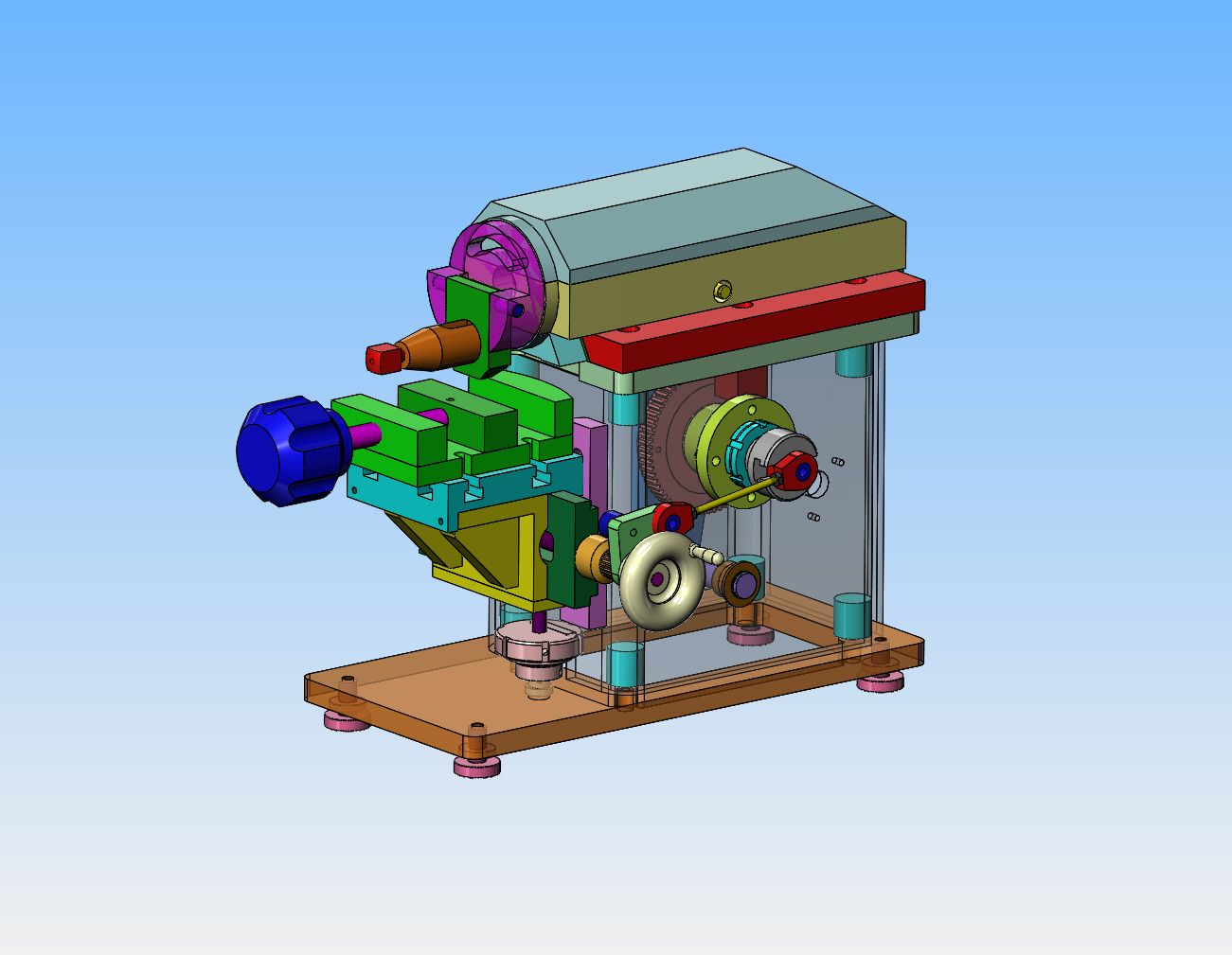
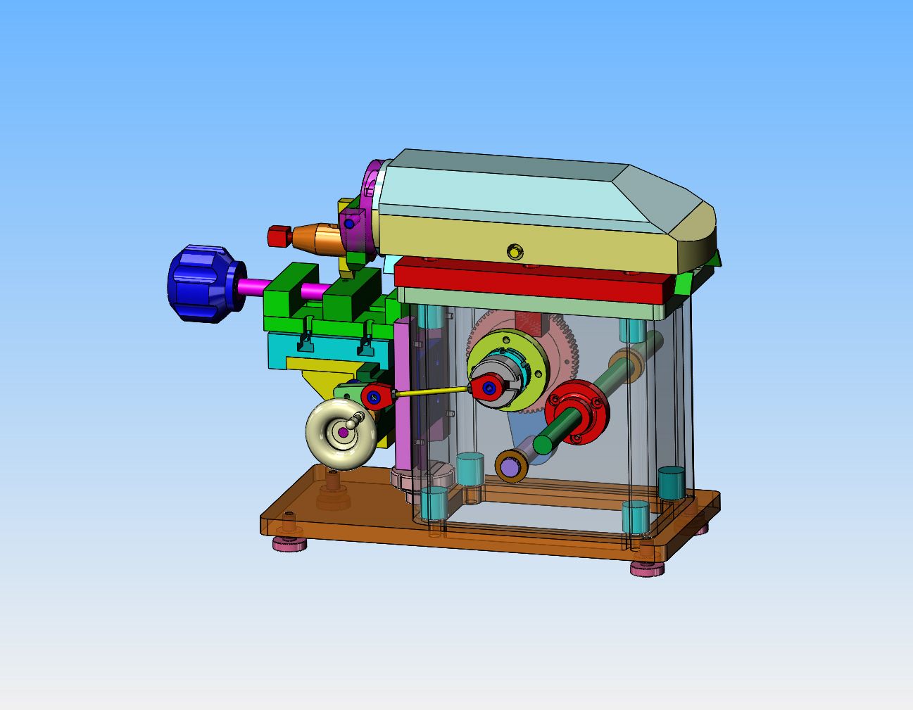
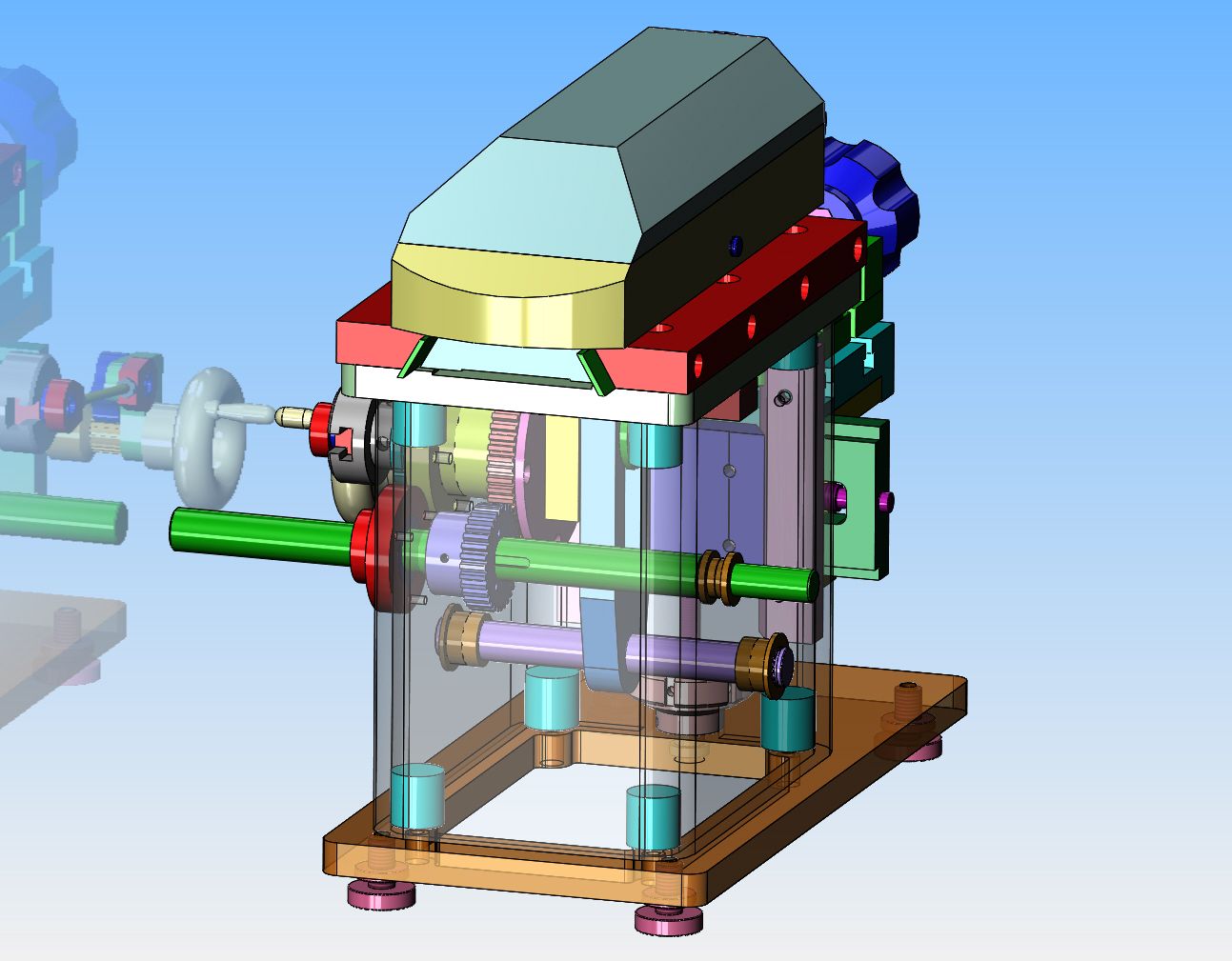
Bazmak-A Model Horizontal Shaper

Home Model Engine Machinist Forum

Help Support Home Model Engine Machinist Forum:

This site may earn a commission from merchant affiliate links, including eBay, Amazon, and others.
It is never to late to learn.--but--You really need to have a good reason. My software is outrageously priced, starting at over $7000 Canadian. For me it is a legitimate business expense, but it is far too expensive for a hobby machinist. There are cheaper versions of 3d software available, but I don't know anything about them. I have received the latest batch of drawings, and will be working on them.--I need a bit more information about your two gears so I can download them from a website I use. Are they a "mod" gear?---If so, what number? ----I am used to Imperial based gears, which go by pitch number, but have little experience with "mod" gears.---I am sure that there must be a number for your gears which refers to the size of the teeth. ---Brian
 
Last edited:
Hi Brian,dont know what the gears are its not important as long as they are the same.The author gave nom od and no teeth.T picked 2 gears I had in a box
spare from my small sieg lathe change gear set.As long as they are both the same and mesh together the mod no is not critical but I assume it can be worked out from no of teeth and od.The important part was to have the large gear at nom 65/66t and od about 67mm.The small gear should have been about 24 t but the smallest I had was 30t,so I just adjusted the centres by meshing and measuring.The large gear is important at nom67od but the small gear can be anything.As I said in the thread I just used what I had.About to finish the last details then we can sort out any minor problems.Just found out how to rotate the drw,MAGIC.Can items be hidden to allow you to look inside??
One thought I had was that if I fit a motor the speed will be too fast but there is room to fit a lay shaft and additional gears Regards barry
 
Right click on any component. This brings up a sub menu allowing you to hide the part, or hide all of the other parts or make the part transparent. down in the lower left corner of the screen there is an icon named "animate". Left click that and see what happens!! Also, try the "explode" icon. You probably have figured out by now how to use the "rotate" icon. It doesn't matter what you do, you won't erase anything. Down in the extreme bottom left there is an icon that looks like a little house named "reset". Click that at any time and everything will be restored to what it looked like when you first opened the assembly. In the extreme lower right you will see an icon named "components' Click on that to see the name of all your components in a list. while the list is open, left click any component on the screen and it will highlight the name of that part on the list. Since I have the "real" Solidworks software, I seldom use the e-drawings viewer, so it probably does many other tricks I don't know about. Edrawings viewer will also open 2 dimensional AutoCAD drawing files which have a .dwg or .dxf suffix on the file name.---Brian
 
Good idea Herbie,will give that a try.12v ?? transformer
Thank you Brian for your input.I am about to post the final details
then hopefully a snagging list from you and we are ready to go
We already have 2 customers so hopefully will keep this thread going
and maybe add improvements.I am thinking about a build description
maybe in the form of a thread with photos and more description than what I already have.Maybe a team build??
 
I've been following this shaper build and I think I would be very much
interested in building one. I've always wanted a shaper but could never
come up the with space or funds. Building a small one, even on twice the
size as you've build Baz would seem to be possible. I'll be following right
along...

Pete
 
I don't think it would to too hard to build a scaled up version. Have to pay
attention to the strengths of the monkey motion parts. A 2x might be too
large actually, I'm starting to think 1.5x. I dunno.

I really want to see what you've done for the cross-head and bull gear and
Brian will have all that shortly I suspect.:cool:

Building one is a very tempting idea.....

Pete
 
Going twice size will give a body of 200 x 300 rhs x about 280 h
I'm thinking of machining capacity in the my Sx2 mill and sc4 lathe might just get the body height in the mill but the ram would be nom 150sg x 400lg
Probably fabricate rather than solid.Will have a general think later
 
That sounds about the right size.... Fabricate everything!!! Much easier
than solid. All simple, straight forward stuff, like the current one.

Pete
 
Barry,

You have made a lovely job of this shaper, and Brians drawings as usual are amazing/ I've got Turbocad 2015 Pro but have not yet managed to draw up some bits I fitted to my Cowells lathe. Work just keeps getting in the way.

You mentioned fitting a motor and a layshaft. I have a small 7" shaper which I refurbished and fitted a new motor to. The way the layshaft and motor is fitted may provide you with a few ideas. See below:

IMG_5026resize.jpg


Regards,

Colin
 
Thank you Colin ,it looks a nice machine.Do you have anymore photos and info on it.Ie rough sizes and weight.Is there any info on the web on this machine?
Just sent an email with info on the first snagging list Brian,almost there
 
Barry,

It is a Corbetts XL 7, although mine does not have any name on it anywhere. Possibly Corbetts made them for others to badge. There is a section on this shaper on the www.lathes.co.uk website. The full spec and copies of advertising are also shown.

I have quite a few photos of the various parts when dismantled. They can be seen in Dropbox via the link below:

https://www.dropbox.com/sh/7pumsta1zbxxnzi/AACd2CxIA9Q65_sMdn79s_Wza?dl=0

Regards,

Colin
 
Barry---I got the table top sorted out, and modelled the bearing housing #37, the 12 mm ball bearing that fits in it, the shaft item #32(except for the keyway) and the cutting tool. I can not find any sketches of gear#34 nor collar#35. I can't find a sketch of bushing #33 either, but I faked it on the bushings. I closed the hole thru the ram to 6 mm to accommodate the 6mm thru shaft. I still am not clear about the 4 holes thru the red dovetails item #10, that hold the brass gibs in place. Their location is dimensioned but I don't know the size. They appear to be threaded full length and counterbored as well. Can you enlighten me about them please.--Also, you show the gibs as being 175 long, while the dovetails item#10 are only 165 long. why is that?
 
Last edited:
Hi Brian,have answered your question by email,meanwhile will post this
problem for everyone.I reassembled the shaper,nudging a few bits and scraping the ways etc.From my previos video it can seen that the autofeed works well.However the angle changes as the table moves up and down and in the extreme the linkage reaches point of no return and jacknifed.Fortunately I was only turning it over by hand so only suffered a bent m8 feed screw (No problem as I was going to make a new one anyway) and a bent 3mm link rod
When I made these parts I did not x 1.5 but left them roughly the same and more in proportion.I am setting out the motion on paper in the high/low and middle posn.Solution is probably
1- remake a new rocker brkt and use the same pawl
1-Remake a new 5mm dia link rod
3-make a new brass spline/ratchet bush.The 8mm thread has a pitch of 1.25mm say 50 thou and has 24 teeth so say a feed of 2thou per stroke I will go slightly larger dia and mill 12 teeth for say 4 thou feed.A couple of other minor mod
which wont affect to any degree what we have already drawn Regards barry
 
Barry--I think that almost does it for parts. You might want to check the position you gave me for that keyway in shaft #32---it doesn't seem to in quite the right place relative to the gear and collar. I think the best way to handle the bolt situation is for you to print out a view of the whole shaper from the e-drawing I last sent you and just write in hand notes with arrows pointing to where the bolts go and what size and type they are, scan it and send it to me. I will put the appropriate bolts in place and that way they will show up on a software generated bill of materials on my general arrangement drawing. As far as your problem with the dynamics of the crank arm go, that is probably best solved by you, as you have the shaper there.
 
Last edited:
Well I sorted the feed linkage,made a few new parts,detailed it all up,and sent the final drgs to brian along with a bolt list
Assembled everything,turned it over a lot and made some chips running it in the lathe.Satisfied I have done all I can at this stage and Brian can upload to
Hmem down load section.Hope someone can make a start
Any questions I will be here.Many thanks to brian for putting in a lot of effort
with great drgs Video to follow
 
To be successful in the above I will describe the std process I always use
It has the same principles as car wheel nuts and guarantees that 2 parts can be taken apart and reassembled as accurately as a dowelled part
As an example bolting the 10mm thk top plt assy to the shaper body
The RHS body has 4x16dia and 2x16sq studs.1 ONLY of the round studs is drilled and tapped thru M5,then all 6 parts are then welded to the body
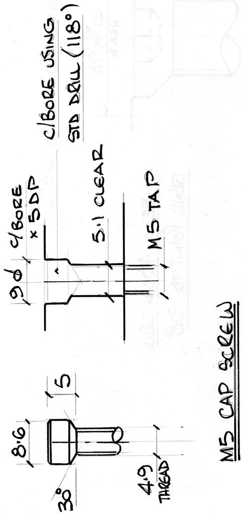
The top plt with the 2 half dovetails bolted in posn is marked out,drilled and c/bored for all 6 holes and the 2 bolted together with a single M5 cap screw
The ply is set accurately in position and diagonal opp hole is spotted thru
A heavy spot almost to the full dia of the 5mm drill.The plate is swung to one side and the second drilled and tapped.The plate is now bolted together with 2 screws.The remaining holes can then be spotted and the process repeated
The two components can now be taken apart and reassembled many times with great accurassy.Standard cap screws have the underside of the head chamfered at 30o and the counterbores are done with a standard drill
see sketch.Takes a bit longer but the results are well worth it
 
Back
Top