Tailstock is now completed - images below.
Looks simple enough but was a lot more work than the headstock.
In case anyone is curious the slots in the base are for locating shims to precisely align to the headstock.
Next step probably to start on chassis - framework.
Charles do you have any photo's of your project? I see you are taking the rocking
cam approach whereas I am using the rocking grinder. No particular reason that is just the way my mind saw it - a different method that should give the same results.
That looks really nice Charles and lovely workmanship and a nice compact design.
My project is briefly on hold while waiting for some 10mm aluminium plate to arrive. I will be working on the rocking beam next which will incorporate the grinding head and motor mount. I should be back into gear in about a week.
Hi all - progress on the cam grinder has been slow due to so many other activities going on at the present time and this will be the case for the next five weeks or so. To keep the thread active I have added a photo on the start made on the rocking beam. The oval hole top left is where the motor to drive the grinding head mounts with the slotted hole to prove adjustment for for drive belt tension. Underneath is a linear bearing to accommodate the ground steel shaft for the rocking beam to slide along to the position required to grind a lobe. Next job is to make the grinding head which will mount adjacent to the linear bearing with adjustment to allow for grind wheel wear. Once this has been done the beam will be trimmed up and shaped considerably to remove excess metal. Not a lot to show this post will will keep adding as things go along.
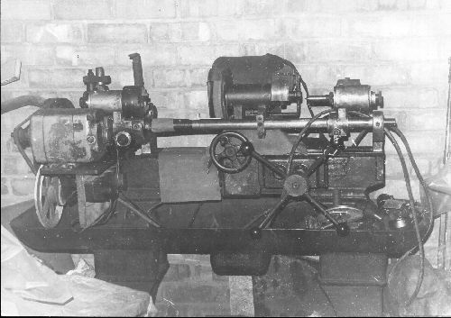
Sorry to hi-jack this thread but many years ago I owned a cam grinder. It was a full size machine but home made and based on an old capstan lathe.
It was originally made for doing cams on racing MG's to give an idea on size. Hang on. Just remembered I have a picture as I described it on another forum.
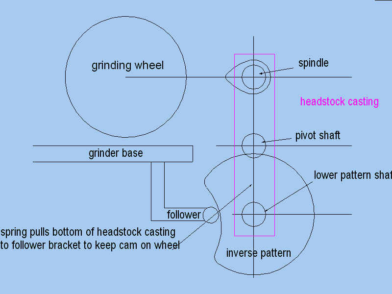
It was a rocking cam type machine as the grinding head was very heavy and it also used an inverse cam as the master cam.
The guy who built it explained that with an inverse cam the master is just a disk machined on the lathe so the base circle is easy to do.
This is the layout how it worked.
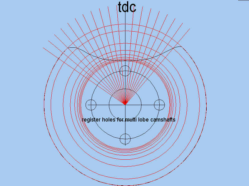
And this is how you laid a cam out.
Using inverse masters means it quite quick to cut and file a master to size.
Thank's for the pic and information John.
I don't regard information placed in the post as "hi-jacking". On the contrary it provides extra information and interest to the post.
Jorgo, I was unable to send a personal reply to your message. Seems to be a software glitch in the personal reply section of HMEM as it listed you as "unseen".
I would love to see some pics of your cam grinder and please feel free to post them here. Sorry to hear of the havoc from the 2013 floods. Are you in Queensland.
Cheers Brian scratch.gif
Sorry for the inactivity over the past few weeks. Grand kid duty and a holiday intervened but I am now back in the work shop and working on the cam grinder again. The spindle housing is complete apart from some tapped holes on the flange to mount a cover for the grinding wheel and an oiler. It will mount into slots on the rocking arm and will have some vertical adjustment for grinding wheel wear. The spindle is also finished apart from clamping washers for the grind wheel. While I am working on this section I will probably next make the motor and spindle pulleys to try and keep some continuity in my brain as I am just designing bits as I go along but I do have a rough over all picture in my head.
Anyways it keeps me off the streets and outa trouble (hopefully).
Pics attached of spindle housing and spindle.
I know there is nothing demanding or exciting in making a simple pulley but thought it may be of interest how I cut a keyway when I don't have any keyway broaches (yet!).What I did was sharpen a piece of HSS the same width as the key in the shaft of the spindle drive motor and mount it in a tool holder central to the centre hole in the pulley held in the lathe chuck and locked in place with the back gear. I then simply wound the cutter through the hole using the feed wheel and taking a small shaving cut of 2 thou. at a time until reaching the desired depth in this case 65 thou. It took a little while (about 25 mins.) but worked a treat and much cheaper than going out and buying a broach. The pulley is made of 6061 aluminium and using this method in steel may be a bit of an ask but without trying I don't know.
Pics of set up and end result.
Here is a recent progress shot. The wheelhead is finished, apart from a wheel guard, which I have not yet decided how to make. The cam drive is also mostly done, including the protractor for setting the relative positions of the cams. It just needs some kind of catch-plate to drive the gear on the camshaft. At the moment I am getting ready to mill the 5:1 cam templates. I am thinking about coolant, maybe air sprayed, and would welcome ideas and experiences.
First your grinder is looking great Charles. It is interesting on the different design approaches with the aim of achieving the same end result. Charles what are the dimensions of your grinder and what is the longest length of cam will you be able to grind. I have been able to spend more time in the workshop lately and things are starting to come together. Main chassis frame is done and rocking beam mounted and I now have something physical in front of me which makes designing the rest easier rather than just a picture in my head. Probably the next step will be the shaft for the master cam blanks and the drive from a reduction gear motor. After that the cam follower mechanism with micrometer adjustment to control the amount of grinding cut. When everything is in place I will then look at removing surplus metal to try and make it all look a bit prettier as well as lighten it up a bit. It doesn't sound like a lot to do but will keep me amused for hours and hours.
Some pictures below - more to come as things progress. scratch.gif
Hi Charles - yes the spindle is adjustable for wheel wear of up to 1 1/2" off of the 4" dia. Your design is a bit more space efficient as my overall dimensions are 23 1/2" wide by 19" deep .The design will accept a camshaft up to 10 1/2" long. Cheers Brian
Hi this is John Samphier from Melbourne Australia. I am building a 4 cylinder engine and to get accurate identical timing a grinder would be most beneficial.
This is the setup for milling a cam template without electronic aids. The clearance ramps, flanks and nose are being milled one degree at a time, using a 0.0001" DTI for precision and a 0.001" DTI to keep track of where we are. Not seen is the clip-board with a spreadsheet printout of offsets, with each of the settings (171 for the inlet cam) being ticked off as we go. An afternoon's work.
Hi this is John Samphier from Melbourne Australia. I am building a 4 cylinder engine and to get accurate identical timing a grinder would be most beneficial.
Package? There are quite a number of model cam grinders to be seen in various places on the web, but as far as I know there is no published design. They are often quite ad-hoc and tend to depend on what motors and materials are to hand.
Mine started with an ex-shower-pump motor.
Charles - what RPM are you going to turn the cam at when grinding. The geared motor I have is 6 RPM at the output shaft but my thought is to speed this up to 2:1 or 3:1 for 12 or 18 RPM. The only info I have been able to dig up was a machine running at 20 RPM. What are your thoughts?
When I made the cam ring for my Forest Edwards Radial (page 3 of HMEM build forum for same) I used an incremental 1deg. 1thou at a time method to cut the lobes and hand smoothed - polished afterwards and it worked a treat. It took a while to get going in the workshop this morning as it was below freezing here last night with a heavy frost and was damned cold. We usually pay more attention to air conditioned cooling down here than heating but occasionally get caught out.
I was in the UK at friends in Suffolk in Sept. 2014 and the weather was perfect as we travelled from Scotland to Cornwall. Just lucky they kept telling us. Cheers Brian :rant:
Hi John - Thanks for your interest - Charles is right about most home build cam grinders being ad hoc almost Heath Robinson type contraptions but all strive to duplicate a master cam into the actual and usually scaled down final camshaft. I could not find any actual plans for one and embarked on the potentially risky "design it as you go" method but so far so good. Building a grinder is no where near as difficult as building an engine so perhaps you may be able to get some ideas from this forum and build one before making the cam for your 4 cyl. engine.
What engine are you building and do you have a build forum on HMEM.
Good luck with your engine - Cheers Brian Thm:
Charles - what RPM are you going to turn the cam at when grinding. The geared motor I have is 6 RPM at the output shaft but my thought is to speed this up to 2:1 or 3:1 for 12 or 18 RPM. The only info I have been able to dig up was a machine running at 20 RPM. What are your thoughts?
Brian, the motor shaft runs at 20 rpm. Messing with available 5mm HTD belt and pulley combinations, I settled on a 2:1 reduction so the cam does a stately 10 rpm. This seems to work very nicely with the finished templates in place, and I think 20 rpm would be fine too, but I would not want to go a lot faster than that.