Old School Barstock 2 Stroke

Home Model Engine Machinist Forum

Help Support Home Model Engine Machinist Forum:

This site may earn a commission from merchant affiliate links, including eBay, Amazon, and others.
At this point I attach a T handle to the piston, using a temporary brass "wrist pin" and using a solution of very little fine diamond paste with a lot of kerosene, lathe not running, I wring the piston in and out of the cylinder by hand, untill I feel it enter freely up as far as the exhaust ports ,then with increasingly more friction as it reaches top dead center in the cylinder. This can be adjusted by just how much lapping I do of the piston into the cylinder. When I am happy with the fit, I then part off the liner from it's chucking stub.---Have I got the sequence right???---Brian

I am in agreement as far as this bit. I would not myself lap the two parts together, but carry on with the external lap to produce the required fit. I would worry that lapping them together might produce too loose a fit. I think the fit you require may well not allow room for abrasive between the parts. I think if you start as tight as you say, you risk a seize-up in the middle of the job. But, I am not very sure of my ground.
 
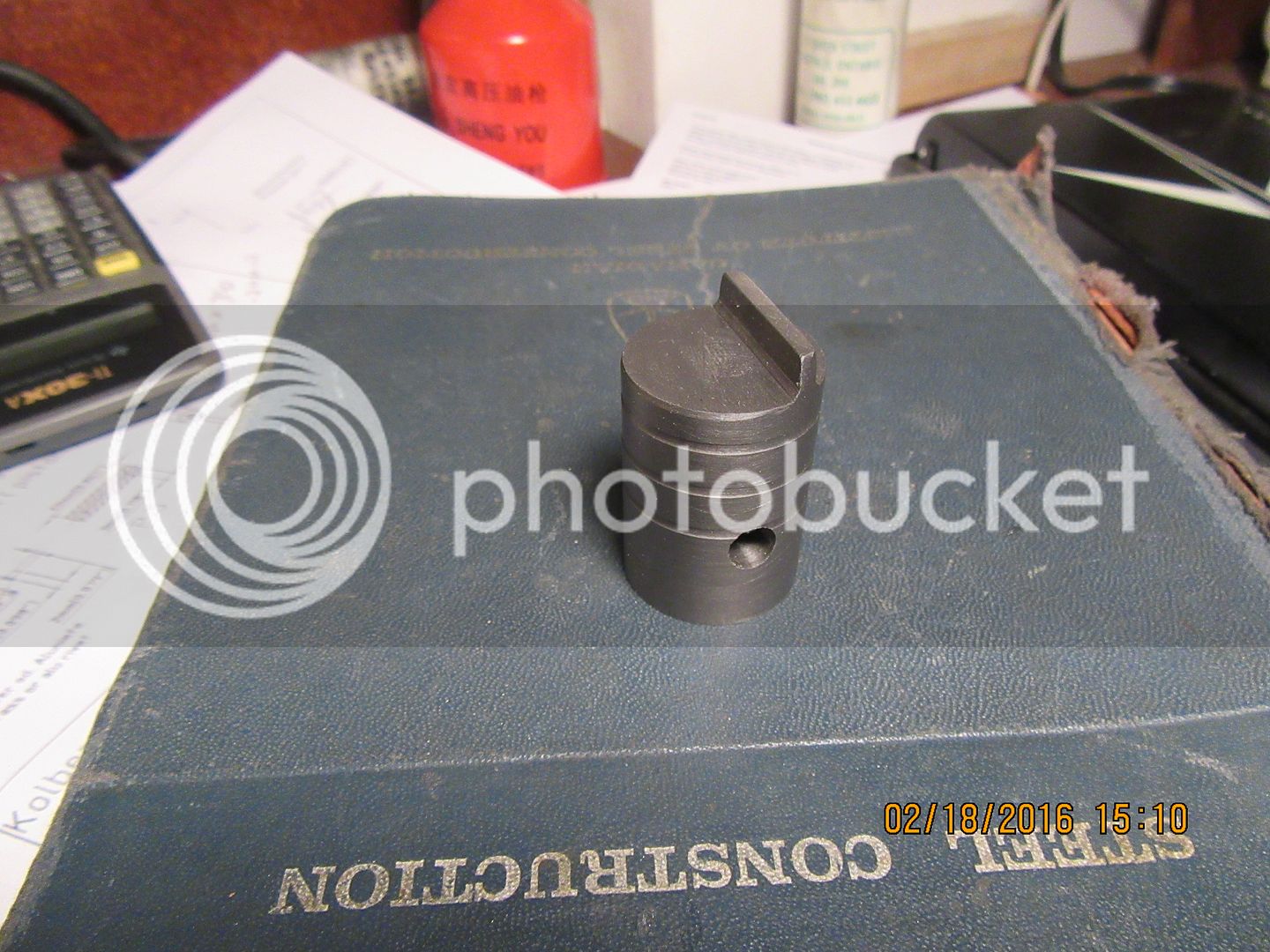
And so it begins---I hadn't planned on beginning to cut metal so soon. But----For the moment I've ran out of intelligent questions to ask. It is plain that for me, the most difficult part of this build may very well be achieving the proper fit between the piston and liner, and the method used to do so. I have ordered a barrel lap, and some "light" diamond compound, and decided that I could build the piston from cast iron and leave it about .002" oversize from the final 24 MM (0.945") that I want to eventually achieve. I have received a lot of interesting and conflicting information so far. The plan calls for three .005" deep oil grooves, while well meaning advisers have told me not to put any oil grooves in.---I chose to put them in, because if I do achieve the fit I want in the liner, I don't want the engine to "seize up" from friction. The original plan has a drip oiler and oil port in the side of the cylinder, so the original designer must have had the same concerns. I have been advised not to use diamond compound by one highly respected and accomplished engine builder. I have been told it really isn't a problem by another equally respected and knowledgeable builder. I had to buy some compound anyways, because the finest compound I currently have is 600 grit, and I need something along the lines of 1000 grit, so I ordered the diamond. i will clean everything out with solvent and a toothbrush when I am finished fitting everything to my satisfaction. The piston shown here is cast iron, "as machined', with no other prep work yet.
 
Brian
Used to build Multistage Compressors with Bores up to 14 inch. All Cylinders after honing were boiled in soapy water ( special Bath )
This opens up the pores of the iron/steel and lets the honing grit out. Have always done it with old Brit Bikes etc with Cast Iron Liners etc and it does make a big difference on the running in and life of parts etc.
Ralph.
 
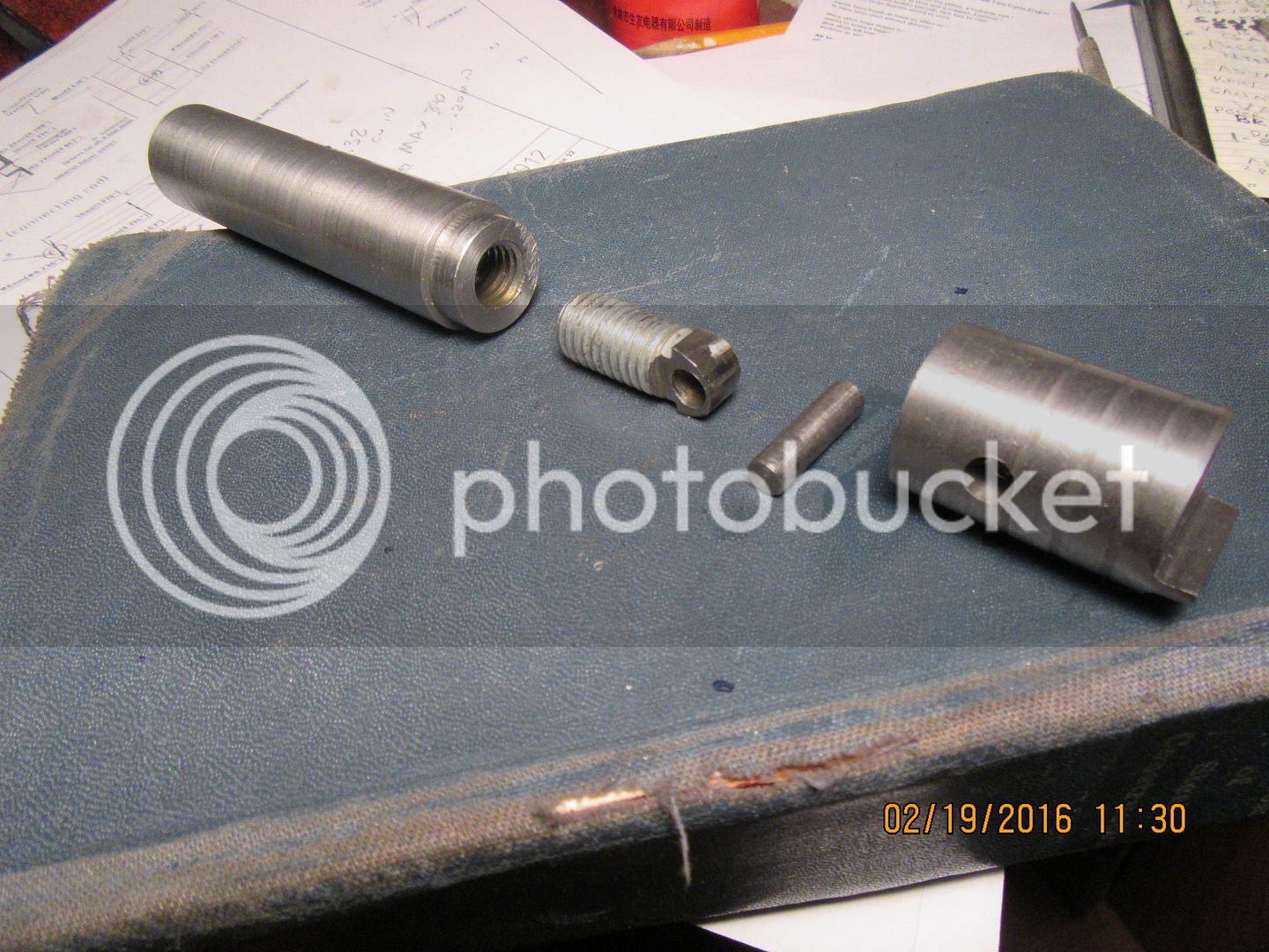
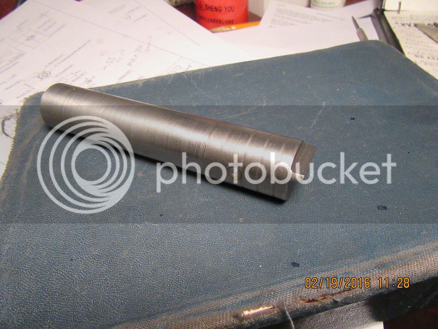
And next, we have something that is almost magic!!! The piston will have to be mounted somehow in order to lap it externally when I go to fit it to the lapped cylinder liner. In the back of my mind, I was thinking about turning a shaft to fit into the counterbore and locking it in there with Loctite temporarily until the piston was lapped, then heating the shaft to release the Loctite. Thanks to help from Jason and Ramon, I have discovered this method. Turn a shaft to slightly less than the finished piston outside diameter, with a step turned to fit into the counterbore in the bottom of the piston. Drill and tap the end of the shaft (I used 1/2"-13). Make up a part that has a matching thread and cross drill it to accept a pin the size of the wrist pin in the piston, and profile the end of it to fit into the piston slot. Make up a dummy wrist pin, assemble the piston, threaded part and dummy wrist pin, then simply screw them to the shaft. It works so well I am blown away!!! The piston probably doesn't turn perfectly concentricaly with the shaft, but that's okay---The lapping procedure is done with the piston/shaft assembly in the lathe chuck turning at a very low rpm, and the external lap is held in your hand.

 
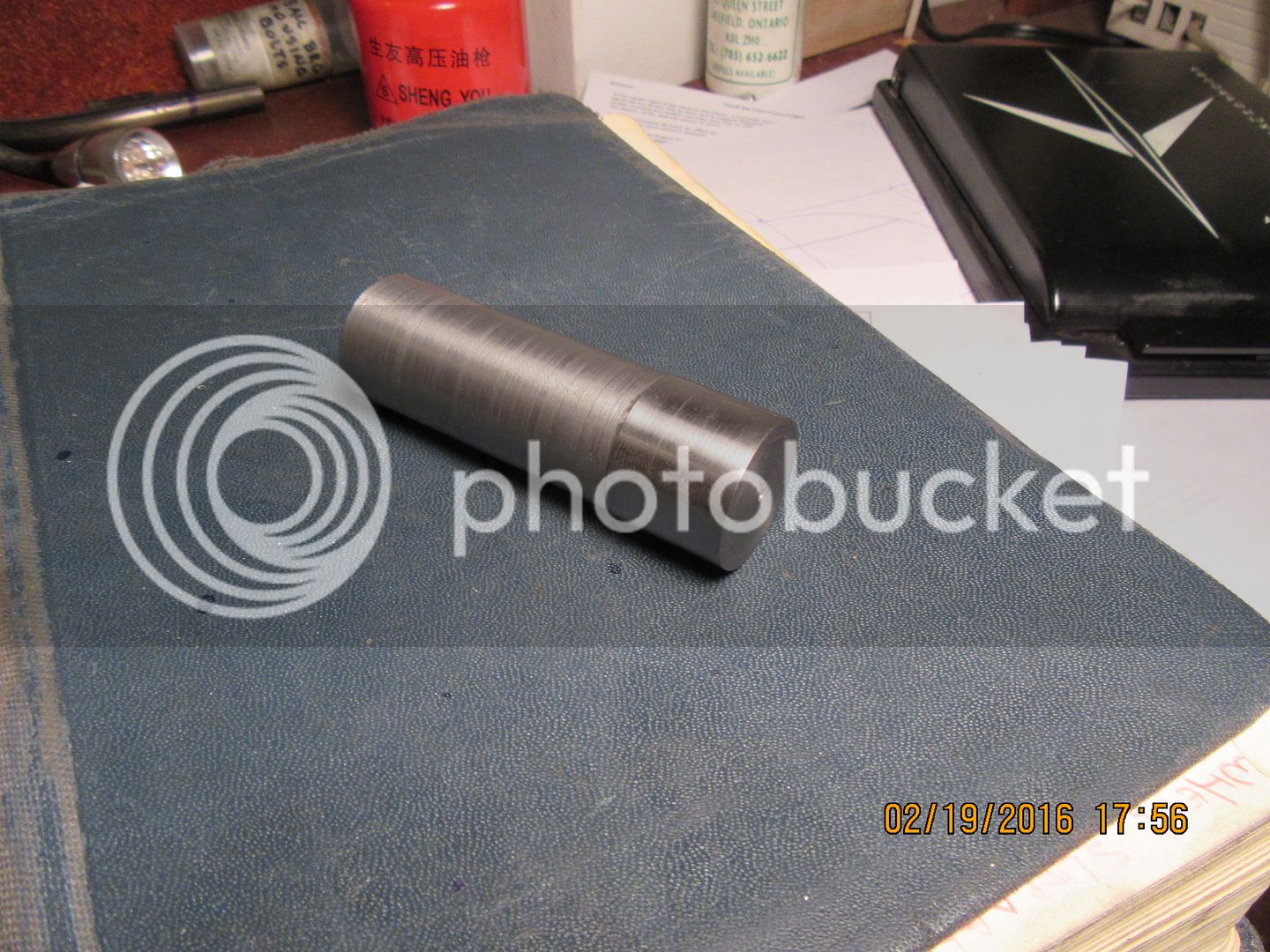
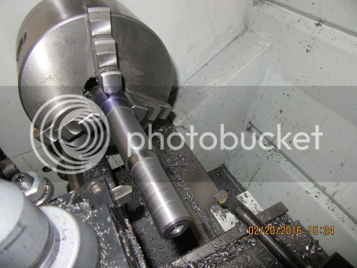
Since I am breaking new ground here, in terms of fits and tolerances, I decided that I needed a plug gauge to let me know when my cylinder liner was getting close to the magic 0.945" (24 mm) inside diameter. Right now my piston is setting at 0.947" diameter, and the last thing I want to do is to turn the bore of the liner too big and have my piston fall thru the darned thing. So, I have made up a plug gauge, that sets fairly and squarely on 0.942". I made it from a piece of 1018 steel, which I have come to believe is the most miserable damned thing in the world to get a good finish on. The reduced area has been turned to 0.900" more or less. The polished end was turned to 0.945" and then finessed down to 0.942" with a strip of 220 grit carborundum paper.---And believe me, for a lousy, stinking .003", that is a LOT of finessing!!! So----My plan now is to set up a piece of 1 1/4" diameter 12L14 steel 1" longer than the finished length I need for my liner in the lathe, drill and ream to 7/8" (0.875") then bore in very small increments until my "plug gauge" will just enter the bore. At that point I will use my new barrel lap to enlarge the bore to 0.945" (Maybe I need a second plug gauge to let me know when I have reached there.---Not sure. I will start out lapping with 600 grit carborundum paste, then move up to the "fine" diamond paste. Then, assuming the bore has cleaned up okay, I will make an external lap and bring the piston diameter down until it enters the liner.
 
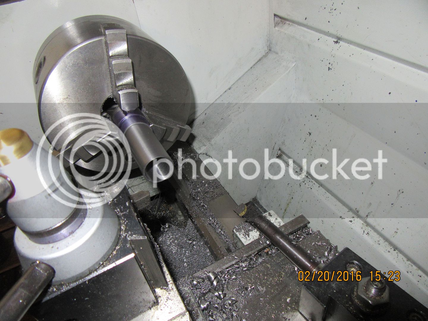
So there we have it--a cylinder liner. I started with a piece of 1 1/4" diameter 12L14 steel. I cut it 1 1/8" longer than the finished length I needed. I chucked it up in the lathe, and had 1" in the jaws and the rest stuck out. I know that is an uncommon amount of stick out, but I wasn't going to be taking any heavy cuts. I drilled out the center all the way through with progressively larger drills until I got to 0.780" diameter, then used the brazed carbide boring bar to take it out to the required diameter. The lathe was running at about 280 rpm. I don't have any kind of instrument to directly measure the bore, but I do have a set of those expanding inside things (not sure what they are called) that you insert into the bore in a collapsed state, then loosen the handle to make them spring out to both sides, then lock them with the handle and take them out and measure them with a micrometer. I was taking .010" deep radial cuts until I seen that I was closing in on my targeted bore of 0.942", then took many smaller cuts with much measuring until I got to a point where my plug gauge would just start into the hole. (second picture) I then turned the outer diameter to first 1.142" and 1.063", and hit the numbers within 0.001" which is close enough for a Loctited liner. I haven't parted the liner off from the parent material yet, because I need that "stub end" to hold it in the 3 jaw chuck which is bolted to my rotary table while I cut the ports and the sparkplug access hole. The lapping won't begin until after the ports and sparkplug holes are cut and the stub end cut off.

 
I don't have any kind of instrument to directly measure the bore, but I do have a set of those expanding inside things (not sure what they are called) that you insert into the bore in a collapsed state, then loosen the handle to make them spring out to both sides, then lock them with the handle and take them out and measure them with a micrometer

Telescopic gauges
 
Telescoping gauge!

Pete
50/50 snap or telescopic

snap gauge.jpg
 
A sales catalog??? Come on! At least look it up from a solid source.

Here's from one of the oldest, most respected, companies:

http://www.starrett.com/metrology/m...isplayMode=grid&itemsPerPage=24&sortBy=wp/asc


http://www.starrett.com/metrology/m...isplayMode=grid&itemsPerPage=24&sortBy=wp/asc

And here's from Wiki...

https://en.wikipedia.org/wiki/Snap_gage

Just Google it up, you'll find hundreds of citations...

Been using 'em for over 50 years.

Pete

If this is all you need to have a good day:rolleyes:
print the adds and look at them tomorow :rolleyes:
thing`s have change with age
 
Guys--Please--I don't care that much what they are called. I know I use them, and they aren't great but they get the job done. They require a special skill set to use them and get repeatable readings.
 
Guys--Please--I don't care that much what they are called. I know I use them, and they aren't great but they get the job done. They require a special skill set to use them and get repeatable readings.

I usually put the gauge into the hole at an angle with some friction of the lock. The gauge will naturally find the largest diameter in the bore. By swivelling the gauge through the true diameter, the friction is sufficient to allow the gauge to be removed from the bore and the lock tightened before using a mic to measure the bore diameter.

Example. With the bore in the lathe, put the gauge in the bore with the handle pointing down at about 30 degrees. Have some lock on and lift the handle to 30 degrees upwards. Withdraw gauge, lock and measure.

Dave
The Emerald Isle
 
I'm waiting for my barrel lap to come in to my tool supplier, but decided I could build a lap for the outer diameter of the piston while I waited.
 
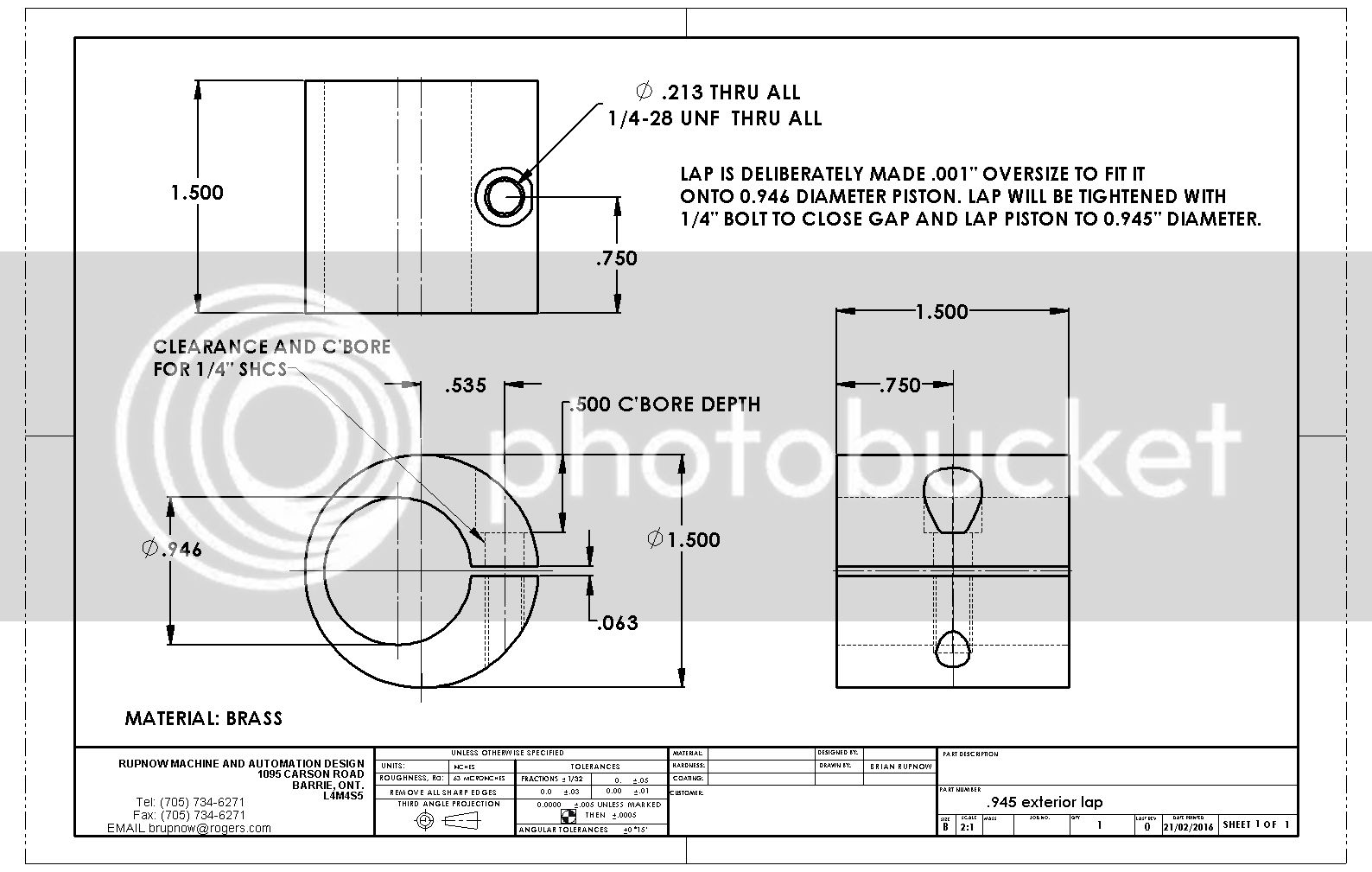
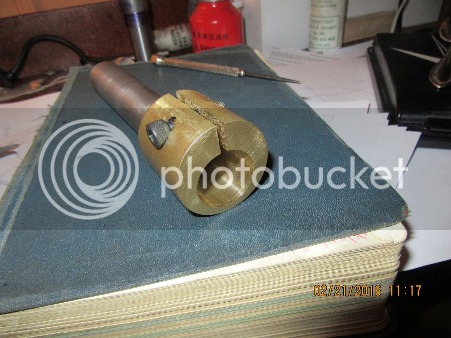
This is the finished brass lap for the o.d. of the piston. It is a tight fit. I bored the lap to exactly 0.946", but when I put the saw-cut in it, it closed up to about .942, while the o.d. of the piston is about 0.947". this doesn't alarm me too much, because the first .001" or .002" will come off very quickly, as the lapping compound is basically knocking off the high ridges left by machining, not only on the outside of the piston, but also on the inside of the lap itself. I will start the piston with 400 grit, then move up to 600 grit. However, I won't do any of the lapping on the piston until I get the cylinder lapped to size, then I will lap the piston independently until it just slides into the cylinder bore.
 
I am watching your progress closely Brian as I am up to this point in my Boll Aero build.

I have a question I am hoping you or another knowledgeable member can help with. I am about to make a similar external laptop for my piston, but I don't have any suitable brass. Do you think aluminium would work, or would it simply be too soft?

Loving following along as always!

Cheers
James
 
Roboguy---I am certainly no authority on this, but I think aluminum would work as well as brass. If you have the aluminum already, give it a try. If it works you've saved some money. If it don't, then you're only out a couple of hours of time.---Brian
 
Back
Top