Oscillating I.C. Engine

Home Model Engine Machinist Forum

Help Support Home Model Engine Machinist Forum:

This site may earn a commission from merchant affiliate links, including eBay, Amazon, and others.
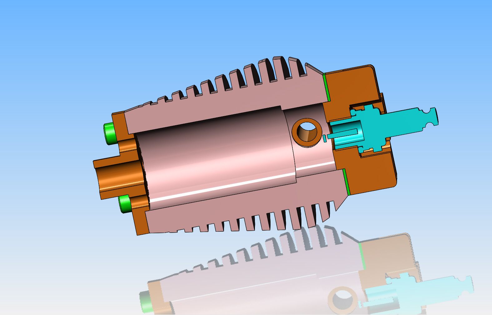
Okay---the jury has decided. It is going to be an aluminum cylinder with pressed in steel pivots. I have had to do a few strange and wonderful things to accomplish this. The engine as originally designed had a 4.5:1 compression ratio, and a 1" bore. I determined that when the piston is at top dead center, it stops .050" before the side of the pivot hole in the side of the cylinder. So--I reduced the diameter of the bore to 7/8" from the outboard end of the cylinder to .025" past the hole for the pivot. That gives me an extra .062" of wall thickness to hold the pressed in pivot pins in place, and still leaves .025" clearance between the top of the point where the 1" diameter piston stops it's upward travel and the beginning of the reduced bore diameter. This of course increased the compresion ratio to a higher number. Fortunately, the original design had the inside of the cylinder head extending down into the cylinder itself by a considerable amount. I was able to shorten this intrusion into the cylinder by a sufficient amount to restore the compression ratio to what it should be.
 
I just had an amazing idea. In the cross section of the cylinder, you can see the extra "breather holes" cut in the cylinder con-rod guide to prevent pulling a vacuum when the piston is on it's way up from dead center.-This means that every time the piston travels down, a puff of air comes out of those holes. if I went absolutely steam punk crazy, and made up a couple of 180 degree u-bends in brass hollow tubing and fitted them into two of the top holes, they would blow a blast of air over the cooling fins with every revolution of the crankshaft, as the piston travelled down in the bore!!
 
That's it!! All of the modelling is finished. I know the design has evolved since I started, but that is the nature of design. Sometimes I have to design a thing and look at it for a while before I decide whether or not it is practical or pleasing to my eye.---or "do-able" on conventional machine shop tooling. I don't know when I will actually start building this engine, but it probably won't be too far off. I will build the cylinder first, because that will be the trickiest bit of machining.---And Oh yeah--The jury is still out on those inserts in the flywheel, but they would create air flow!!!---Brian
 
Well, THAT was a very interesting hour!!! My goodness, I love that mounted digital caliper.-I have never cut such accurate, consistently spaced fin grooves before. Nothing jammed, nothing broke, and I cut them at 215 RPM which is faster than I have ever used before, using my HSS parting tool and lots of dripped on cutting oil.
 
Nice job Brian...if that is the toughest part the rest of the build should be a breeze!
 
Nice one Brian,will watch this thread with interest.If you would supply drawings
i would like to make this my first IC engine.Looks good and nice and compact
Keep posting. Regards barry
 
Baz--You are a very brave man!!! My suggestion for a first i.c. engine is the good old tried and true Webster. If however, you have a desire to live dangerously, at least wait until I finish mine to see if it will run or not!!:eek::eek: I know of at least two that were built to the original design. One by Philip Duclos, the original designer, and one by a fellow in Florida. I have made a few changes to the original design, and I have never had it confirmed that the original engines ever ran---well or otherwise.---Brian
 
Cylinder has had one end cut off and is bored to 1" diameter. Actually, it has two sizes of bores, 1" where the piston travels, and 7/8" in the actual combustion chamber. The holes have been drilled and tapped in the visible end. I always have to be very careful on a part like this that I don't "paint myself into a corner" and find that there is nothing to hold onto to do farther stages of machining.--I can now make a 1" diameter arbor that has a flange in the middle for bolting to the end of the cylinder which is drilled and tapped. On one side of the flange, the arbor extends into the bore of the cylinder, right up to the step in the bore. On the other side of the flange, it sticks out a couple of inches so I can hold it in the chuck on my lathe to part of the other end and into the chuck on my rotary table to machine the flats on each side and the through holes.
 
So far, we're right on track. I know this cylinder is making things picture heavy, but it is a multi-step operation, and the new-bees appreciate the step by step pictures. The next thing will be a trip over to the mill to tap the bolts in the cap end, and then into the rotary table to mill the flats and the drill/ream the pivot holes. I have a bit of a sneaky feeling that this aluminum may be too soft to run without a liner, but Hey--Nothing ventured -Nothing gained!! I've checked it out already, and if it is too soft, I can but in a cast iron liner and run a 7/8" piston.
 
Hey Brian, Looks great so far. I have no doubt it will run. I did see a running example at Cabin Fever 4 years ( I think ) ago. I looked through my photos of that trip but couldn't any pics of it.
 
The cylinder is finished. all went very well, with no mishaps, until when I was taking it out of the mill I realized that the flats were cut 45 degrees out of phase. I thought briefly of committing Hari-Kari, but then realized that this was a good thing. The pressed in steel pivot pins will now be directly under two of the head bolts, so I can extend the thread right into the steel pivots and that will act as some additional "security" to keep the pivot pins from trying to escape, and will give more thread for the two head bolts directly over the pivots. Setting on one side of the cylinder is a cut off section from the piece of aluminum I started with ---it will become the cylinder head. On the other side is a chunk of 660 bronze, which will be the con rod guide on the other end of the cylinder.

 
No matter how I rationalized it, it just wasn't going to look good. So--I put in a second set of tapped holes in each end, and offset the hole pattern 45 degrees from the flat areas. The set of holes I don't use will be covered up by the caps bolted to both ends of the cylinder. I have an "undersize" 3/8" reamer (0.3735")which I used to ream the cross hole of the cylinder. All of my cold rolled round stock is .001" undersize, so I turned the pivots from 01 drill rod to an exact .375", coated them with "press fit" #648 Loctite and after putting a 7/8" diameter slug in the top of the cylinder to guard against flattening it, I pressed the pivots in with my 1 ton arbor press. They went in HARD!!! I now see that I have milled away more fins on the sides than I intended to, but I'm going to have to live with that. That is one of the dangers of designing your own stuff and having two or three "iterations" of the same part.--You lose track of what you are doing when you actually make the part. Overall, though, I' liking this!!

 
Have you thought of putting a shoulder on the valve side pivot shaft? That way you would not have metal to aluminum wear.

Just a thought.
 
And so, the end of a good day. Making parts, fixing mistakes, and taking time out in the middle of the day to put up a clothes line for my oldest son's mother in law. (And yes, there is a story to that, but I won't tell it here!!) That's just a dummy con-rod sticking in the brass con rod guide. If a person had a yard of that 660 bronze, you could trade even for a small island in the Caribbean. If I sleep tonight and goodwife doesn't have any plans for me tomorrow, I'd like to make the cylinder head.
 
Back
Top