TorontoBuilder
John
- Joined
- Jan 4, 2013
- Messages
- 359
- Reaction score
- 84
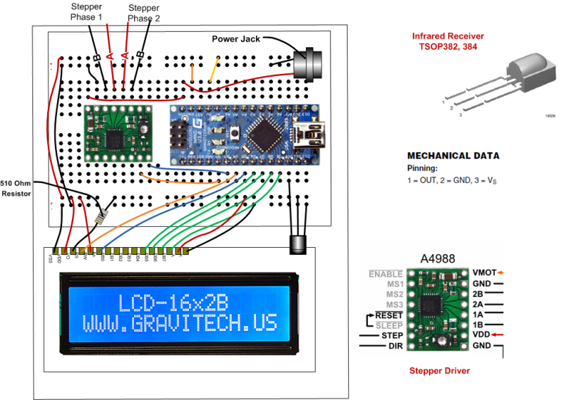
Here is a link to yet another version of an Arduino based index head
I have a little different "user interface" - the way of entering the steps, degrees and such. I'd like to hear/see how yours performs under the mill... I'm haven't fully tested mine yet and am wondering if the steppers will give the needed accuracy for (light duty) gear cutting.
=Alan R.
Nice work Alan. I had wanted to use a rotary encoder on my project but thats too much learning for my first attempt... the addition of divisions and jog functions is great... will you post some arduino code so people can learn more from your project?
John


")