


Another resurrection post, and if most people have seen it before, please spare a thought for those who maybe haven't.
##########################################################################
This is by no means my idea, I saw one demonstrated a few years back and decided it would go onto my tuit list
Up until now I have used a bit of hardwood mounted into a toolholder, but decided the other day I needed to make a proper one.
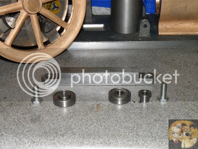
The things required were a lump of bar that will stick out either side of the toolholder (if using a QCTP) or you would make it single ended if using a normal toolpost, a couple of reasonable sized ball races, mine were 3/4" diameter, a couple of bolts, mine were 6mm, you need something fairly substantial to take the strain, and a bit of bar to make the top hat spacers from.
The bar was cut down for a nice fit in my toolholder, 16mm square. It was then machined down by the thickness of the bearings and across by about 3/4 their diameter
The top hats were made to a couple of thou longer on the part that goes thru the bearing and the flange was just larger than the diameter on the bolt heads. It was drilled thru the middle 6mm, to fit the bolt. You could use two top hats for each bearing, as long as they didn't meet in the middle. Anything to stop the bearing becoming 'trapped'.
Holes were drilled and tapped 6mm in the position where the bearing didn't quite hit the back shoulder and hung out of the end of the recess, half way across the width of the square bar.
It was more difficult to describe it than make it. Just have it so the bearings stick over the end bit. I also reduced the thickness of the bolt head to about half, just to give a little more room if things get tight.
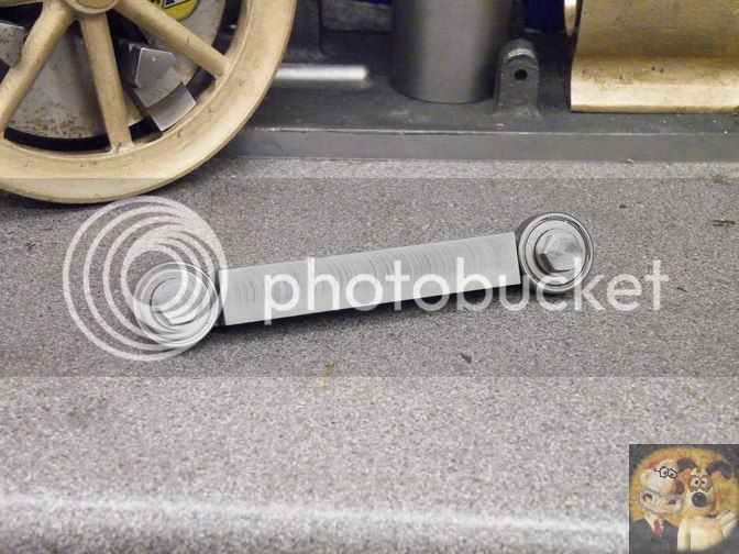
This is how it should look when assembled.
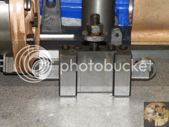
Mounted in the toolholder, with a bearing either side.
It should be set to centre height when working, but I am showing how it is used.
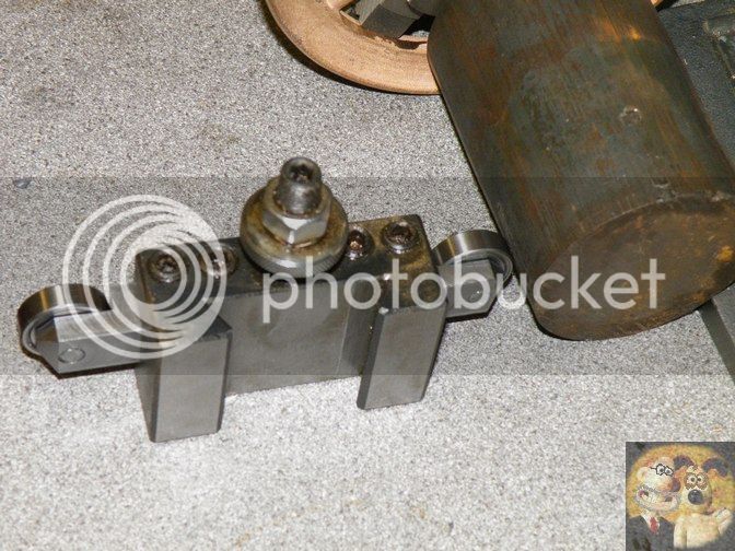
With the part mounted into or onto the chuck, with the jaws just 'tweaked' tight, the ball race is brought into contact with the face that requires straightening up. With a slight nudge from the tool, the part should move into a much truer running position, then you tighten up the jaws. If say you were holding a disc in the jaws, by nudging, you should be able to get it running fairly true, if not spot on.
By swinging the tool holder the other way, the other ball race can be brought into operation to true up those wobbly bits of metal held in the jaws, before fully tightening up.
Please don't try it with square or hex bar, it won't work very well.
John
##########################################################################
This is by no means my idea, I saw one demonstrated a few years back and decided it would go onto my tuit list
Up until now I have used a bit of hardwood mounted into a toolholder, but decided the other day I needed to make a proper one.
The things required were a lump of bar that will stick out either side of the toolholder (if using a QCTP) or you would make it single ended if using a normal toolpost, a couple of reasonable sized ball races, mine were 3/4" diameter, a couple of bolts, mine were 6mm, you need something fairly substantial to take the strain, and a bit of bar to make the top hat spacers from.
The bar was cut down for a nice fit in my toolholder, 16mm square. It was then machined down by the thickness of the bearings and across by about 3/4 their diameter
The top hats were made to a couple of thou longer on the part that goes thru the bearing and the flange was just larger than the diameter on the bolt heads. It was drilled thru the middle 6mm, to fit the bolt. You could use two top hats for each bearing, as long as they didn't meet in the middle. Anything to stop the bearing becoming 'trapped'.
Holes were drilled and tapped 6mm in the position where the bearing didn't quite hit the back shoulder and hung out of the end of the recess, half way across the width of the square bar.
It was more difficult to describe it than make it. Just have it so the bearings stick over the end bit. I also reduced the thickness of the bolt head to about half, just to give a little more room if things get tight.
This is how it should look when assembled.
Mounted in the toolholder, with a bearing either side.
It should be set to centre height when working, but I am showing how it is used.
With the part mounted into or onto the chuck, with the jaws just 'tweaked' tight, the ball race is brought into contact with the face that requires straightening up. With a slight nudge from the tool, the part should move into a much truer running position, then you tighten up the jaws. If say you were holding a disc in the jaws, by nudging, you should be able to get it running fairly true, if not spot on.
By swinging the tool holder the other way, the other ball race can be brought into operation to true up those wobbly bits of metal held in the jaws, before fully tightening up.
Please don't try it with square or hex bar, it won't work very well.
John


