Model Woodsplitter

Home Model Engine Machinist Forum

Help Support Home Model Engine Machinist Forum:

This site may earn a commission from merchant affiliate links, including eBay, Amazon, and others.

Brian Rupnow

Design Engineer
Project of the Month Winner
Joined
May 23, 2008
Messages
14,969
Reaction score
8,247
Location
Barrie, Ontario, Canada
As far as I am able to determine, no one has built a model wood splitter. A google search on wood splitters show two main types, either hydraulic (which are not suitable for a model, in my opinion), and electric screw type which might hold some promise. Then of course there is the cone shaped threaded splitter which bolts to a tractor wheel and screws itself into a block of wood, bursting it to split it, and the heavy revolving flywheel with an axe head mounted on it, which looks like a total suicide machine. I have seen one example of a steam driven wood splitter, which worked well, but I doubt that it would scale down very well.
Model engines simply don't have much torque. One of the primary things that a model woodsplitter would need would be a huge torque multiplier, and with torque multiplication, things slow down dramatically.
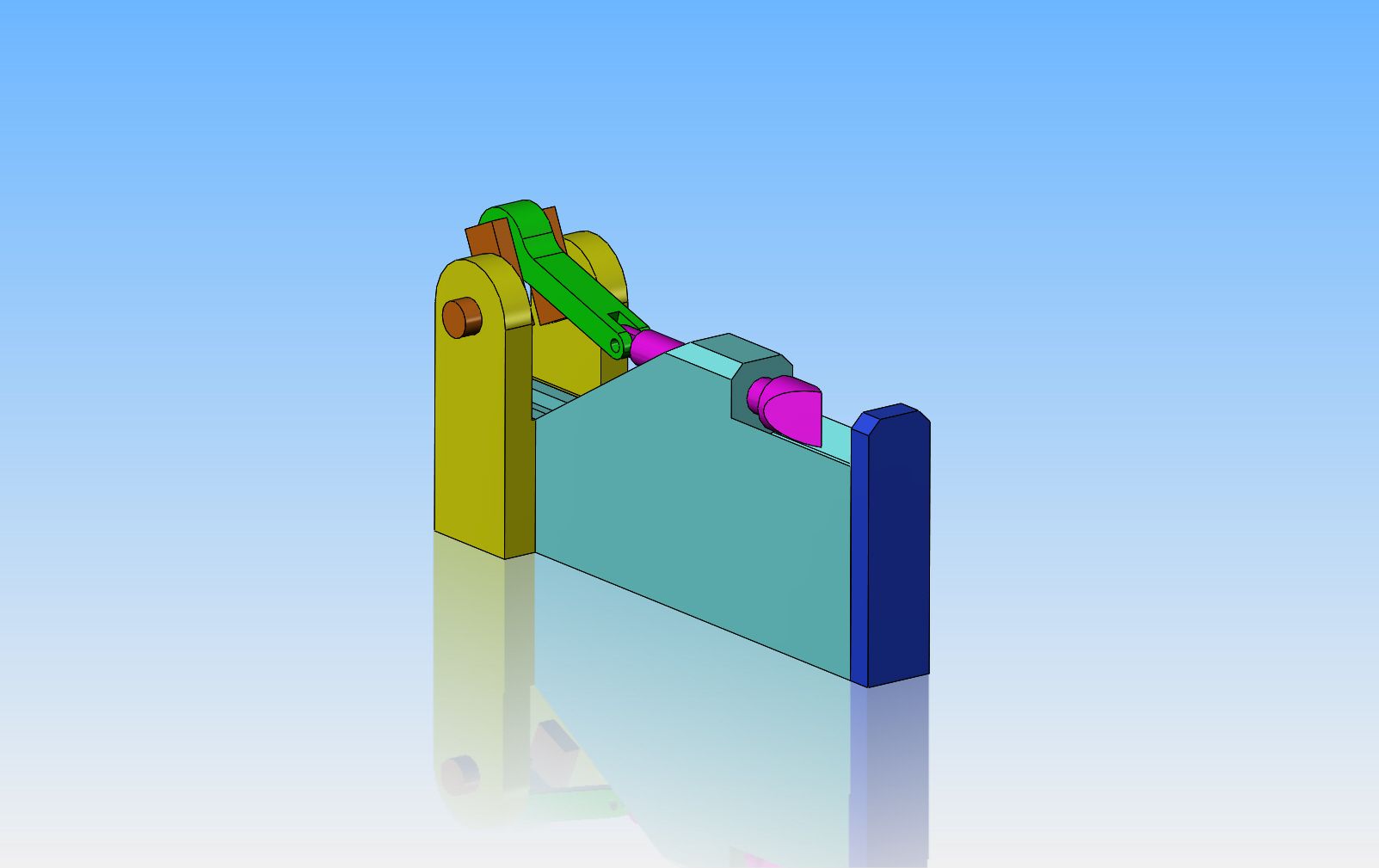
I have a couple of ideas floating around in my head, one involving a rack which is pushed forward incrementally by a sprag driven from an eccentric, and one which had a heavy flywheel with an eccentric on both sides driving "pusher arms".I want to split wooden logs 1 1/2" long, and prefer to split them in one full movement of the splitter, not incremental units.
 
Of course, the wood splitting action would have to be controlled by a hand lever mechanism, so it would only split "on demand", and then only one cycle. Nobody wants a finger chopped off while removing the split piece of wood and putting a new piece on the splitter.
 
I have been setting designing in my head for two hours, and have decided that even though model engines don't have a lot of torque, they can spin a massive flywheel, and generate tremendous inertia. If one can then gear down the rpm of that big flywheel and use a dog clutch to engage/disengage an eccentric with pusher arms, that will work, and yes, I'm pretty sure that it can be set up to "go home" after each cycle and wait to be activated again. The dog clutch is something I haven't designed before, and as an added attraction, the mechanism is going to have to disengage the dog clutch automatically and return the handle to the disengaged position after each cycle.
 
Hi Brian,
This idea sounds great. I like unusual/unique models. Love to see you build this one. I wonder how many working model splitters have actually been made, let alone scale model splitters. You got me thinking (ok:hDe: everyone) maybe using multiple flywheels of differing sizes weights to create the energy needed to spit logs, and/or a combination of similar/same size and weight flywheels with maybe smaller and larger sprockets attached to their sides.
I imagine the first flywheel driven off the, lets say steam engine for example, could use a rubber o'ring but the last flywheel would need some serious drive system. Probably need some sort of clutch to get it all going..
Gear it so the final output speed, rpm is something useable... Just thoughts..
Then there was the thought of some design of lockout lever that had to be pushed/pulled and held, at or before a certain point to initiate the stroke of the splitter. But the lever has to be activated before that point or the user then has to wait for the next time round and try do it earlier to get it to start the splitting stroke. Otherwise if the lever is left untouched, the splitter head will not move from its ready to split position.
Then I re-read the word 'lever' you wrote and started thinking torque multiplication via leverage?? This principle will also reduce the engine input speed down to something slower and more useable for the final drive of the splitter head.. I dunno.. All just suggestions/thoughts.
Wow, the possibilities, I will be watching this one!
Better split now before my head explodes *bang* ;D
Paul
*Started typing a reply to your 2nd post. Posted, then saw your 3rd post. I think there is a saying, 'Great minds think alike'. Thm:
I think your going to have to spend a few more hours than 2 before this all falls together or any decisions are 'permanently' made .Go easy, don't rush in too fast. Keener than ever to see this now!
 
Last edited:
Hi Brian, metal power presses work on a very simple principle similar to what you describe. A large flywheel with a simple engagement, and return to the start after one cycle. May be worth googling metal stamping presses.

Paul.
 
Swifty--You're right!!! I had kind of forgot about them. The big trick will be in the dog clutch and return to home position.
 
Swifty--You're right!!! I had kind of forgot about them. The big trick will be in the dog clutch and return to home position.

They are very simple Brian, I tried a quick Google to see if I could show the mechanism but could not find one. They use a simple slot in the flywheel near the bore and a spring loaded key that jumps up and engages in the slot as the flywheel turns. As the flywheel rotates there is a spiral taper that pushes the key back down and a simple holder that keeps it down until a lever releases it again.

Paul.
 
I suppose a fair amount of trial and error experimentation would be required to zero in the energy required to split the log.
To that effect I suggest googling "charpy hammer pendulum". Something similar can be built and tried on a few typical logs.
 
Do the flywheel with the moving axe, or wedge. No need to stop and start it, the user just times things right and slips the log under the head while the wedge is up. This would make a great model, it could split about 1" dia branches, and it has historic precedent. Easy to gear down with a belt drive.

This is one I have often thought about building, but the 'round 2 it' hasn't occurred yet.
 
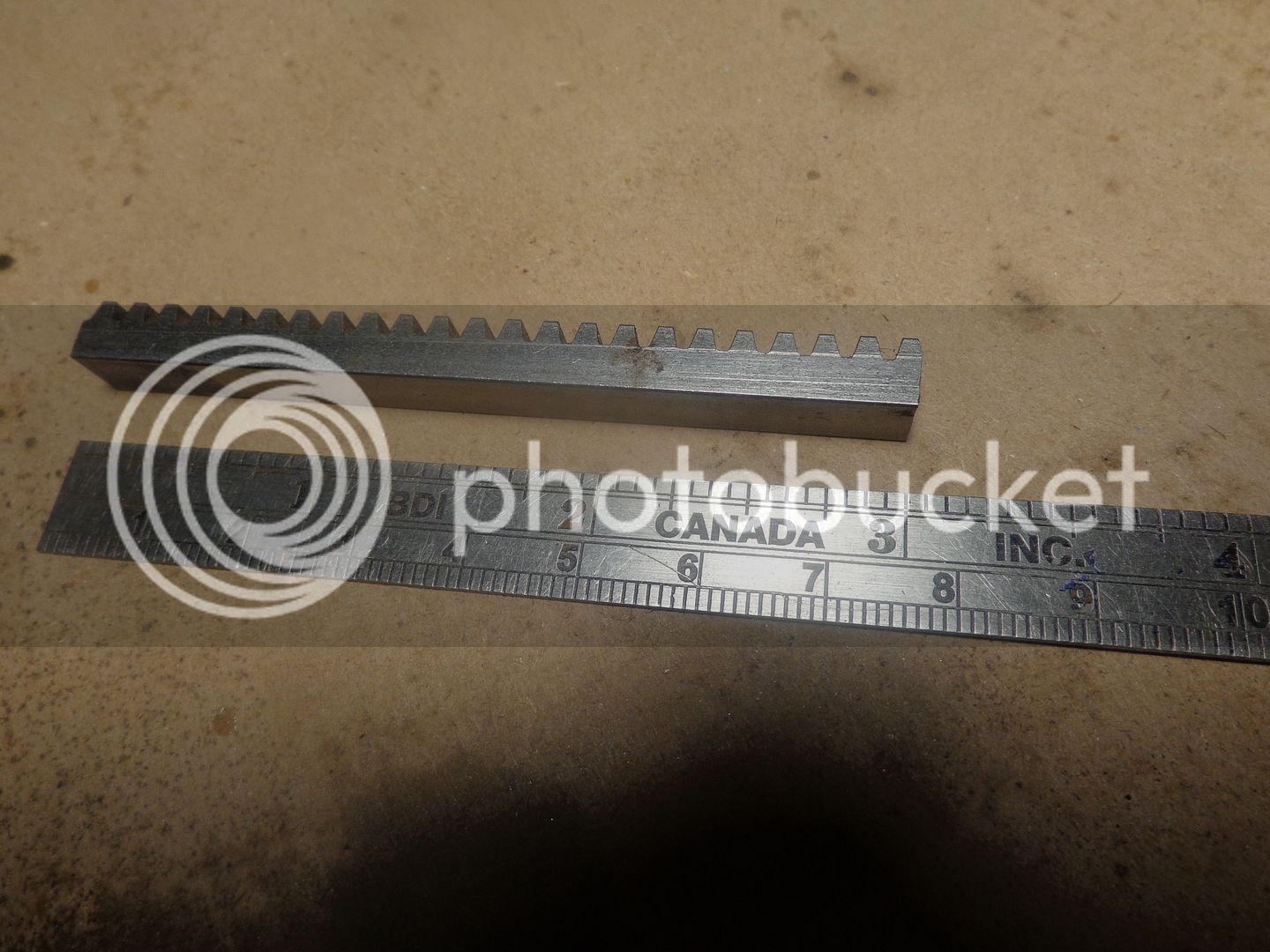
Maybe we're going to rethink this a little. I have a 3" length of 24 DP rack left over from my sawmill. The "wood" I want to split is only 1 1/2" to 2" long. I found a video on the internet that is so simple I think I will try to copy it.

[ame]https://www.youtube.com/watch?v=C4_Oze0-Cy4[/ame]
 
If you look at the diameter of the pinion in the video, it is much smaller in relationship to the rack than I am able to approach. The smallest gear I can cut is a 12 tooth, which has about a 1/2" pitch diameter. I will have to do some experimenting and see if this will drive the ram too fast or not. Although it would be less hassle if it doesn't, it's not a deal breaker because I can slip a gear reduction in between the flywheels and the pinion shaft. I have a set of 3 7/8" diameter x 1/2" thick steel flywheels that I have been saving for a project, and I think they would be just about perfect for this.
 
I saw one like the attached picture 35-40 years ago at an engine show somewhere in the New England/New York area. I have a ton of pictures, actually slides, stored away somewhere because I thought it would be a hoot to make a scale model of one...someday. This picture I grabbed from the world wide interweb.
If I recall correctly, and mind you that was a looong time ago, the wedge just cycled up and down and you shoved the wood in on the upstroke.

John

ANTIQUE LOG SPLITTER.jpg
 
Last edited:
Brian,
I think which ever way you go it would be important to use a mechanism to activate the stroke when you want and not rely on timing to get the log in there. Imagine doing a demo, maybe after a drink or two, misjudging the timing feeding the log, which would be more crucial on a model compared to a big full size machine. Then having to get rushed up to hospital to get your finger sewn back on. Simple is great, but Safety is better.
That would be one demo nobody forgets!
Paul
 
As a kid, I remember seeing the workers at the local wood yard using one of those continually moving wedge splitters. Just grabbing the short piece of log and placing it under the wedge at the right time. Never looked to see if they had all their fingers.

Paul.
 
Metalmuddler--I agree with you 100%. Although the thought of a fully automatic machine that cycles endlessly is enticing, it is just too risky, even as a toy. I have grown very attached to all these fingers and thumbs over the past 68 years-----Brian
 
The problem I see with that rack drive is that the rack is pulled down onto a spinning pinion. There is going to be some gear grinding when that engages, It will need to be pulled down quickly and not allowed to slip.

I still like the continuously moving wedge.
 
The problem I see with that rack drive is that the rack is pulled down onto a spinning pinion. There is going to be some gear grinding when that engages, It will need to be pulled down quickly and not allowed to slip.

I still like the continuously moving wedge.

Hi Ron
this type of splitter has been used for about 35 years I had one:wall:
the gear don't grind at all " surprisingly" but the biggest issue was
that the cutter was on the ram istead of this flat plate they are using now.
and if you didn't cut that peace of wood the first shot it would stuck in your lumber:fan: cause it's a spring return
 
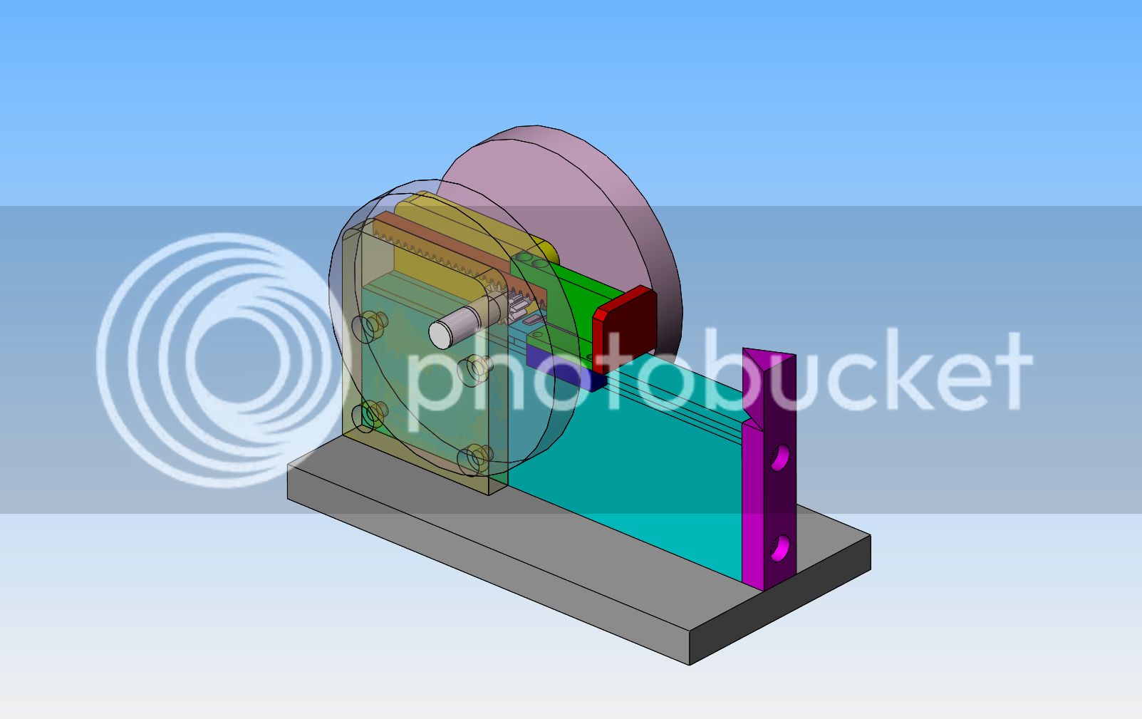
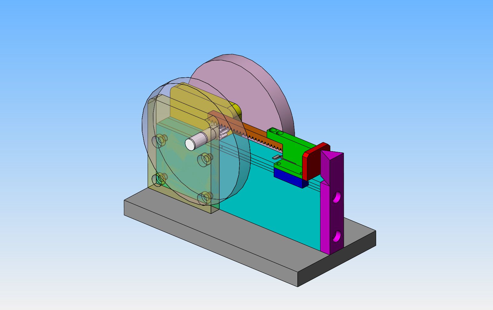
Here we have the new version in retracted and extended positions. I haven't designed the mechanism which holds down the rack in contact with the gear yet---I will do that this afternoon. those flywheels are 3 7/8" diameter. It will take a piece of wood 1.9" long.

 
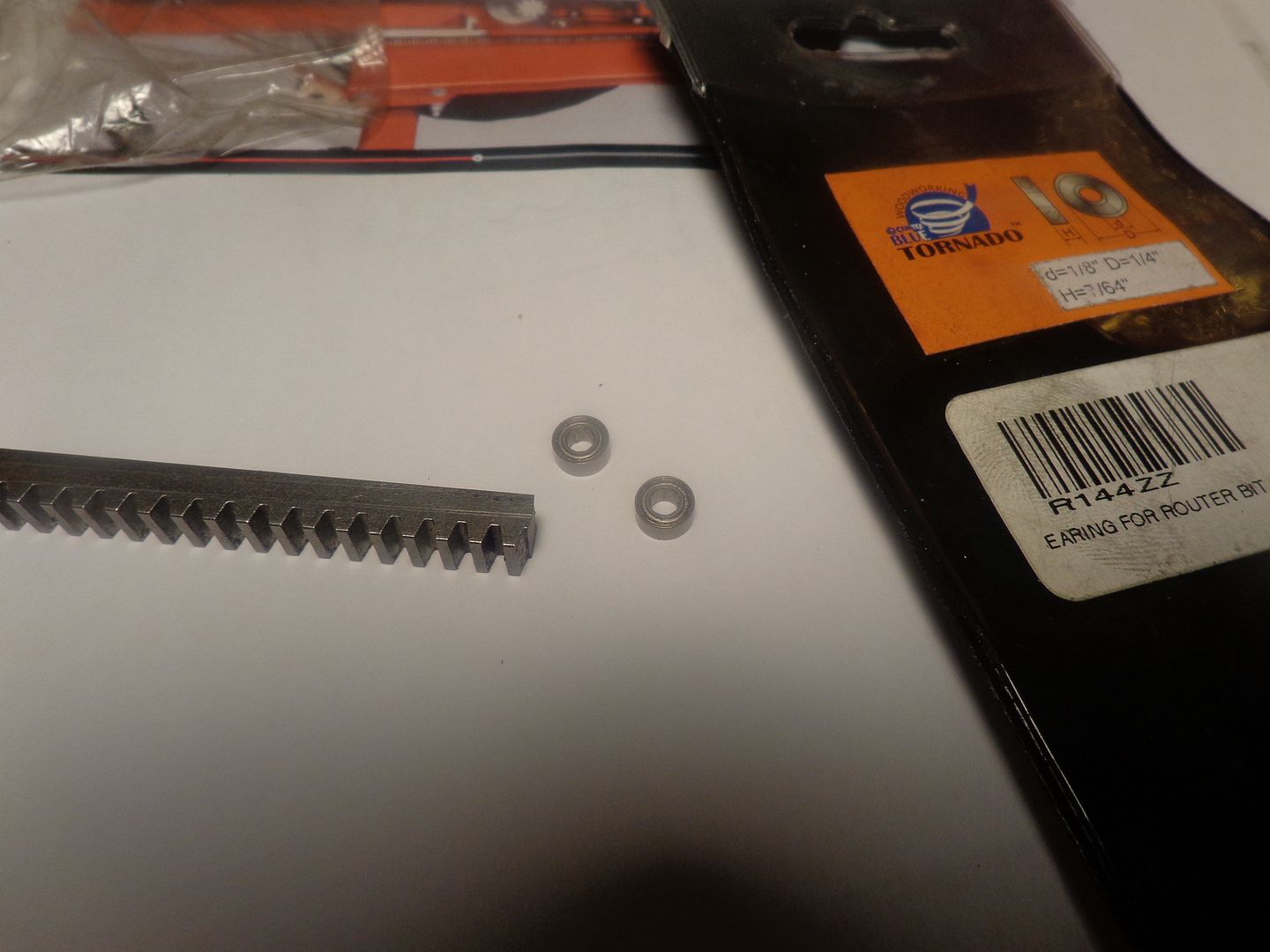
These will make perfect "hold down" bearings to ride against the back of the rack to keep it engaged with the pinion. They are router follower bearings. These are what I use for cam followers on some engines I build.
 

Latest posts

Back
Top