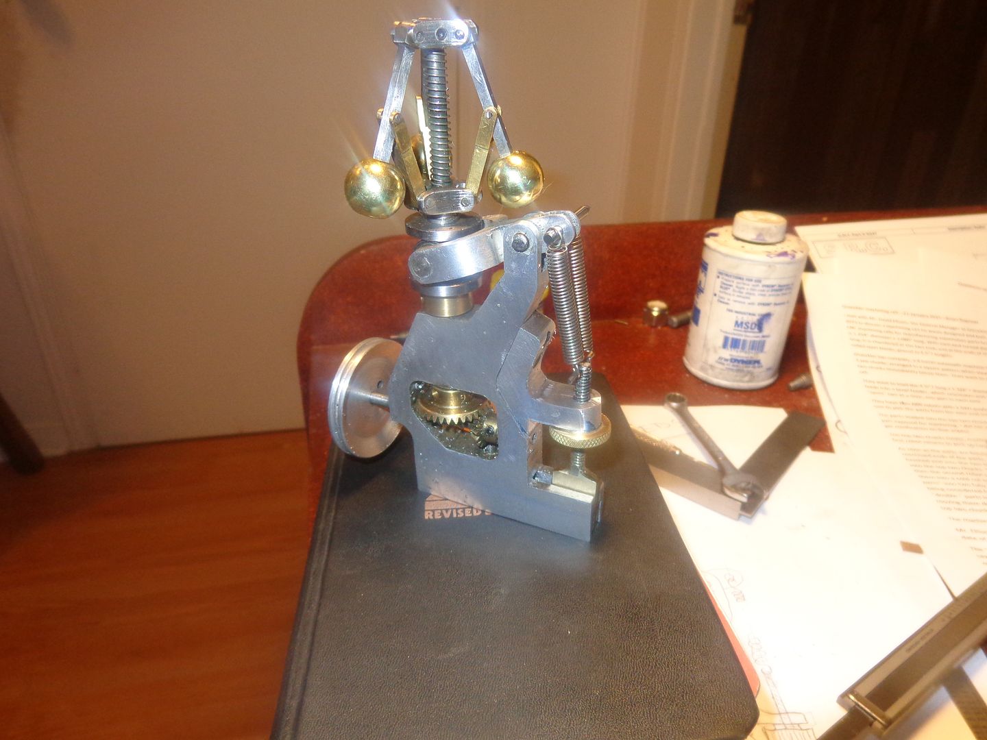
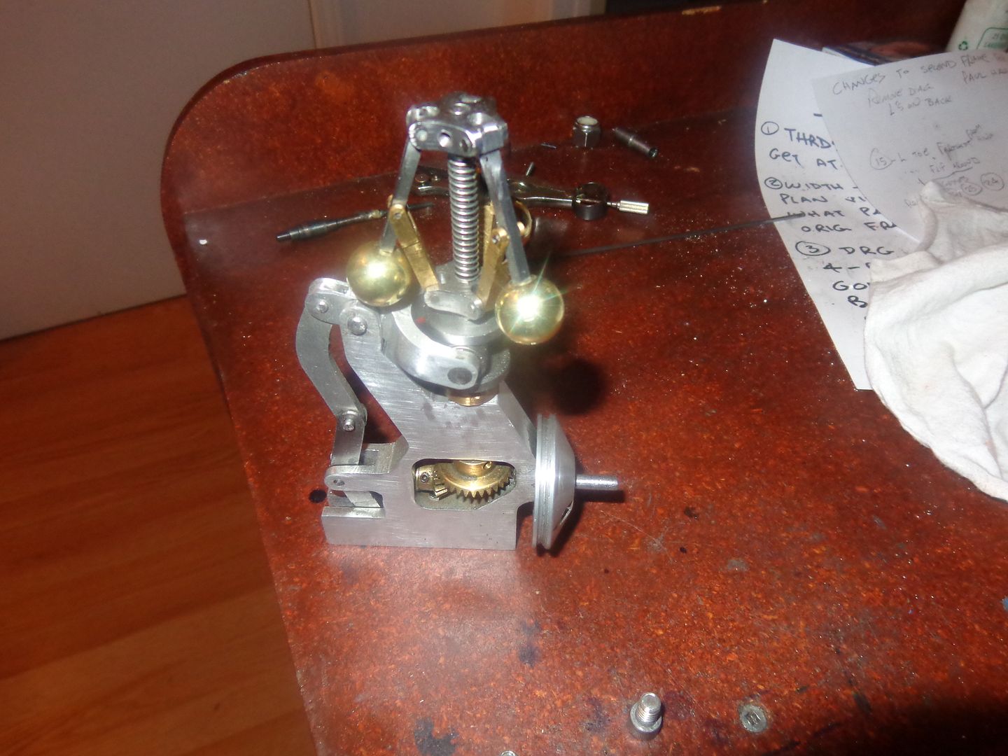
What's going on here?? Well, I'm at the prototyping stage of an adjustable counter spring for this governor--and what I have so far works. The governor in it's original form as seen in the very first post, had a couple of link arms that were redundant--not needed any more. Also, with no means of adjusting the compression spring riding on the center of the stempost, what you got was what you got in terms of when the mechanism activated at a certain rpm. Now in a perfect world, you want to be able to make this adjustment when the machine is actually running, and that is not possible--without the changes I have made. You will see that I have changed the shape of the governor body, removed the redundant links, and added a bracket to the body. A threaded rod passes through a plain hole in the new bracket, with a flat piece of brass soldered to the end of it, and the flat piece of brass fits into a slot in the aluminum body to keep it from rotating. A threaded and knurled "finger wheel" can be turned to move this threaded rod either up or down in the hole. The other end of the threaded rod is cross drilled for a .093" cross pin, and a pair of tension springs run from the cross pin up to the end of the yoke lever. By tightning the knurled finger wheel and forcing the threaded rod down, I can put more tension on the two tension springs. This tension serves to counteract the compression spring on the stempost. This can be done while the governor is actually being driven by whatever machine it is mounted on.---And, since I am effectively changing the force the compression spring exerts on the flyball mechanism, I can change the rpm at which the flyball mechanism activates. It works!!! I can feel the difference in force needed to lift up the governor arms when I tighten the adjuster and put more tension on the tension springs. I have a bit of work to do yet before I make an actual dynamic test, but this is very interesting. I still have no firm plans about mounting this on one of my i.c. engines, but the method for adjusting it does work. I will make a short video to demonstrate this "adjustability" tomorrow.