1:8 scale 3HP buffalo twin marine engine

Home Model Engine Machinist Forum

Help Support Home Model Engine Machinist Forum:

This site may earn a commission from merchant affiliate links, including eBay, Amazon, and others.
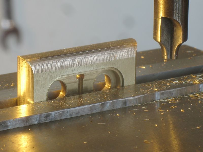
Further progress on the cylinder head the curved top required a new cutter


Some of the shaping to the top has been started with files, and the bottom plate is fitted to the water jacket.


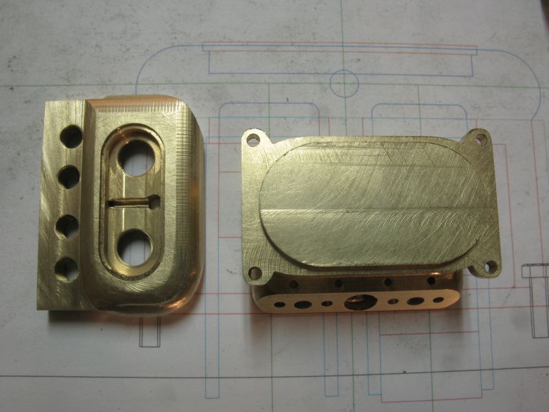
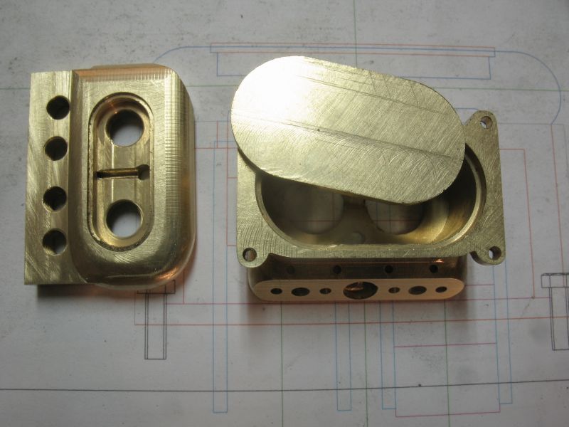
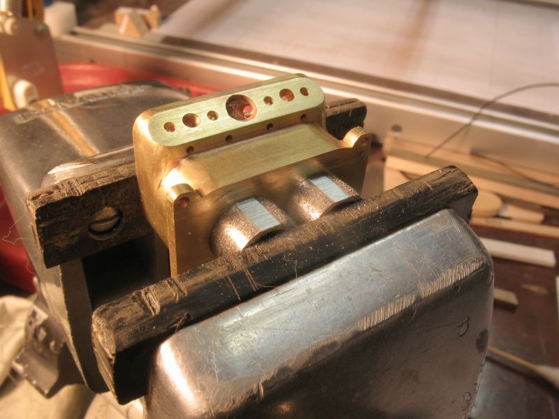
The liners are reamed and a press fit.


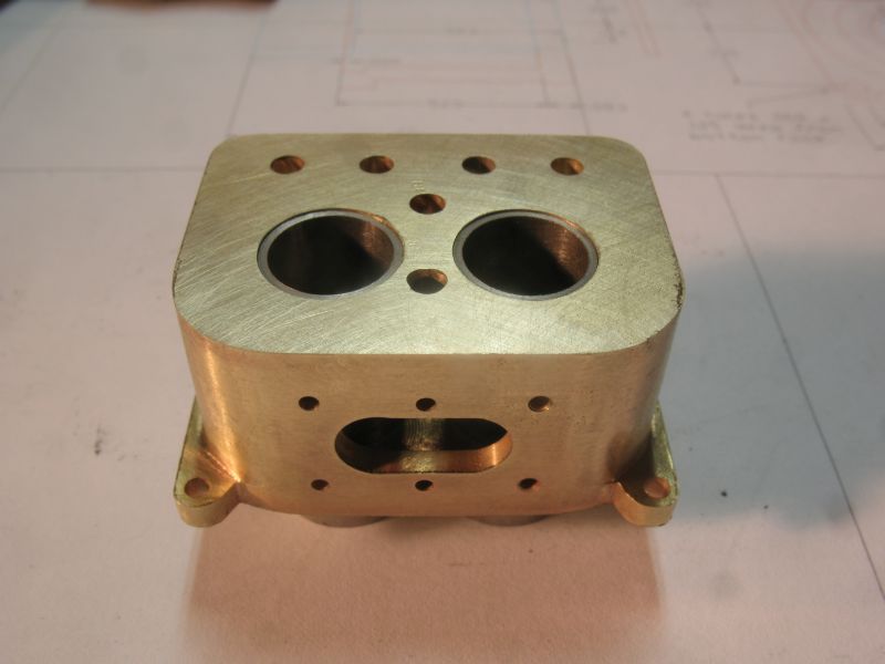
The bottom of the liners are flattened on both sides to ensure that they stay in place, they will slide fit into the top of the crankcase


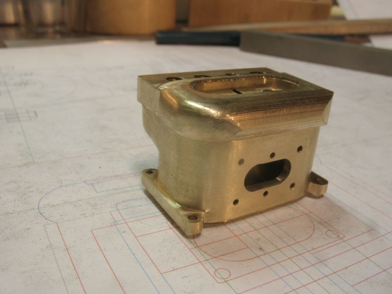
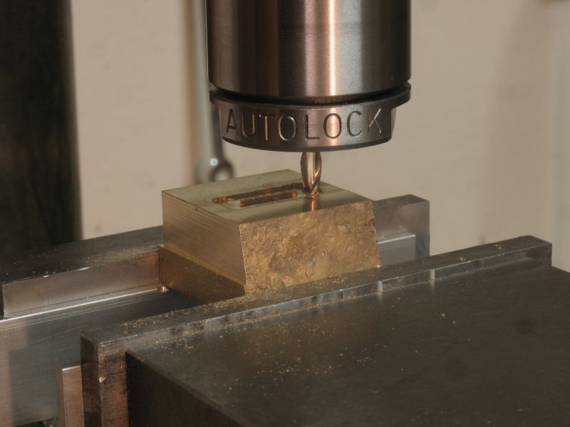
The start on the crankcase.


Michael
 
After doing a few experiments with the valve stem springs and keeper, I have increased the diameter of the valve-stem to .060" inches leaving the narrow section for the keeper at .046"

This was one of the early tests using the .046 stem the spring is .078 in diameter and the wire is .011. the keeper was a bit fiddly. I can safely increase the stem diameter and still maintain the .078 diameter springs the length of the springs are ..259" presently I am learning how to wind them so that there is a double coil at each end with the wider spaced turns in between. I have found that it is better to make them this way rather than winding a length then stretching it out to form the compression spring.


The crank case is progressing well at this time also. there is a fair bit of hand filing to finish up the corners because I do not have the requisite end mills to do all this work on the milling machine.


The next picture shows the flats on the sides of the liners slipped through the top of the upper part of the crankcase.


Michael
 
Some further progress on the crankcase I ended up making another cutter to make the recesses on the bolting flange.


This picture shows the recess right off the mill


The holes for the camshaft bearings and the back opening in the case.


Still need to finish filing the top part.


A close up of the new cutter, I needed a long reach and small diameter, the diameter is .086, it is a simple single face-cutter design easy to make out of drill rod.


Michael
 
further progress the oilpan and lower crankcase are a composite of a machined piece and some bent sheet.


machining away the areas that will be hollow


fitting the parts the central cross member is relieved to allow the oil to equalize.


test look at overall assembly


more


last one for now.


Michael
 
A milestone today I roughed in the main bearings.


I am taking some time deciding whether to fabricate the crankshaft or machine it from some bar.

Michael
 
Michael,
You are doing a marvelous job on this engine. Hard to believe the amount of progress you have made in only one month.
Gail in NM
 
Al and Gail thanks for your kind remarks, it means a lot from such accomplished modelers.
began work on the crankshaft, I decided to fabricate it from gauge-plate and drill rod


I test fitted the parts together and will get them accurately aligned before silver soldering the lot together then cut away the two parts of the main shaft between the con rod shafts.


Michael
 
Hi Michael,
Excellent work on your engine. It's always nice to see something unique being built . As I'm sure you have read on many other posts one of the most important things it to get the valves sealed well. This is one of the most critical processes in getting an engine to run well.
Keep up the good work.
gbritnell
 
George Thank you for your encouraging comment.
I silver soldered the crankshaft together today and it was a success as far as the soldering goes


I used a couple of pins with the diameters set to the spaces between the plates the silver solder was preplaced by bending some fine strips around the shafts on the outsides of the bearing areas


Cut out the parts not needed, and began to make the classic mistake of cutting out the wrong part on one of the cylinders so this crankshaft will have to become just a placeholder which I can use to fit and work the con rods and pistons. To say I was gutted would be an understatement because I had just finished saying to myself "don't cut away the wrong bits" I went ahead and finished cleaning it up so that I could use it for test fitting purposes knowing that i now have to make a second shaft.


I was pleased that it did not warp and when fitted into the bearings spun nicely between my fingers.


Next to work on the con rods and pistons.


Michael
 
I'm enjoying the progress on this interesting little engine. Sorry about the mishap on the crankshaft; I'm sure the new on will be just as nice or better than the first one.

Thanks for taking time to post your progress.
Dave
 
Thanks Dave, Glad you are enjoying the build.
I took a break from the crankshaft for a change of pace and built a couple of priming pots for the top of the cylinder head, these were really fiddly things to make but they will work, I used some tapered clock pins for the taper part of the body.


the tiny handles are silver soldered.


overall shot


This is quite small


I think that the next engine will be a little bigger.

Mike
 
Hi Mike,
I just found this thread and enjoyed reading it through. Nice work I will be reading your progress.

Dan
 
Hi Dan nice to have you along, Moshe thanks

I am working with some very small gears from an old Edison servomotor to build the reversing mechanism this first picture shows the small gears for scale and possible use.


The next picture shows the progress drawing incorporating the gears I have already resized the lengths of the pinions, today i am going to make the casing.


Michael
 
some further progress on the gearbox.


There is still a fair bit to do to get it all working smoothly on the engine it does work though with respect to the reverse so now the mounting will be sorted and the cone and lever mechanism.

Michael
 
I have been working and reworking the gearbox, I have made three of these now and the final one has some 48dp pinion wire for the gears getting the band clamp to work properly has also taken a fair bit of fiddling and filing.


This is version number 2 of the band clamp, the lever has one side angled to match the clamp so that as it rotates forward it releases the clamp. When it is finished the clutch will also engage at the rear of the gearbox causing the whole gearbox to rotate with the crank and prophaft locking the planetary gears inside.


The clutch is being made with the top of an allen head cap screw.


Also made a flywheel

Mike
 
Back
Top