Oilfield Engine (Was Bessemer...)

Home Model Engine Machinist Forum

Help Support Home Model Engine Machinist Forum:

This site may earn a commission from merchant affiliate links, including eBay, Amazon, and others.

cfellows

Well-Known Member
Project of the Month Winner
Joined
Aug 25, 2007
Messages
3,890
Reaction score
715
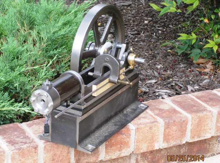
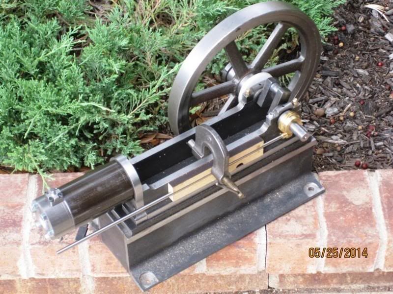
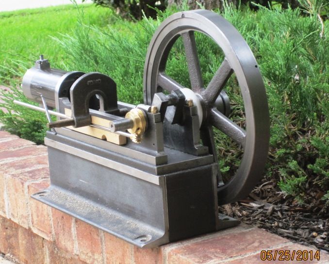
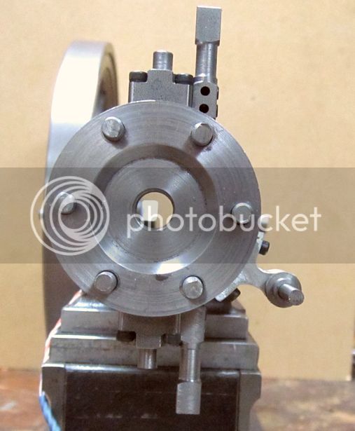
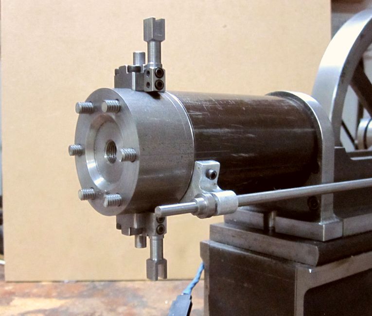
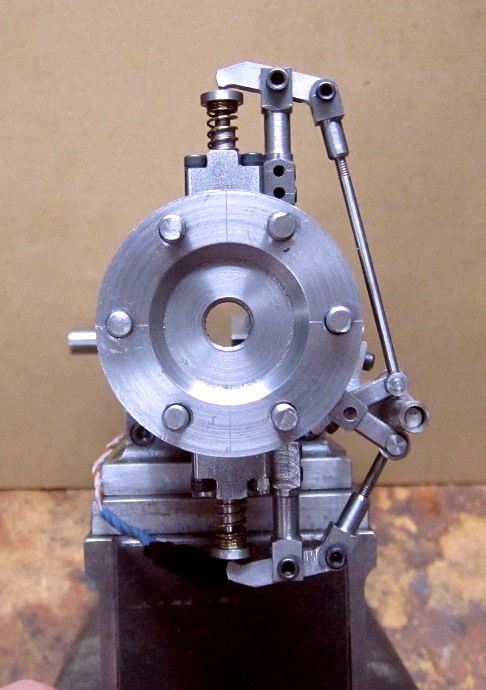
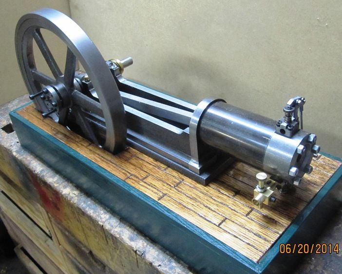
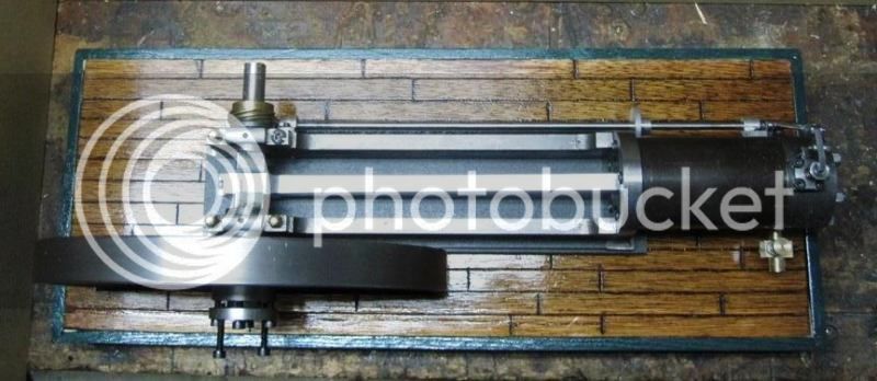
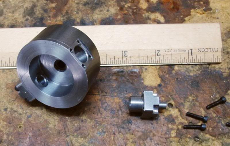
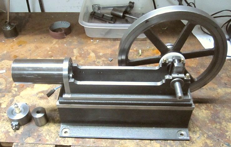
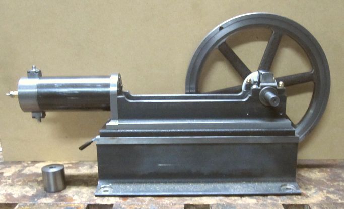
I'm back to work on my (used to be Bessemer) Oilfield engine. Since I'm converting it to 4 stroke operation, I guess it will just be a generic oilfield engine. I'm retaining the frame, flywheel and crankshaft, but the rest of it will be new. I want it to have a sideshaft operated cam and I've already made the helical gears required for it. Then I decided to move on to the head since that's a pretty tricky part of this type engine. I've been working on the design for over a week. Here is the outside with a glow plug screwed in and one valve cage attached. I plan to use spark ignition, but will need to order a plug for it.

IMG_3700_zps390d4d13.jpg


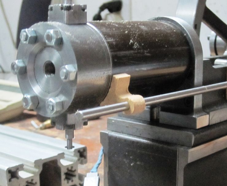
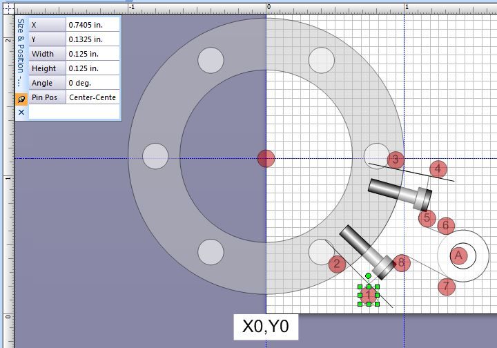
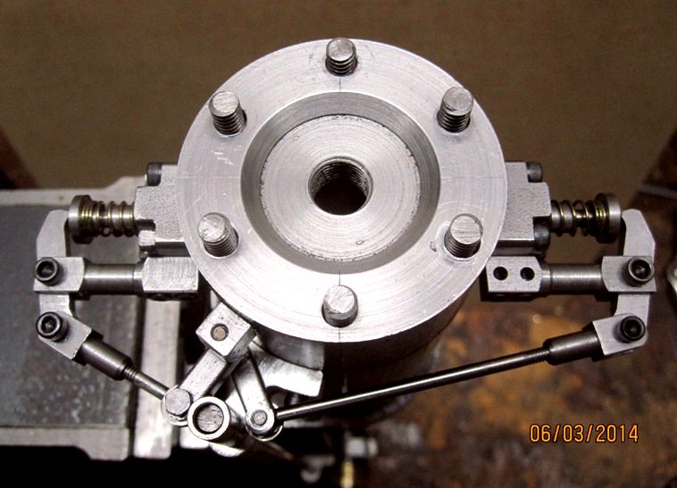
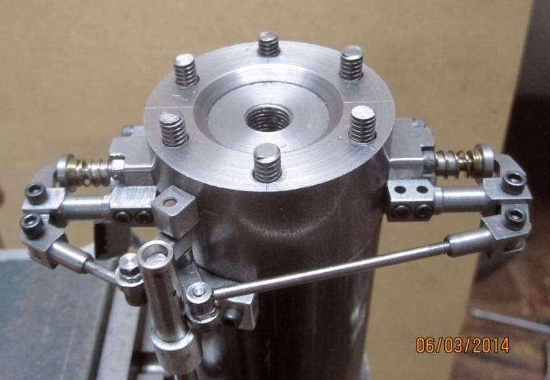
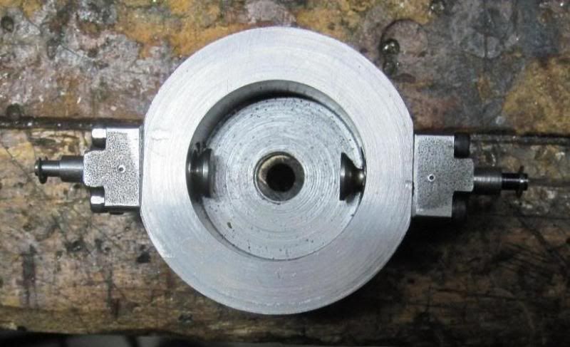
Hear is the inside, showing the combustion chamber, which is 1.25" diameter and 5/8" deep.

IMG_3701_zps3bce6dd7.jpg


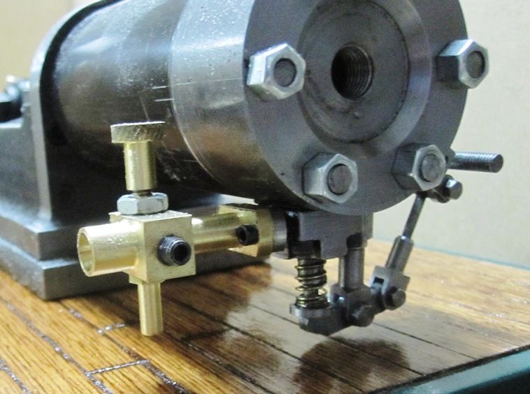
The exhaust valve will be on top and the intake will be on the bottom. The bore of the engine will be 1.25" and the stroke will remain at 1.75". The displacement will be 2.15 cu in (35 cc).

Chuck
 
I'll be watching Chuck. ----Brian

Hey, thanks for checking in, Brian.

Today I fitted the new cylinder to the frame today. It's made from a 4" length of 2" OD x 1.25" ID DOM steel tubing.

IMG_3703_zps6d12ce24.jpg


I will be shortening it from it's current 4" down to about 3", but first I want to make the new connecting rod and fit the piston. Here's a picture showing what the head and valve cages will look like.

IMG_3704_zpsf05d365a.jpg


I will also need to mill out a cavity and add a water jacket at some point.

Chuck
 
I wanted to get started on the connecting rod today, but, alas, I searched the shop high and low and couldn't find a piece of aluminum anywhere close to the size I needed. It'll have to wait until Monday when I can get down to Metals4U and see what they've got in their cut-off shelves.
In the meantime, I made the valves today. I fabricated them from 1/8" drill rod for the stems and silver soldered 3/8" steel ends which I turned smooth and cut the angled valve faces...

IMG_3705_zpsf29b297a.jpg


This is the tool I used to groove the ends of the valve stems for the e-clips...

IMG_3706_zps676ef936.jpg


That's one of 3 small slotting saws I bought for under $10 at Harbor Freight. It really worked very nice, turning the valve stem at around 120 RPM as I made the cut. The chips came off in nice, tight, small curls and the groove is about .025" wide.

Here is a drawing of the my current plan for the valves, rocker arms and push rods.

Capture_zpsb75c07e0.jpg


I still have to figure out the lifter arrangement. It'll probably be some kind of roller attached to a swing arm so it can roll on the cam.

Chuck
 
Yesterday I picked up a piece of 1" x 1/2" aluminum at my local metal supply store. I cut my rod to length (11") cut off the rod cap, then drilled it, tapped it, and re-attached it so I could bore the big end journal. I also measured and drilled the hole for the small end. Exactly 10" from center to center. This is going to be one heck of a long rod!

ConRod_zps96a35aa0.jpg


In the picture above, I'm showing the aluminum rod with holes bored and an MDF cutout of the rod profile that I plan to cut. The profile in the MDF was cut using a 5/16" end-mill in my CNC mill. I developed the G-Code myself using this drawing I made in Visio.

ConRodDrawing_zps38c86c62.jpg


Here is the G-Code

O0001 (Main Program)
(Tool starts at home position 0,0)
#100 = 0 (Variable to control Z Axis)
M98 P0002 L10 (Perform the cutting loop 10 times)
M02 (End of main program)

O0002 (Sub Program)
g01 x1.2813 y0.6875 f8 (Go to position 2, this is where the cut will be started)
#100 = [#100 + .052] (Increment the depth of the Z-Axis by .052 inches)
g01 z[#100] (Move the Z-Axis to the incremented depth)
g03 x1.5 y0.4688 i0.375 j0 f5 (Make a cutting move to position 3 with a counter clockwise arc, centered i, j offset from current)
g01 x10.4537 y0.3921 (Make cutting move to position 4)
g02 x10.4537 y-0.3921 i0.310 j-0.392 (Make a cutting move to position 5 with a clockwise arc, center i, j offset from current)
g01 x1.5004 y-0.4688 (Make cutting move to position 6)
g03 x1.2813 y-0.6875 i0 j-0.375 (Make a cutting move to position 7 with a counterclockwise arc, centered i, j from current)
g01 z0.010 (Lift the Z-Axis to 0.1 inche above the work)
m99 (End of Sub Program)

Heck, who needs CAM???

Chuck
 
Thanks for the comments, folks. Today was my 24th wedding anniversary, so I didn't get a lot of time in the shop... :(. But a good movie and nice dinner with the spouse made up for it.

I put together a fixture to hold the rod. I made it out of wood so I could mill past the bottom edge of the rod. I got it fastened to the milling table and managed to get about 60% done.

I'm being pretty conservative, making full width, .040" deep cuts on each pass, so it's taken me 8 passes to get this far, about an hour of milling time. I have 5 more passes to go, so I should finish it up tomorrow.
Photobucket is down for maintenance so I'm attaching today's (not very good) photos.

IMG_3712.JPG


IMG_3713.jpg
 
I finished up the connecting rod today. Cosmetically, it turned out very nice. However, I think it's a bit beefy and I'll probably reduce it in cross sectional thickness and perhaps height.

IMG_3714_zps3e75daf2.jpg


IMG_3718_zpsc32a874f.jpg


I've noticed a disturbing inaccuracy in my CNC converted mill drill lately. I tested it today, finding that an MDI command to move the X-Axis 10" only moved it about 9.875, measuring with a ruler. I had originally thought the ball screws were 5 turns per inch or a lead of 0.2". Turns out, the lead is really 5mm, which is only 0.19685". I changed the configuration in Mach3 from 30,000 steps per inch to 30,480 steps per inch and now it is dead on.

Chuck
 
I had a fun day in the shop today. I did my first ever thread milling. I wrote the G-Code for it which was really easy. I also used my right angle milling attachment and my 4th Axis...

IMG_3725_zps70034986.jpg


The milling cutter is a 60 degree included angle cutter. I'm making the studs that hold the head on from 3/16" drill rod, threaded 10-24.

IMG_3719_zps00471bb5.jpg


Here's a finished stud, best threads I've ever cut!

IMG_3721_zps8376ef48.jpg


Here's some pictures of the engine with the head attached. The nuts were cut from threaded rod coupling nuts...

IMG_3723_zpsdaf3e31d.jpg


I've also got the side shaft temporarily sitting in place with the helical gears.

IMG_3722_zps9e69593a.jpg


IMG_3724_zpse22ff5fd.jpg


The side shaft in the picture is 3/16" diameter, but I think I'll increase it to 1/4" since it is so long...

Here's a video of the thread milling process...

[ame]https://www.youtube.com/watch?v=6HO0DICwnSk[/ame]

I'm really pleased with how easy the thread milling was and how nice the results are. I've always been somewhat challenged in trying to do single point thread cutting on the lathe, so I think this method will be a nice alternative.
Chuck
 
Nice work chuck.--But--You are getting to the point where you have too many toys!! I'm not going to be able to keep up to you.---Brian
 
Nice work chuck.--But--You are getting to the point where you have too many toys!! I'm not going to be able to keep up to you.---Brian

Thanks, Brian, I don't think you need to worry about keeping up with me, you seem to have the energy of a 10 year old!

I spent a lot of time today breaking new ground and experimenting with CNC. Here's the result... a prototype of the front side-shaft bracket cut from MDF.

IMG_3729_zpsbfb83550.jpg


I thought it might be interesting to see how I developed the G-Code for this bracket. First, I drew the design using Visio.

VisioBracketDrawing_zpsa28f9213.jpg


Then, I drew in the small, red, numbered circles at the different x,y points where a new g-code command would be required. The number represent the order of the points visited by the cutting tool. The circles are 1/8" diameter, which is the diameter of end mill used to cut the part. In the drawing, you can see that circle number 1 is highlighted. In the upper left corner, you can see where Visio displays the X,Y coordinate of the center of the highlighted feature, in this case circle #1. By moving the cursor from circle to circle, it becomes an easy task to code the g-code commands for each point. The only additional consideration is where the cutter has to travel in an arc. All you have to do is use an arc move command and additionally specify the coordinates of the center of the ARC. All this code is placed in a subroutine which is looped through n times, dropping the cutter a bit on each loop until the part is cut out.

Chuck
 
Progress has been a bit slow this past week. These side shaft engine designs are a lot more complicated when it comes to the valve actuating assemblies, cams, etc. And, since I'm making this up as I go along, it requires a bit more thought in getting everything to work right. I've now nearly finished and fitted the rocker arm support posts, which are made from 1/4" square steel rod...

IMG_3736_zps619f6358.jpg


IMG_3733_zps0f5b3a6b.jpg


And here are the lifter arms, made from 3/16" square steel rod.

IMG_3738_zps324f61eb.jpg


The solid end will pivot on a post which screws into the head and the slotted end will carry a small roller, 1/4" diameter, which rolls on the cam. Next I have to make the post and fit it to the head.

Chuck
 
Another day working on fiddly bits. I'm in the middle of doing the valve assemblies and today I worked on the exhaust lifter, roller, and push rod.

IMG_3739_zpsc5682f0d.jpg


The lifter bar is 3/16" square steel rod about half an inch long. The push rod is 3/32" drill rod and the screw that holds it all together is 3-48. The roller is made from 1/4" drill rod. The pushrod end is 3/16" cold rolled steel, drilled and tapped 3-48 to accept the push rod.

Tomorrow I'll work on the intake assembly.

Chuck
 
Thanks, Brian. I haven't been on the forum much in the past 24 hours and need to catch up.

I've got the valve assembly, rocker arms, push rods, lifters and cam rollers pretty well done.

IMG_3744_zpsdffd0a66.jpg


IMG_3743_zps9b5caef6.jpg


IMG_3742_zps01b4d262.jpg


IMG_3740_zps983c18ae.jpg


This whole assembly was the hardest to design and the most worrisome about how it would turn out, not to mention making these little pieces and getting them to look decent. I'm pleased with the results and with a little fine tuning and some proper fasteners (the socket head cap screws in the rocker arms are temporary), it's going to work just fine.

Chuck
 
Thanks, Brian, almost looks like a kinetic sculpture, doesn't it?

Chuck
 
Chuck,
Great work. Really neat design. You had me wondering where you were going with it.
I got into a lot of trouble with the arrangement on my Wyvern just because my skew gears were different than the drawings called for, as it relocated the side shaft a tad. I was already over my head just with the cylinder head design.

GUS
 
I've been plugging away slowly on this project. I spent some time getting the valves sealed and making some gaskets for the valve cages. The past few days, I made a new base for it. I never really liked the metal base I had made, so I made a platform style base out of wood. Almost looks more like a factory type engine now.

IMG_3853_zpse8579d0e.jpg


IMG_3856_zps0434a152.jpg


IMG_3855_zps18e0775c.jpg


I made the top from a piece of half inch Birch plywood. The faux planks were made by using a scratch awl to create the planks and joints. Then I applied a walnut stain and wiped away the excess pretty quickly. The stain quickly soaked into the scratches but wiped off the surface leaving a nice contrast. Then I applied a couple of coats of high gloss urethane. The sides of the base are made from plain pine and painted Hunter green.

I also built and installed the carburetor.

IMG_3854_zpsde8c9bde.jpg


I have had it running briefly with a glow plug, but I need to complete the hall sensor installation, then the fuel tank. I also need to complete the water jacket, but that can be done later.

Chuck
 
Thanks, Don, Bill.

I've been thinking for a while now where and how to mount the hall sensor. I finally decided on a design and spent today getting it installed.

IMG_3857_zps551a7ac8.jpg


IMG_3858_zps51b6c7c7.jpg


IMG_3859_zps53da9b89.jpg


The wire goes down through a hole into the base then out the front through another hole. The battery and ignition module will be separate from the engine. I'm also making new intake and exhaust cams to provide a longer dwell on the lift. The previous cams weren't holding the valves open long enough.

Chuck
 

Latest posts

Back
Top