- Joined
- Aug 25, 2007
- Messages
- 3,890
- Reaction score
- 715
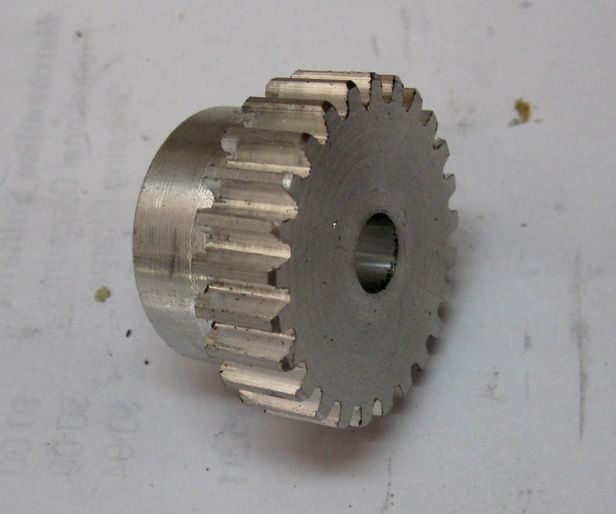
This is kind of a general interest post. I was real happy with my success in the shop today, venturing further into CNC, Mach3, and programming in G-Code, so I wanted to share it with anyone who might be interested.
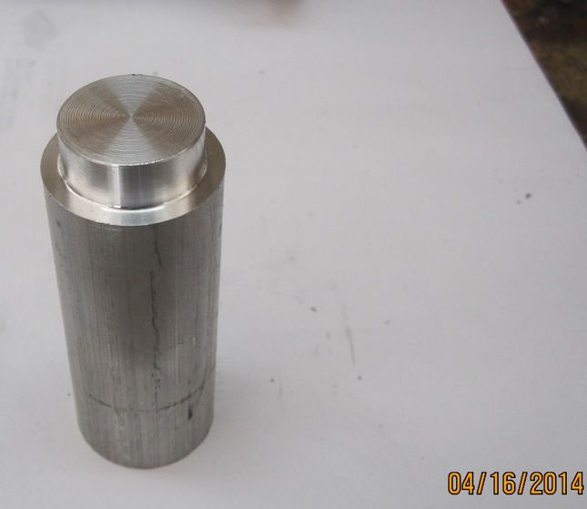
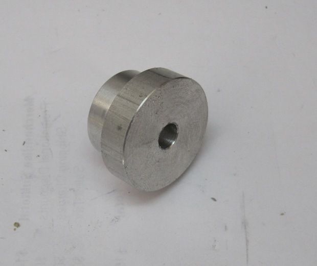
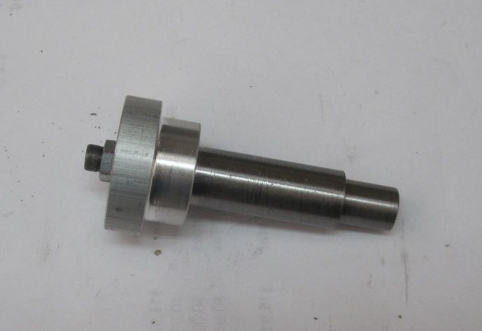
About a year ago, I built this electronic dividing head, using an Arduino micro controller and software I wrote to control it.
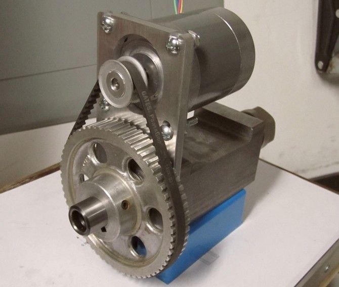
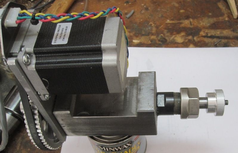
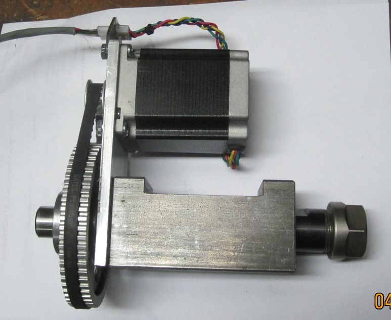
It was my first foray into stepper motors and the Arduino. Some months ago I had bought a newer, more powerful stepper motor and yesterday I finally got around to upgrading the dividing head with the new stepper. Here's some pictures with the new motor installed.
The motor replacement was easy since both the old and new motor were NEMA 23. However, the motor is double the torque of the old one. I ran into problems almost immediately with the electronics. The stepper controller I used originally couldn't handle the current of the new motor. So, I was faced with replacing it. Also, the 12v rechargeable battery I had been using was no longer holding a charge very long and, at any rate, a battery is not the ideal power source for a dividing head... running out of juice in the middle of a job would not be good.
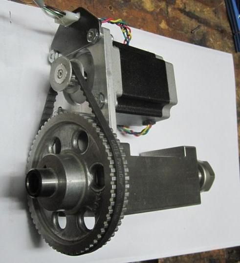
I had converted my mill/drill to CNC a few months ago and the stepper controller I used was a Gecko G540. It has a 4th axis output and is powered by a nice 24v, 15 amp power supply, so I put a new connector on the stepper motor and hooked it up to the Gecko. I powered it on and it worked fine.
I'm still a rank amateur with CNC, Mach3 and G-Code. However, I have written software most of my adult life so, after an afternoon of reading and a few hours of fooling around with code, I wrote the following G-Code for Mach3. Text inside the parentheses are comments. Commands for the 4th axis use the letter A and the number that follows it is the absolute position, in this case the number of turns, to rotate the work. So, for example, A1 tells Mach3 to rotate the work to 1 full revolution from the home position. A .3333 will rotate the work 1/3 of a turn from the home position. Note that I'm using absolute positioning, not relative. This means that each command tells Mach3 where you want the work to be positioned, not how far to move it.
%
O0001 (MAIN PROGRAM)
#100 = 36 (#100 is a variable name and is set to the number of divisions I want)
#101 = 1 (#101 is the variable which starts at 1 and gets incremented for each division)
A0 (This line commands Mach3 to move the 4th axis (A) to the 'Home' (0) position)
M98 P0002 L#100 (This command calls subprogram P0002. It loops the number of times specified in variable #100)
M02 (This command halts the program)
O0002 (Subprogram called by the M98 loop command in the main program)
M00 (This command pauses the program which I manually machine a gear tooth. Clicking 'Cycle Start' resumes the program)
#33 = [#101 / #100] (This calculation sets variable #33 to the position of the next tooth, which is tooth number divided by number of teeth)
A [#33] (This command tells Mach3 to rotate the 4th axis to the position in variable #33)
# 101 = [#101 + 1] (Increment variable #101 to the next tooth number)
M99 (Subroutine end, return to main program)
%
Works like a charm. And, I now feel like this new 4th Axis has a lot of possibilities.
Chuck
About a year ago, I built this electronic dividing head, using an Arduino micro controller and software I wrote to control it.
It was my first foray into stepper motors and the Arduino. Some months ago I had bought a newer, more powerful stepper motor and yesterday I finally got around to upgrading the dividing head with the new stepper. Here's some pictures with the new motor installed.
The motor replacement was easy since both the old and new motor were NEMA 23. However, the motor is double the torque of the old one. I ran into problems almost immediately with the electronics. The stepper controller I used originally couldn't handle the current of the new motor. So, I was faced with replacing it. Also, the 12v rechargeable battery I had been using was no longer holding a charge very long and, at any rate, a battery is not the ideal power source for a dividing head... running out of juice in the middle of a job would not be good.
I had converted my mill/drill to CNC a few months ago and the stepper controller I used was a Gecko G540. It has a 4th axis output and is powered by a nice 24v, 15 amp power supply, so I put a new connector on the stepper motor and hooked it up to the Gecko. I powered it on and it worked fine.
I'm still a rank amateur with CNC, Mach3 and G-Code. However, I have written software most of my adult life so, after an afternoon of reading and a few hours of fooling around with code, I wrote the following G-Code for Mach3. Text inside the parentheses are comments. Commands for the 4th axis use the letter A and the number that follows it is the absolute position, in this case the number of turns, to rotate the work. So, for example, A1 tells Mach3 to rotate the work to 1 full revolution from the home position. A .3333 will rotate the work 1/3 of a turn from the home position. Note that I'm using absolute positioning, not relative. This means that each command tells Mach3 where you want the work to be positioned, not how far to move it.
%
O0001 (MAIN PROGRAM)
#100 = 36 (#100 is a variable name and is set to the number of divisions I want)
#101 = 1 (#101 is the variable which starts at 1 and gets incremented for each division)
A0 (This line commands Mach3 to move the 4th axis (A) to the 'Home' (0) position)
M98 P0002 L#100 (This command calls subprogram P0002. It loops the number of times specified in variable #100)
M02 (This command halts the program)
O0002 (Subprogram called by the M98 loop command in the main program)
M00 (This command pauses the program which I manually machine a gear tooth. Clicking 'Cycle Start' resumes the program)
#33 = [#101 / #100] (This calculation sets variable #33 to the position of the next tooth, which is tooth number divided by number of teeth)
A [#33] (This command tells Mach3 to rotate the 4th axis to the position in variable #33)
# 101 = [#101 + 1] (Increment variable #101 to the next tooth number)
M99 (Subroutine end, return to main program)
%
Works like a charm. And, I now feel like this new 4th Axis has a lot of possibilities.
Chuck