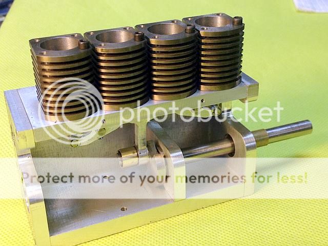
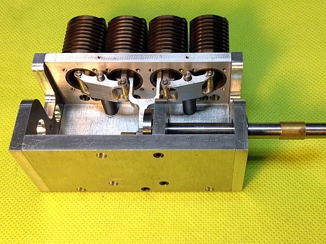
I finished up the parts for the other two cylinders and assembled the linkages on the second side. Every thing still works smoothly. Now with all the unknown areas addressed I can move on to making real parts. Most everything now is standard engine stuff. Of course it still takes time to make them.
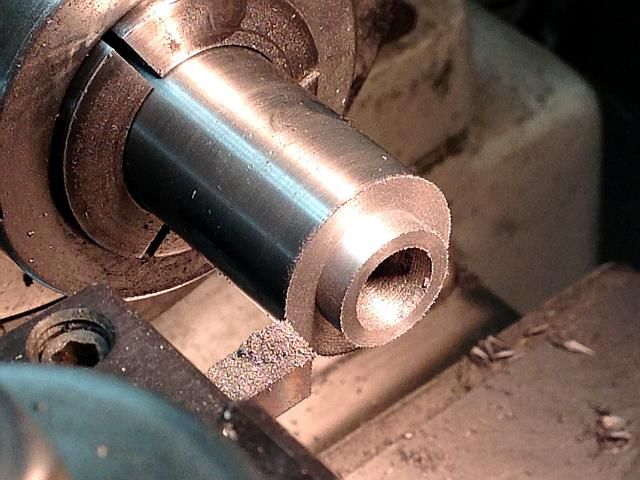
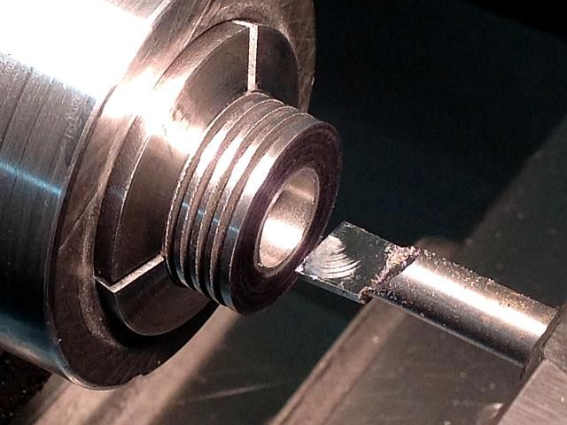
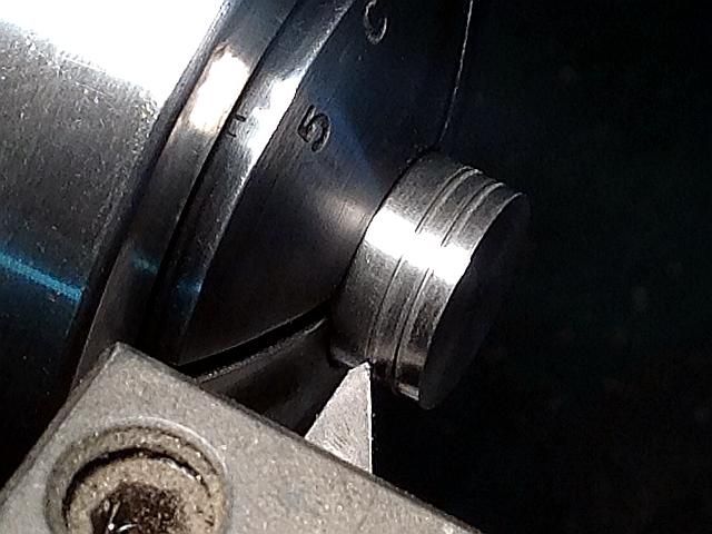
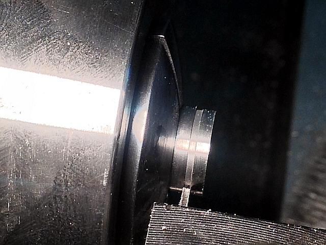
To start with this phase I started on the cylinders. The cylinders are class 40 cast iron. Started them off by drilling the bore undersize and then turning the spigot that goes into the top deck.
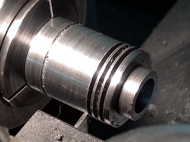
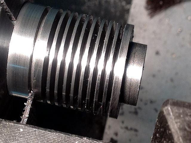
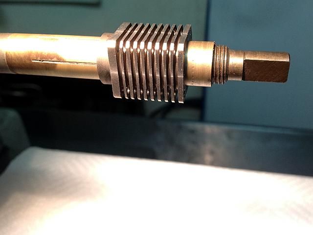
Then the fun part of machining the fins. Not hard but very repetitive. All the grooves were cut with a standard P-4 cutoff blade. The fins and the spaces between the fins are both 0.040 inch wide with the top and bottom fin wider for extra strength.
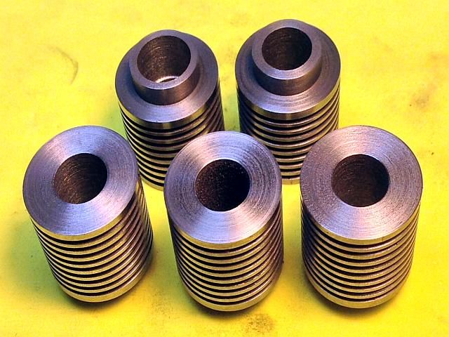
I made an extra cylinder because I messed up the fin spacing on one of them. It is close enough to be usable but would not look quite right with the cylinders so close to each other when installed.
Next up is to bore the cylinders to a 0.4988/.4900 target dimension. As a finishing step the cylinders will be lapped to a 0.5000 target dimension. But, before lapping all the external work will be done. This is because there will be a small amount of distortion when the outside features are machined and the lapping will take that out.
Gail in NM
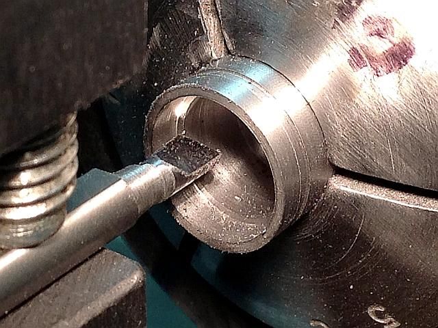
The cylinders are bored using a carbide boring bar. First all the cylinders were bored to 0.496 so I would have a uniform amount to of material to remove for the final boring operation and could do the final boring operation on all the cylinders with out having to change the cross slide setting. After the preliminary boring it was time to fix dinner in the oven so I put all the cylinders in the oven with the beans at 350 degrees F. When the beans were done I increased the temperature to 450 degrees while I ate dinner and then turned the oven off after dinner and called it a night. This is to reduce residual stresses in the cast iron. It is not really necessary and I some times do it and sometimes don't. Probably does not make much difference if the iron is of a good grade but it gave me a good reason to call it a night in the shop.
The cylinders were then final bored today. All of them were done without changing the cross slide setting between them. Next up will be the external machining of the flats on 3 sides and drilling the mounting holes. Then on to lapping.
Gail in NM
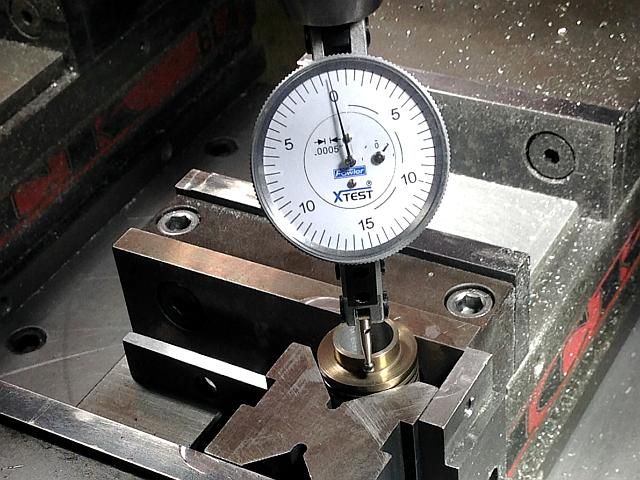
The cylinders as they are bored now are about 0.001 +/- 0.0001 from the finished size. I will detail the finishing operations next week after I finish the external features. The cylinders will have a lapped finish and the pistons will also be lapped, but separately. No rings will be used so a much finer finish is used than would be used with rings. The pistons will typically be lapped to 0.0002 under the cylinders for a running fit. I have been using this technique on the last dozen or so engines. This engine is a little bit different in that it has a 1/2 bore where the others have had a 3/8 inch bore. On my larger engines of previous years I left the bore with more texture to seat the rings.
Gail in NM
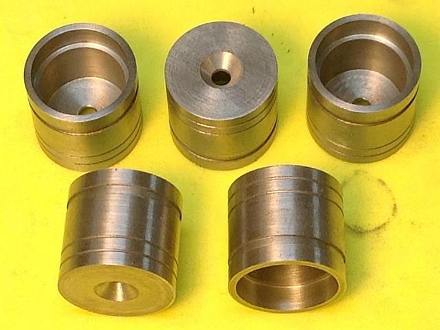
The external work on the cylinders is complete.
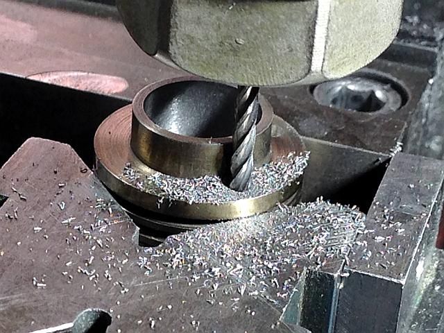
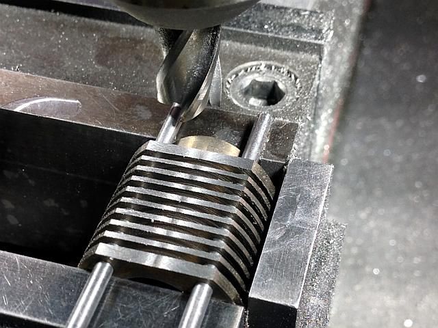
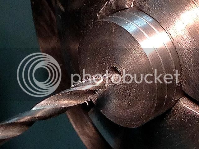
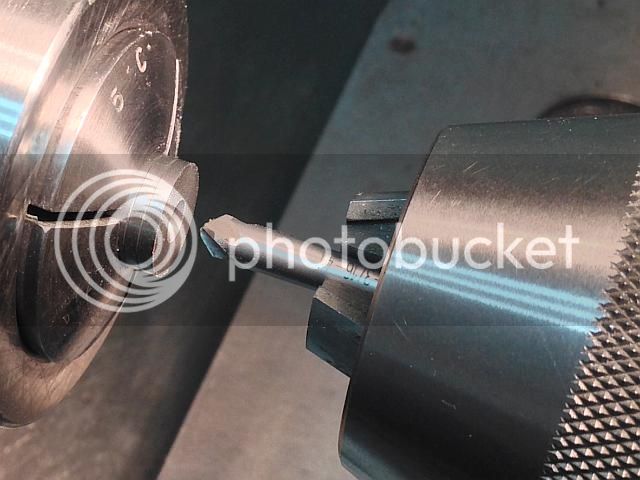
Started by indicating the cylinder in the mill vice with a vee block to hold it and a parallel underneath it to give the drill a place to go. This parallel placed so the drill bit will not hit it.
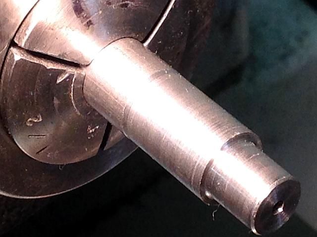
The cylinder is placed with the locating spigot up as the holes on that end have to match the tapped holes in the cylinder mounting plate. This makes sure that the holes at that end are located correctly. Cast iron bar stock is slightly softer towards the center and long drilled holes that are not on center line tend to drift towards the center. To reduce this I started the holes with a extra long end mill that would reach almost halfway through.
Then followed with a sharp drill bit to finish the holes to the other side. The milled hole was the same size the drill so it formed a good drill guide.
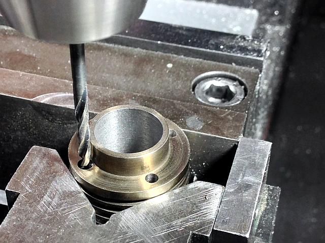
The sides were milled off on three sides. Rods were run through the two of the drilled holes at a time and rested on the vice jaws to index the cylinder.
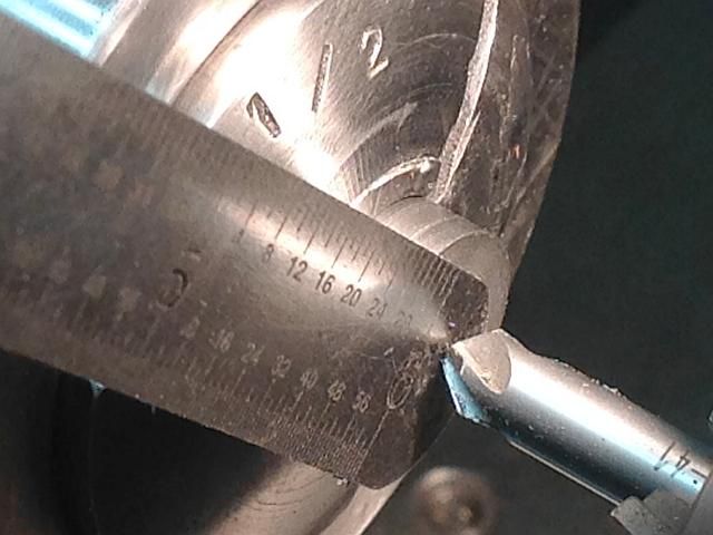
And finally the hole for the cylinder lubrication was drilled using a 1/16 end mill. An end mill was used as it raises less burr on the exit side of the hole so it is easier to remove with the lap.
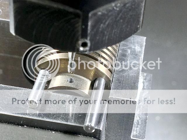
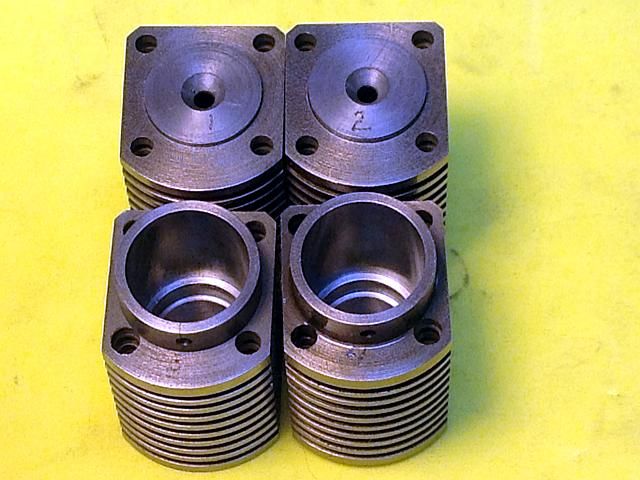
I had to stack the parts up to see what it is looking like so here are a couple of photos. The cylinder mounting plate has to come off so I can drill the mounts for the cylinder oilers. Still have to draw up the oilers but they are just going to oil cups.
Gail in NM
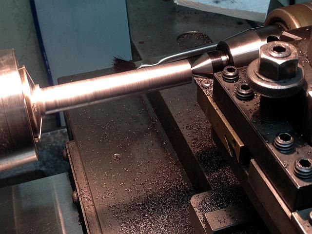
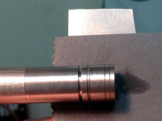
To finish up the cylinders the bore needs to be finished to size and be parallel and smooth. I had left about 0.001 inch for these operations when I bored them. I started with a Flex-Hone to knock off the tops of the ridges left by boring. This took out about half of my finishing allowance and left some cross hatch pattern in the bore. Some of this pattern will remain after lapping and is good for oil retaining. As this engine will not have a continuous oil supply while running this is important. I used a 280 grit Flex-Hone and only one full length pass in and out at about 500 RPM with lots of light oil. Of course the lathe bed was covered with paper towels during this operation.
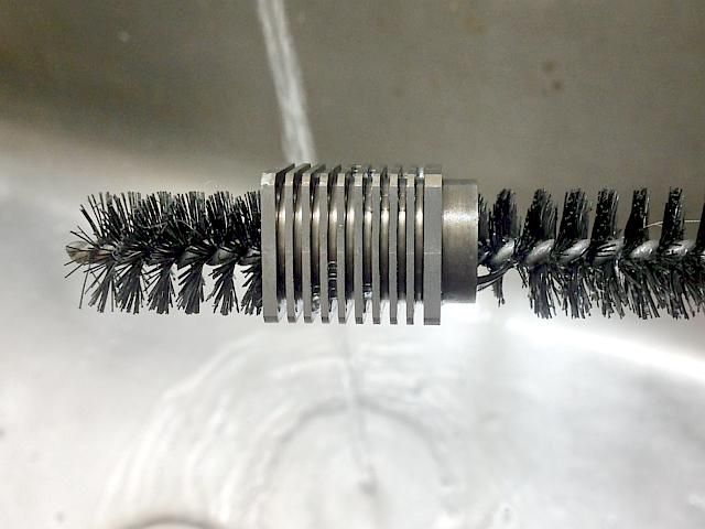
Then the cylinders were cleaned very well to remove any abrasive that might be left over.
Why do I show a photo of cleaning with a brush? Only to emphasize the importance of cleaning after every abrasive operation. Here I used a test tube brush with dish washing detergent and then rinsed off afterwards. If a plug gauge is ever used this is very important as the hard plug gauge will embed any loose abrasive in the bore for ever.
Gail in NM
It should be noted that Flex_Hones do nothing other than improve the surface finish of a bore. They will not correct any out of round or parallel conditions. I use them just to reduce the time required to lap a bore. Lapping can be done with out using them but it takes longer to get the same results.
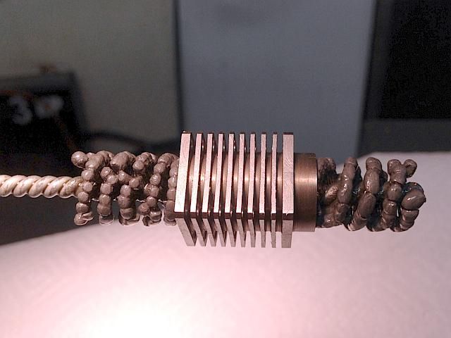
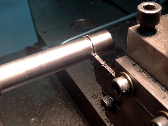
For the final lapping I use an adjustable Acro lap. They are inexpensive enough to hardly make it worth while to make my own in small sizes such as this.l I use diamond lapping compound. In this case I only used a single grit. It is 8 to 12 micron or approximately 1500 mesh. If I had not preconditioned the bore with the Flex-Hone I would have roughed out the bore with 20 to 36 micron first then changed laps and finished with the 8-12 micron.
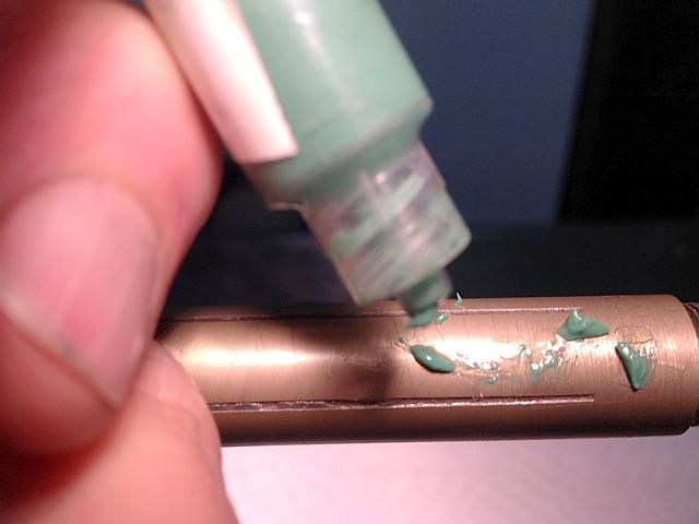
On a new lap I would have first charged the lap with compound by rolling the lap on a hardened surface with compound on it. Here I am using a well used lap so I just added a little fresh compound to the lap along with a liberal amount of light oil. In the second following photo you can see a drop of oil just forming on the bottom of the lap. It does not take much compound. I am using a 5 gram syringe that I have been using for at least 15 years and it is still over 1/2 full. If you are going to buy diamond compound shop around carefully. Medium load 5 gram syringe prices vary from about US$6 to US$25. The amount of compound I put on the lap is enough for all four cylinders.
The lap is adjusted so there is a comfortable pressure using a thumb-forefinger grasp on the part. The part is slid along the lap from one end to the other. There will be a slight bulge in the lap from the adjustment and you can feel as this enters the bore and exits. Goal is for there to be a uniform cutting pressure along the entire bore. I did all 4 cylinders at one setting and then expanded the lap and repeated, again with all 4 cylinders. This was so the cylinders all came out to the same size. My target was 0.5000 but I ended up with 2 measuring 0.5002 and 2 measuring 0.5003 inch. Since the pistons will be lapped to about 0.0002 undersize of the bore they will be close enough that they can be interchanged if they get mixed up. Of course this is not necessary but it's just the way I like to do things.
While lapping I made about 20 passes along the lap at each setting. 500 RPM and keep adding oil as necessary for a smooth feel.
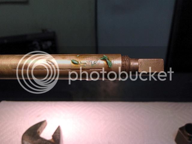
Final photo is staged after cleaning the lap and my hands. I don't like to handle the camera with filthy hands. Next up are the pistons.
Gail in NM
Great description & pictures!
I've always wondered on those commercial barrel laps - as you tighten the end fitting, does it bulge/enlarge the middle portion of the lap body (exaggerated blue line) and you pass the cylinder 'over the hill' to finished size so to speak?
Petertha: The short answer to your question about the lap is "yes" for the through hole barrel laps. The blind hole laps expand on the end. This bulge is thought to be a disadvantage by some but it is actually very useful. With a little practice you can easily feel less than 0.0001 difference in the bore diameter as the part is traversed from one end to the other and it is really easy to get a good feel for where the bulge is. If the part "feels" the same over the entire distance then the bore is parallel. If it has a tight spot it is easy to dwell or lap that area a little extra but this is rarely necessary as the lap will naturally cut more in the tight areas.
Where this bulge really comes in handy is in building small compression ignition engines. It is accepted practice to slightly taper the cylinder bore of these engines so the piston fits really tight at the top of the stroke to make a good seal and looser at the bottom half of the stroke for easy running with low friction. On compression ignition engines the compression ratios typically are in the 18:1 range and a tight fit on the piston is necessary as max compression is approached.
To put this slight taper in the cylinder is first lapped parallel to a very high finish. I generally use 6 micron diamond compound on 3/8 inch bore and smaller. Then the bottom part of the cylinder is further lapped to relieve that area by 0.0001 or 0.0002 inch. These are my numbers and other builders may use different amounts of clearance than I do. This tapering is done using the feel of the lap caused by the bulge.
Of course this is not necessary on low compression spark ignition engines such as this build which has a target compression ratio of a little over 5:1.
Gail in NM
Petertha: I assume you are asking about the vice stop in the photo. It is just a piece of 3/8 mild steel that has been ground flat and has a slot for mounting. I am using a Chick 4 inch vice which has the body ground accurately to 4 inches wide by the manufacturer. There are 8 holes in each side of the body that are threaded 1/4-20. The slot is off center so I can rotate the stop out of the way if I need to have stock hang out the side or the stop can be slid up and down if needed. The top is milled down to 1/4 wide to accept clamp on spacer bars that I have made up in increments from 1/4 inch long to 3-3/4 inches to position parts in different places in the vice jaws. The stop is just held in place by a single 1/4-20 socket head cap screw.
Before starting to machine the pistons I turned down a 1 foot as purchased length of 5/8 nominal class 40 grey iron to a uniform diameter so it would fit a collet. Grey or cast iron comes oversize so it will finish up to the nominal size. In this case the stick was about 0.690 diameter so I turned it to 0.672 (43/64) to fit a collet. I do this when I purchase my iron so it is ready to use when I am ready to make something out of it so this was already done and not pictured.
I also made the mandrel to hold the pistons. It serves not only to hold the pistons for finishing to final size but also as a plug gage to use while boring the upper part of the piston next to the crown. For this I made the diameter 0.388 as the loose wrist pins are 0.094 diameter by 0.375 long. 0.388 is the minimum dimension such a pin will fit into if the pin has square ends.
The mandrel was also turned down to a loose fit in the cylinder for the length of the cylinder so when finishing the piston I could make trial fits in the cylinder pushing the piston the full length of the cylinder. To hold the piston in place the end of the mandrel was tapped 2-56 so a screw through the crown of the piston could secure it. The piston will have this hole in it as this screw secures the yoke that mounts in the piston.
Gail in N
To start machining the pistons I first turned down the iron stock for a length long enough to get 5 piston, the 4 needed plus one spare. I roughed it with a center so I could take reasonable depth cuts and then finished it to size with out the center so it would be sure to be turning parallel. I do this when working to close tolerances as any defect in the center hole or tail stock misalignment will not affect things.
As the largest bore of the cylinders was 0.5003 the Iron was turned to 0.5005 to leave about 0.0004 finish allowance to, that is 0.0002 to get it to size and 0.0002 for clearance in the cylinder. A little bit more will have to come off for the smaller cylinder bores.
Then 5 blanks were cut off about will about 0.020 left for finishing the ends.
The ends of each blank were faced off to bring the blank to finished length.
Using a sharp pointed 60 degree threading tool, two labyrinth grooves were cut 0.005 deep near what will be the crown of the piston. These act as pseudo rings by trapping a small amount of oil in them and also help distribute some oil to the upper part of the cylinder.
The piston is reversed and a 0.040 groove is cut 0.010 deep near the lower end of what will be the piston skirt. This groove lines up with the hole from the oil cup on each cylinder when the piston is at BDC and then distributes oil up the cylinder wall.
All the grooves were lightly deburred with 400 grit abrasive paper as they are done to remove any burrs raised by the vee tool or grooving tool.
Before starting to bore out the pistons I had to modify a boring bar. I has bars that were small enough diameter that would not reach the bottom of the bore and ones long engough that were too big in diameter. The bar needed to be small enough in diameter that it could be used to make the bottom of the bore flat so the yoke would have a good surface to bolt up to otherwise it would try to work loose.
With my modified boring bar I bored out the piston to 0.388 diameter and used the mandrel as a plug gage to test the size. Then I relieved to skirt to 0.438 diameter for clearance for the connecting rods.
Reversing the piston, the crown was center drilled and drilled for the screw that mounts the yoke.
The last machining operation on the pistons is to put the countersink in the hole in the crown. There will still be the finishing to size but that will be an abrasive procedure so no chips will be generated and the pistons will still look the same.
The only hard part is getting the countersink depth right so the head is flush or slightly below the surface. Here is what works for me.
I position the tail stock so the counter sink will hold a metal strip in place and zero the tail stock quill dial. I use a machinist 6 inch rule for the metal strip. Then, after removing the rule, I countersink the hole some easy to remember amount that still leaves the countersink undersize. I knew that 0.100 was a safe number in this case. Then the piston was removed and a screw inserted in the hole and I measured how much it stuck up. 0.009 inch was the magic number. The piston was put back in the lathe and the tail stock was zeroed again using the rule. Then the tail stock was advanced 0.110 to give an extra 0.001 to be sure the screw did not protrude.
For the rest of the pistons all I had to do was zero the tail stock with the rule and then advance the tail stock 0.110 to cut the finished countersink on each one.
To finish up, I rubbed the crown against some 400 grit abrasive paper to remove any burr thrown up by the counter sink and then did a finger twist of the counter sink inside each piston to deburr the hole.
Gail in NM
Fitting up the pistons is one of the easiest operations on the build. But until someone has done it a few times it's a bit of a challenge to get the right fit. That's because it's a feel type of thing and how do you tell some with words how it should feel like. Easy enough if you are showing them in person on a machine.
First off I engraved the bottom of the cylinders lightly with the numbers 1 to 4. These will be the position they go in on the engine later and will also let me keep track of what pistons belong to what cylinder. Then I sorted the cylinders for bore size. When fitting the pistons I start with the largest bore first so if I make a piston too small I can use it in the next size down cylinder. When I get to the last cylinder then thats one reason why I made a spare piston.
A piston is mounted on the mandrel with a screw holding it in place. Using a strip of flat metal to back it, I started with 400 grit abrasive paper and a few drops of oil. With the lathe running at about 800 RPM I press the abrasive paper against the piston using both hands and apply about a 1/2 pound of pressure. I oscillate the paper back and forth along the length of the piston while keeping the paper with it's backing strip flat against the piston OD. After about 15 or 20 seconds I clean the piston and try it in the cylinder. I repeat this as necessary until the piston starts to enter the bore. Then I switched to 600 grit paper and repeat until the piston will fully enter the bore with firm pressure. Switch to 800 or 1000 grit paper and repeat until the piston can be slid length of the cylinder with about 3 or 4 ounces of pressure. I repeated with 1500 grit paper until it was fairly easy to slid the piston the length of the cylinder with about 1 ounce of pressure. Before each trial fit into the cylinder the piston was cleaned using mineral spirits and a paper towel so no abrasive residue could be transferred to the cylinder. Finally with some light oil on the piston I ran the lathe at about 300 RPM and slid the cylinder back and forth along the piston for about 30 seconds to make sure that it felt even the whole distance and to knock off any high micro spots. When rotating the piston fill slid much easier than when not rotating. After cleaning one more time the piston is removed from the mandrel and the crown is engrave with the number of the cylinder it is mated to.
Now repeat for the other pistons. Sorry for this to be so wordy but there really is not much to see in photos. It took much longer to write this than to do all four pistons. The first photo is staged and there is no oil on the piston. The metal strip supporting the paper is about 1 inch wide. In the second photo it's a little hard to see but the two cylinders in the foreground are number on the mounting flange and the two pistons in the background are numbered on the crown.
Gail in NM


")