Model I.C. Carb with Throttle

Home Model Engine Machinist Forum

Help Support Home Model Engine Machinist Forum:

This site may earn a commission from merchant affiliate links, including eBay, Amazon, and others.

Brian Rupnow

Design Engineer
Project of the Month Winner
Joined
May 23, 2008
Messages
14,971
Reaction score
8,253
Location
Barrie, Ontario, Canada
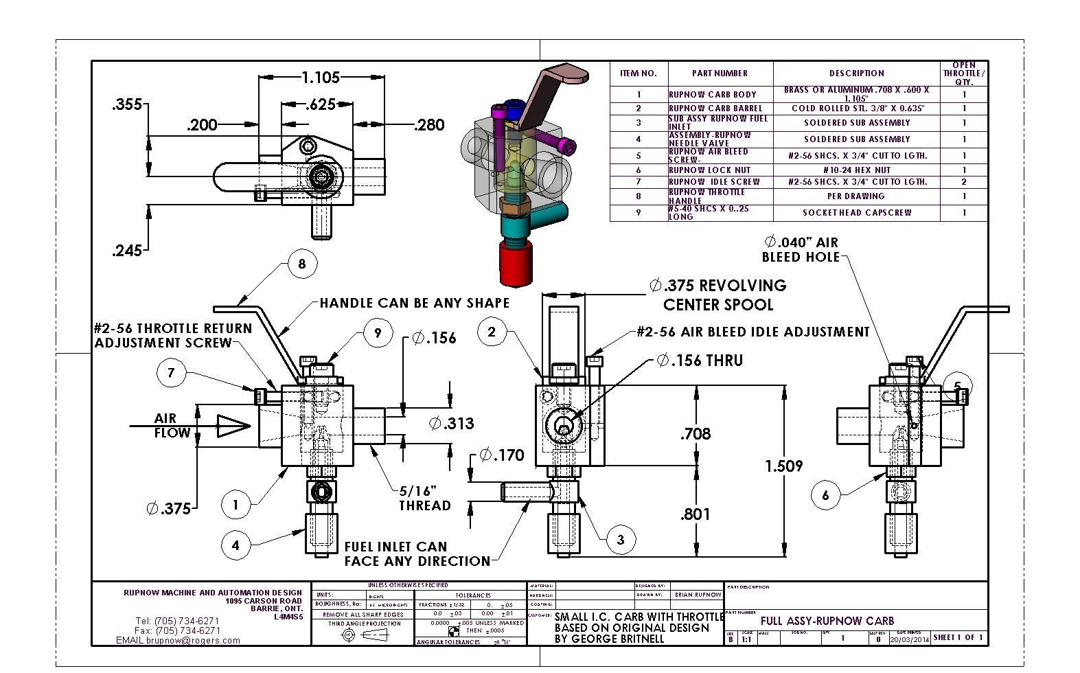
Myself and another fellow from the HMEM forum have been doing a lot of research to find a small I.C. carb with a throttle on it. Hit and miss engines do not have a throttle on them, as the speed is controlled by the governor system. There is no throttle in those carbs--they run "wide open" all the time, as anyone can attest to who has ever had the misfortune to have the governors stick on their hit and miss engines. However, not all of the model engines we build are hit and miss style. Now don't get me wrong.--There are lots of carburetor designs out there for I.C. engines, but they are HUGE compared to the size of the engine itself. We have been searching for carbs that won't look out of place on engines from 1/2" to 1" bore with a single cylinder. After looking at many different plans, we have decided that the best design out there is a design originally put together by George Britnell for use on his 4 cylinder engine. The only fly in the ointment is that George's carburetor has a relatively large bore in it at 0.260" diameter. On the small I.C. engines that I build, they depend on air flow thru the carb venturi to create enough vacuum to pull fuel up to the carb from the fuel tank. If the bore of the carb is too large, the resulting vacuum created by too large a carb bore compared to the engine displacement won't create enough venturi vacuum to suck up the fuel to the needle valve spray "nose". I have taken Georges carburetor and redesigned it to accommodate a bore of 0.156" in the venturi area. This has allowed me to make the overall carb body smaller and to make the attendant air bleed screw and idle speed screw smaller as well. George knows I am doing this, and has even offered up some helpful advise. I am going to build this carb, and use the Webster engine I built a few years ago as my "test bed". Stick with me, and I will post detail drawings as I progress. It will probably be safer to wait until the end of the build to actually download any drawings, because they may change as this thing develops.----Brian
http://s307.photobucket.com/user/Br...w013/FULLASSY-RUPNOWCARB_zpsacdb7dd1.jpg.html
 
Last edited:
Well, I think that covers everything I am going to do in the lathe. Started out with 3/4" square brass, mounted it in the 4 jaw, and turned the big end spigot to finished diameter but about 1/2" long. Put 3 jaw on chuck, reversed the part and held it by the round spigot to turn the other end to 5/16" and left it about 1/2" long. Threaded o.d. of small spigot and drilled 3/16" dia. hole thru all, then reversed part and put threaded spigot in 3 jaw. Drilled 0.260 dia half way thru from big end, then faced big end off to correct length and bored taper as called for on drawing. Removed part from lathe, ran a 0.2" thick nut all the way down the threaded end and ground off anything sticking out past the nut away on my stationary belt sander.

 
Well There!!! That wasn't so bad. The biggest worstest part is finished. Its too bad that my camera picks up all the filings as well as the part I am trying to show. It certainly is a tiny little rascal.
 
And the next part of our saga looks like this. I decided to go with steel for this part, because I was afraid that aluminum or brass wold "gall" and seize in the brass outer body. (It has to turn freely). When I put the 0.375" hole in the brass body I used a 3/8" endmill, so my hole is a couple of thousandths oversize. I will turn this part from 1/2" dia. cold rolled steel, because round cold rolled in its stock form is about .0005" undersize and I don't want a sloppy fit. I know the drawing calls for 0.375" diameter but I will probably end up at .376 when I make the part.
 
Last edited:
Brian, thanks for posting your work on this downsized carb. I've been wondering about a good combination of materials for the barrel and body. Steel is worth a try.

Regards,

Chuck
 
So---Now we have two parts. You may notice that the top of the barrel doesn't quite agree with the drawing. As I was about to cut it to length I had a revelation---The single bolt which holds the throttle handle on is right on the center, and the handle is sure to spin on that bolt instead of turning the barrel. What better time to make the barrel a shade longer and put a 1/4" slot on the top. Align the slot with the hole thru the barrel and I have a quick visual reference of whether the throttle is open or closed. The handle will fit down into the slot. I am going to post an updated barrel drawing as soon as I finish this post. That Canadian quarter in the picture is the same size as an American quarter.--A really nice feature of this carb (Thank you Geo Britnell) is that the #2-56 bolt that interacts with the slot in the barrel has two functions. It acts as a throttle stop, to adjust how far the throttle can close before being stopped by the end of the bolt, and the side of the same bolt holds the barrel in place so it can rotate but not fall out.---Very nifty "dual purpose" design. The hole thru the barrel is 0.156" diameter. As for the end view---If that hole in the barrel doesn't appear to be perfectly concentric with the hole in the carb body, well----That is a testament to the fact that I am much further advanced in my design capabilities than I am in my machining abilities. A sharp eyed individual will also note that my taper in the intake side of the body doesn't nicely taper to a matching diameter with the hole thru the barrel. That is because of constraints imposed by the .040 diameter hole thru the side of the carb body which is part of the idle circuit. The law that governs how a venturi in a carburetor creates a low pressure area where there is a restriction in the airflow, (to suck fuel up hill from the gas tank) doesn't explicitly state that it must be a smooth and seamless transition from the large diameter passage to the small diameter passage.--Also, the nose of the needle valve outer shell is going to stick up in the center of that 0.156" diameter, causing a further restriction in the air passage. If there is a problem, I will machine a nicely tapered insert and put it in the intake side of the carb body.

 
Great drawings, and great work, Brian. Thanks for doing this, and I'll be following all the way!
 
The needle valve itself is of two piece construction. There are no threads on the fabricated "needle"--The threads are on the inside of the cap.


I had asked George Britnell a question about the location of the air bleed hole location and throttle opening here, but now realize that George had answered me in a previous email. It just took me until this afternoon to get my head around what he was saying.
 
Last edited:
Why do you feel its worth the expense to get 10-40 threads? Wouldn't 10-32 be fine enough? Thats a standard that any hardware store has.
 
-Every set of carburetor plans I have ever seen ask for 40 tpi pitch on the threads that control the needle valve. I have always used taps with 32 tpi. I can only assume that the added control of fuel flow that you get from those extra 8 threads per inch must be very important, as all the carburetor guys use them in their plans. I may also be a gullible fool.-I have decided that anything I can do to make my carbs work better is probably worth spending the money on. Only time and experimentation will tell.
 
I know, I know---I said to make the handle out of steel. But when I got to my "cupboard of all bits and pieces" the only 1/16" stock I had was brass. I don't think you can bend brass too readily without it breaking, so I heated it up with my oxy acetylene torch till it was dull red and then bent it in my vice. I'm somewhat amazed at how few pieces there are to this carb. All that's left to make is the fuel inlet and the needle and cap. I might solder up the fuel inlet tomorrow and get it ready for when my taps and dies arrive.

 
Okay---At this stage of the game, I am beginning to realize that ---I muffed it!!! On the carburetor main body, the "thru-hole" that the air flows thru has to be the same diameter both entering and leaving the round central chamber where the throttle barrel is.--Otherwise, as I have just figured out (much to my dismay) the amount of opening or closing on one side of the barrel (for instance the inlet side) is totally different than the amount of opening or closing on the opposite side. I am going to have to reconfigure the main carburetor body--as in redesign and remake it. That's okay. I'm learning as I go along here. I think I can save the barrel and the handle.
 
There wasn't a lot of redesign involved. I made the hole thru the air intake side the same diameter as the hole in the air outlet side at the point where it breaks into the 3/8" hole that the throttle barrel fits into, and moved the air bleed hole and screw around a bit to optimize their location according to advise from Geo. Britnell.---George had sent me this information earlier, but I couldn't really get my head around what he was saying until I read thru it again today while I was puzzling things out. I can re-use the barrel and handle.--Interestingly enough, this throttle goes from closed to open in 45 degrees, unlike the butterfly valve in an automobile carb that must rotate thru 90 degrees.
 
This morning, before diving headlong into another piece of brass, I am doing a bit of taper experimenting. I wanted to know if I can drill a 20 degree included angle taper thru material 0.361" thick and go from a diameter of 0.315 to a diameter of 0.187". My selection of small boring bars is, well, minimal would be a good word. I didn't want to have to make up a special fluted taper cutter. I reproduced the critical geometry in aluminum--a 3/16 centered hole going .361" before breaking thru to a 3/8" diameter cross hole. I found that by drilling a couple of stepped holes first to remove as much meat as I could from the outside end of the aluminum piece without cutting into what would become the tapered hole, I was able to get my much abused boring tool thru and give me the correct taper and correct diameters. That's a big plus!!! Now I am off to my supplier to buy some more 3/4" square brass. The outer body could be made from aluminum, but I like the look of brass better.
 
It's been a looooonnnng day!!! I have remade the brass outer body to the new design, and it looks good.---But---I just found out I can not re-use the barrel. This was a case of two wrongs not making a right. When I made the first brass body, I got something off center. Scratched my head for a minute and thought--"Oh well, I'll just drill the hole thru the barrel off center a bit so it will match up".---BAD MOVE!!! Now the barrel with the off center hole won't work with the new brass body. OH POOP!!! I'm going upstairs and read for the rest of the day. Fresh start tomorrow!!!
 
Nothing picture worthy accomplished today. I spent the whole day messing with sump pump stuff. I wasn't totally impressed with the 20 degree included angle tapered hole that I had machined on the inlet side of the new brass body. So--I turned a 20 degree included angle taper on a piece of 3/8" cold rolled and used some really coarse, nasty automobile valve grinding compound on it to hand finish (can't honestly say "lap" ) the inside of the taper. It turned out quite nice actually. I don't really have any boring tools small enough to bring this off properly.
 

Latest posts

Back
Top