A different opposed piston engine---

Home Model Engine Machinist Forum

Help Support Home Model Engine Machinist Forum:

This site may earn a commission from merchant affiliate links, including eBay, Amazon, and others.
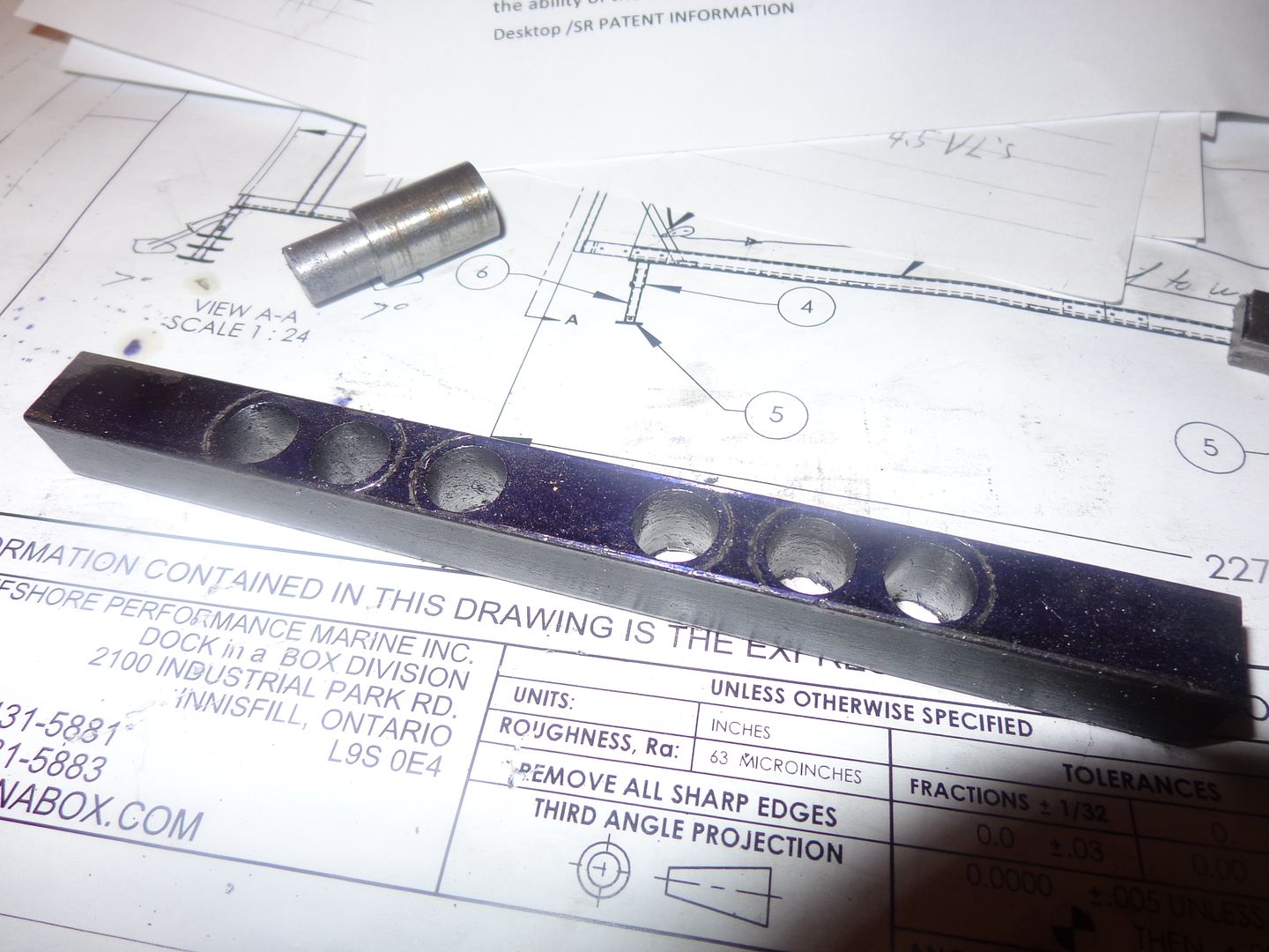
Now we have a step #2. After recoating the side of the drilled part with layout dye, I take a piece of 1/2" dia. cold rolled steel, and turn one end for a "good fit" into the .3725" reamed holes, set it in place, then scribe around the outside of it with my scriber. This gives me my "reference" lines for trimming to length and radiusing the ends of the 3 crank webs. Why didn't I make the end webs out of thinner material?---Because I figure the thicker material is less apt to move when I weld it, and it can be turned to finished size in the lathe after welding, by turning from the non welded side.
 
So----Nothing is welded yet, but it sure do look good!!! The hurting time will come tomorrow after the welding, so I can see how much it pretzels. Actually, the initial mig welding shouldn't move anything. Then I will have to build an alignment fixture before I do the final silver soldered joints.
 
Hi Brian............I did my last chemo treatment last week and I should start feeling better soon
I think that only plug welding would be good enought for this and causing you less work also
drill your counter weight and crank pin "smalle for the crank pin and then fill the hole with the tig
one side would be good enought
 
Hi Luc--Good to hear from you. Hope you feel better soon!! ! All of the joints only get mig welded on one side. (I don't have tig). The last two "welds" made with silver solder will be done with the 3 "part cranks" in a jig t0 keep everything straight.
 
Tomorrow morning I will build a crankshaft jig, to align the 3 sections of mig welded crankshaft for final silver soldering to join the 3 mig welded sections together. The pale green blocks will be drilled and reamed to 0.375", and bolted to a piece of cold rolled steel flatbar 3/4" x 1.5". I will use an 8" length of 3/8" cold rolled round rod to align the two green blocks before bolting them down to the steel flatbar, then after the bolts are tightened will slide the alignment bar out and fit the 3 pieces of crankshaft in place. I have drilled and tapped the green blocks for a single #10-24 set screws to hold things in place. Then I can turn the jig on end and set it in my vice for the final silver soldering of the remaining two joints. I will let it cool in the jig, then unbolt the green blocks from the steel flatbar and slide them off over the ends of the crankshaft. If I have lived a good clean life, I should end up with a perfectly straight and very strong crankshaft.
 
Geez Brian. Last time I looked in on this thread a week ago you were "toying" with this idea. Now you're already into it. Looks interesting to me and should be quite a neat engine when completed.

Cheers,
Phil
 
And now its all over but the shouting!! The silver soldering is finished. The journals were painted with "Wite-Out" correction fluid to keep any unwanted silver solder away. The spacers are in there to guarantee that I end up with the desired 0.28" between the webs. I'm going upstairs now for a drink of rum and egg nog while I wait for everything to cool off. Cross your fingers for me!!!

 
TA-DA!!!!---We have a crankshaft!! Is it straight?--Well, that depends a great deal on where you measure it. When I first took it out of the jig and put one end in the 3 jaw chuck on my lathe, the far end was out by about .030" total indicated runout, as per my dial indicator. That's .015" "out of center". I gave it a couple of light taps with my dead blow hammer, and it moved around amazingly easily, to almost no runout. This thing seems to be amazingly flexible. The good news is that no silver solder migrated onto my con rod journals. Will I be able to use it?--Yes, I expect I will. I doubt very much that I could have had greater success if I had tried to machine the crank from solid.--In fact, given how flexible it seems to be, it would have been a nightmare to machine from solid. I think this will be one of those "Suck it and see" situations where I won't know how successful I was until I have built the rest of the engine.
 
I wonder what it would cost to have the profile water jet cut. There is nothing critical about the profile. I could save it out as a .dxf file.
 
Brian, what material do you want this made out of? I can CNC you a couple rods if you would like.

I was wondering what you were going to do next. I enjoy seeing your engines come together, and ultimately run.

Let me know if your interested.
 
jwcnc1911 --The material would be 6061 aluminum. Where abouts in the world are you? Do you work from a dxf file or do you take the code directly from a solid model of the part.--Brian
 
Last edited:
I'm in N. Alabama. Your SW solid file will be good. I'll generate toolpaths directly from the solid file.
 
A gentleman from Alabama "jwcnc1911" has just stepped foreword and kindly offered to make the two rather complicated links which you see coming out of the ends of the cylinders on his CNC equipment. What a wonderful thing for him to do. A Christmas present I wasn't expecting. I have cleaned up and added some detail to the actual connecting rods that go from the links he is making to the crankshaft.
 
One of the issues that you get into with an engine like this is 'Where the heck do I run the gasline"??--I have floated an idea here that looks like it will work, not foul any of the moving linkages, and not hide any of the moving linkages. I'm not sure about that vertical gas tank though.---I may have to rethink that!!!
 
Tomorrow I will go to my metal supplier and buy some material. I'm going to build all of the big stuff first, so I will have something to bolt the little stuff to as I build it.

 
Back
Top