A different opposed piston engine---

Home Model Engine Machinist Forum

Help Support Home Model Engine Machinist Forum:

This site may earn a commission from merchant affiliate links, including eBay, Amazon, and others.

Brian Rupnow

Design Engineer
Project of the Month Winner
Joined
May 23, 2008
Messages
14,970
Reaction score
8,252
Location
Barrie, Ontario, Canada
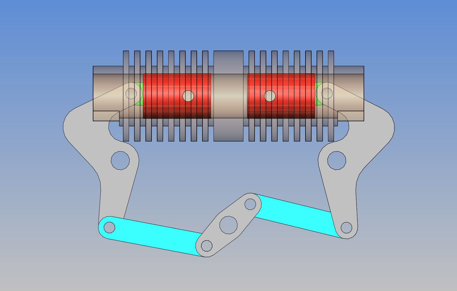
I have been fascinated with a post on another forum about an opposed piston engine. I do not want to plagiarize someone else's post, so I have been surfing around the internet looking at "other" types of opposed piston engines. I found one today, and spent some time doing some preliminary modelling in Solidworks to see what would be involved. I'm not totally sure that this is "do-able" as a model engine, but I thought it was well worth having a look at. This is what I come up with---a 3/4" bore x approximately 1" stroke air cooled single crankshaft engine. I'm not sure if I will go farther with this or not, but it IS interesting.---Brian

 
Brian,
Isn't this similar in concept to the Atkinson Differential engine?
Art
 
Brian, this is the principle of operation of the "rootes" diesel used in the "commer" truck and known as the TS3 engine, it was watercooled and had a blower to scavenge the spent gases when both inlet and exhaust ports were open, there are one or two examples of survivors on "U tube"
best regards Stew.
 
Art--the action of the Atkinson differential engine was different than the action of this engine I am proposing. You have to see an animation of the Atkinson differential to see what I mean.---Brian
 
Okay--I wasn't 100% sure that this would work with a conventional crankshaft, but it will. My 3D models are not correct in all cosmetic aspects, but the parts which count, i.e. widths and center distances, etcetera are spot on. I can animate this in Solidworks and everything goes round and round without crashing, just as it should. The big ugly looking part, grey in color, has an offset in it which means that the blue "connecting links" are far enough apart not to hit each other and to allow a bit of space between them for a center crankshaft bearing if I decide that I need it.
 
Brian, there was an engine of that kind in Germany 80 years ago called "Balance-Motor" by OTTO GRAF.
The balancer ("ugly grey part") was seated with an excenter to automatically change the stroke during operation, which was controlled by the vaccum in the induction manifold.
Thus the engine had the same effective compression ratio over a wide range of throttle angle and rpm, resulting in good fuel economy over a wide range of rpm even with smaller loads.
If you're interested in this topic, you might do some research on the "Balance-Motor" by OTTO GRAF. Search for EUDELIN, too.

Edit: You want to have a look at Patent DE 476625 C
 
Think I see how it would work but not sure - assume there is an inlet/exhaust of some kind for steam/air/fuel in the center between the pistons? Looks like it should be interesting to watch it run.
 
Interestingly enough, everything seems to go together amazingly well. That being said, as you can see I haven't modelled in the valves, cams, nor timing gears yet, nor the flywheels. I think I may make the intake valve an "atmospheric" type, same as I have used on many hit and miss engines, so it won't need a cam.--And yes, you are correct, the sparkplug and both valves fit in the center between the two cylinders. I couldn't see any good way to mount everything with one long double ended cylinder, so that has morphed into two cylinders and a center plate which will have the sparkplug and valves mounted in it, and also give me a way to support the cylinders. I may go with only one flywheel, out on the back side of the main vertical support plate. I will probably spend another $100 and buy a complete ignition package with batteries, etc. from Roy Sholl to provide my spark. Of course, if I do go ahead with this engine, I will provide the blueprints to anyone who is interested. I will probably post drawings as I go along, but its much safer to wait until I have a running engine and have made any required updates or changes to the drawings. Then I will post a download link to all of the drawings as pdf files so you won't need any specialized software to open them.

 
Here we have a couple of cross sections through the center of the cylinders. One shows the pistons almost at "Top Dead Center"--they will actually be flush with the inner ends of the cylinders when they are at top dead center. The other shows the pistons at "Bottom Dead Center".--And yes, there is a slot in the outer ends of the cylinders to provide clearance for the linkages. The slot is less than 3/4" wide, so the piston will be fully supported even in this extreme position. The piston rings (which I have not modelled yet, nor grooved the cylinders for) will not go back far enough to catch the rings on this slot. Each piston will have one Viton o-ring.

 
Well there!! That's enough silliness for one day. I managed to squeeze in a set of timing gears, a camshaft, and 95% of the exhaust valve train. I have hidden the one standoff that would normally obscure the timing gears, just so you can see better how things are mounted.---Brian
 
Just did a final volume check, and without taking any valve lead, lag, etc. into consideration, the compression ratio will be 5.4:1
 
Aha!!!--Seems that we do have room for two valves and a sparkplug in there!! It just took a bit of wiggling. The exhaust valve is cam operated, the intake valve is atmospheric.
 
This is a section taken through the center of the cylinders, and coincidentally through the center of the exhaust valve and valve cage. I have added the groove in the pistons for the Viton o-ring. The pistons never get any closer together than what is shown in this section view, and when they are fully at the other end of the stroke, the rings never get close to the slot in the rear of the cylinders. You can see where the exhaust exits through the right hand side of the green 3/4" block which holds the cylinders. I have not shown the exhaust pipe yet. The intake valve would be pretty well identical in a section view, except for the fact that it is an "atmospheric" valve, needing no cam to energize it, and the port which leads to the carburetor faces out the opposite side of the green 3/4" block from the exhaust port.
 
As luck would have it----I was just getting warmed up with this new engine design because I don't have any "real" engineering work at the moment. This morning I got a panic stricken call from an inventor I do business with, who is "Just going to die!!!" if he doesn't get a new thing patented before the end of the year. (I don't know why.) At any rate, he needs a bunch of drawings to submit with his patent request----And he needs then RIGHT NOW!!! Ah well, I never could turn down money!!--Engine development may slow down a little bit for a while.
 
Back
Top