


Philjoe5
Well-Known Member
- Joined
- Jul 12, 2007
- Messages
- 1,727
- Reaction score
- 321
[FONT="]I have some series 7000 T6 aluminum that Ill be using for the con rod. Its great stuff, and machines really well. I also bought some of this aluminum in round stock to make a piston for this engine but more on that later.[/FONT]
[FONT="]The con rod is two parts of course, with the end cap attached to the rod with 8 32 screws.[/FONT]
[FONT="]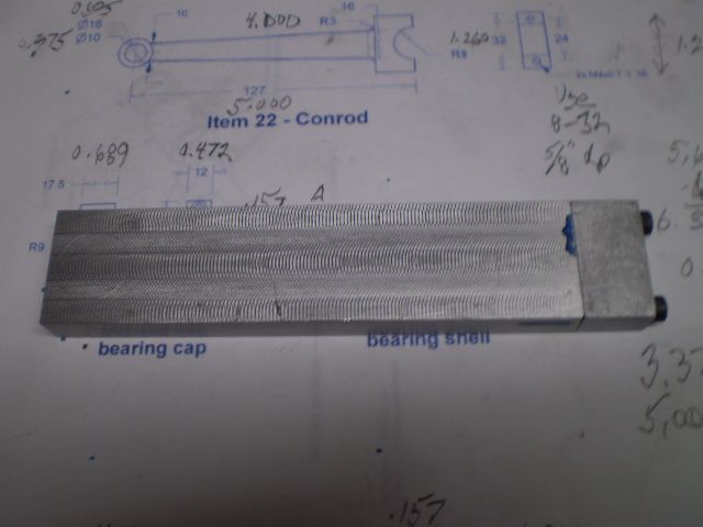 [/FONT]
[FONT="]Then the two critical holes are reamed 10 mm (small end) and drilled/bored 18 mm (big end). For the small end I used a 0.375 reamer but bored the big end as specified in the plans.
[/FONT]
[FONT="]I did some calculations to locate the limit holes for radiusing and milling operations. [/FONT]
[FONT="]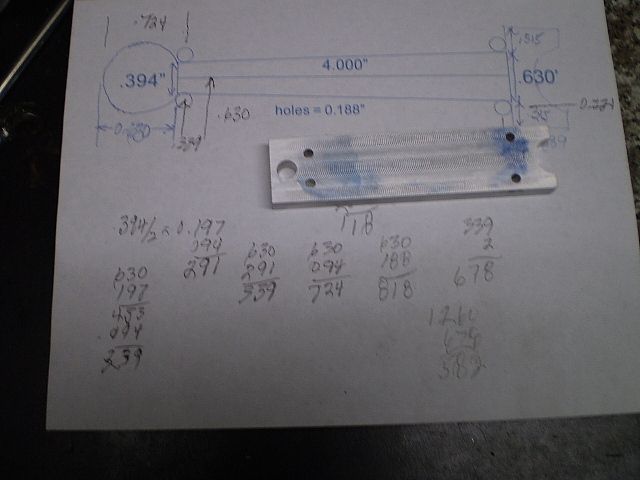 [/FONT]
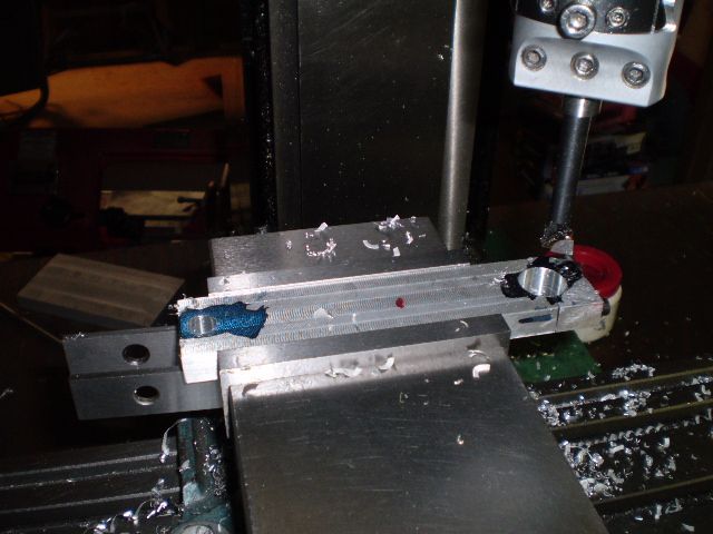
[FONT="]The rotary table is used to form the small end. The angle of the con rod is between 1 and 2 degrees and I dont have an angle block in fractional sizes so I decided to scribe a reference line between the limit holes and mill to that line.[/FONT]
[FONT="]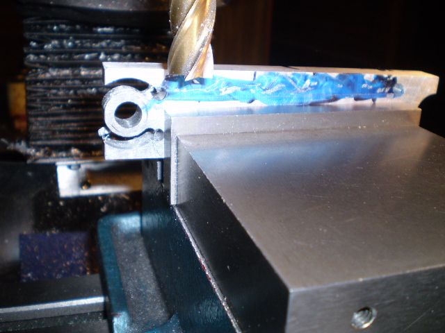 [/FONT]
[FONT="]The finished product is shown and is complete except for the bushings on either end:[/FONT]
[FONT="]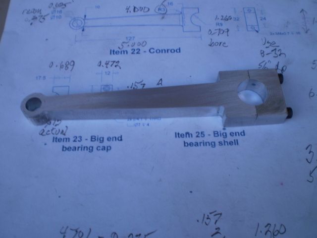 [/FONT]
[FONT="]Ill work on the bushings this weekend.[/FONT]
[FONT="]Thanks for looking in[/FONT]
[FONT="]Cheers,[/FONT]
[FONT="]Phil[/FONT]
[FONT="]The con rod is two parts of course, with the end cap attached to the rod with 8 32 screws.[/FONT]
[FONT="]
[FONT="]Then the two critical holes are reamed 10 mm (small end) and drilled/bored 18 mm (big end). For the small end I used a 0.375 reamer but bored the big end as specified in the plans.
[/FONT]

[FONT="]I did some calculations to locate the limit holes for radiusing and milling operations. [/FONT]
[FONT="]
 [/FONT]
[FONT="]The rotary table is used to form the small end. The angle of the con rod is between 1 and 2 degrees and I dont have an angle block in fractional sizes so I decided to scribe a reference line between the limit holes and mill to that line.[/FONT]
[FONT="]
 [/FONT]
[FONT="]The finished product is shown and is complete except for the bushings on either end:[/FONT]
[FONT="]
 [/FONT]
[FONT="]Ill work on the bushings this weekend.[/FONT]
[FONT="]Thanks for looking in[/FONT]
[FONT="]Cheers,[/FONT]
[FONT="]Phil[/FONT]


