PMR Horizontal Boiler - A Riveting Build

Home Model Engine Machinist Forum

Help Support Home Model Engine Machinist Forum:

This site may earn a commission from merchant affiliate links, including eBay, Amazon, and others.
After thinking through all of the suggestions here and on MEM
www.modelenginemaker.com
I decided that the best solution for me, from both a time and safety view, was a call to PMR to order a new shell, end plates and steam dome. Two days later it was here.
 
aww crap man, I didnt see it until it was pointed out...
 
Stuff happens, but then it's done and we move on.
I didn't see it either (until I got a PM that said "I think your end plates are upside down")
 
Now that you are not needing the first boiler body. You could give "milling the heads of the rivets off" a try, and see how well the endplates match up with the rivet holes when all is rotated 180 degrees. It would make an excellent practice piece for soldering(caulking) practice. :)
 
That is my intention. I'm so used to silver solder that I need to back off on the heat, etc. so a practice boiler will be useful.
 
Stan, are my eyes playing tricks on me? I thought I saw you attaching the steam dome with layout blue sandwiched between the boiler shell and the dome.

If I am correct, I'm wondering how soldering will pan out. Surfaces should be scrupulously clean before soldering. Therefore, shouldn't they be cleaned before assembling with rivets?

Please excuse me if I'm mistaken.

Regards,
Orrin
 
Hope you didn't miss the thrilling "I riveted the end plates on upside down" episode. You are correct. That boiler is on the shelf and the new one is progressing. In addition to cleaning meticulously, I've fluxed before riveting this time. Thanks for noticing. First boiler. Learning a lot.
 
Stan,

I know how you feel, boilermaking will either drive you "to the nearest bar for an infinite number of boilermakers" or you with a great boiler and divorce papers pending citing "neglect, he's run off with another woman and she's made of copper"

"an infinte number of holes, an infinite number of rivets" and an infinite number of ways to screw it up

And to really rub it in you are working with copper, which is expensive, does not like to be drilled, and REALLY does not like being threaded

As a fellow sufferer I sympathise but so far you are doing great (I too have written off some pretty pricey bits of material)

Regards Mark
 
Last edited:
Back on Track

The recovery is complete. We now return you to your regularly scheduled boiler build.

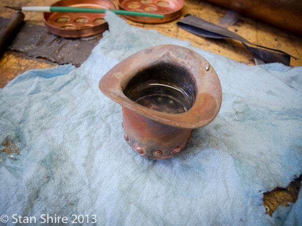
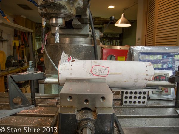
Ready to go. This time with the end plates correctly oriented.


Although I won't show steps that I've already covered here, some refinements for your viewing pleasure.

I turned an internal spacer for the dome.


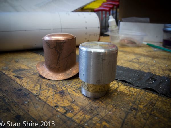
It's also used with a mill stop to fix the dome cap in position until a few rivets are in to hold it.


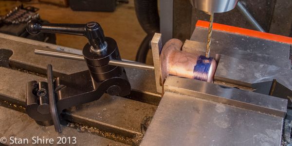
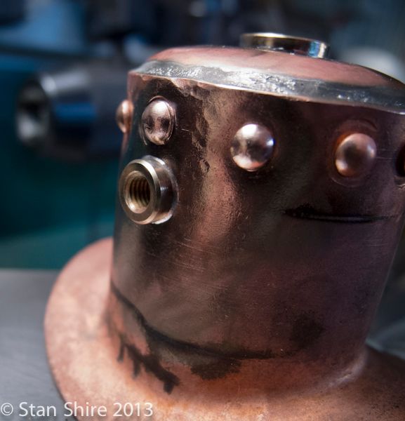
With the first two holes drilled, I'm ready for the rivets. Per Jo's instructions, I'm fluxing as I go. (Yes, I did remove the Dykem blue as soon as I took this pic.


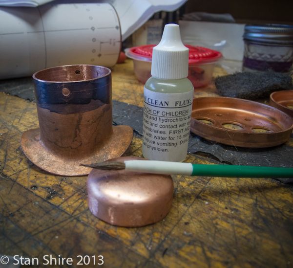
After riveting, cleaning, more flux and soldering, I did (also thanks to Jo) leak testing as I went. No leaks here. FYI. I spoke with PMR about what kind of solder is supplied. It is Harris Stay Brite. 96% Tin, 4% silver.


Next, the dome was drilled for three threaded bushings. I wired them in place with iron florist wire. The grey stuff around the bushing is anti-flux to keep things a bit cleaner.


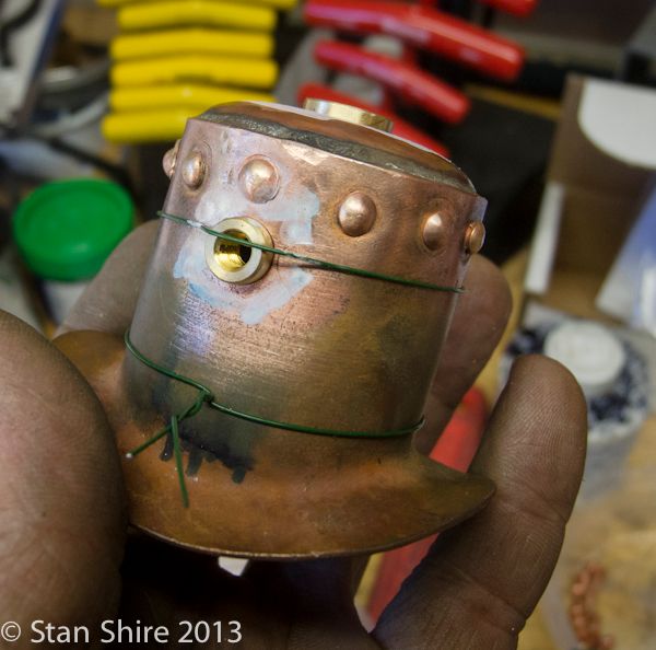
I heated the outside and applied the solder on the inside of the dome. It flowed through very nicely.


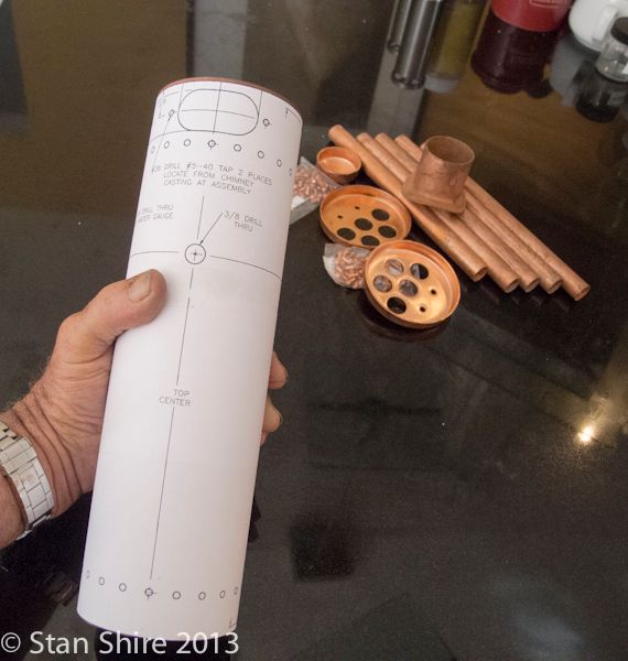
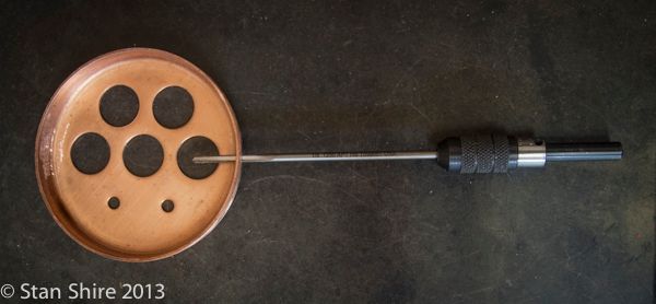
My addendum to PMR's template. My attempt at not doing anything stupid this time around.


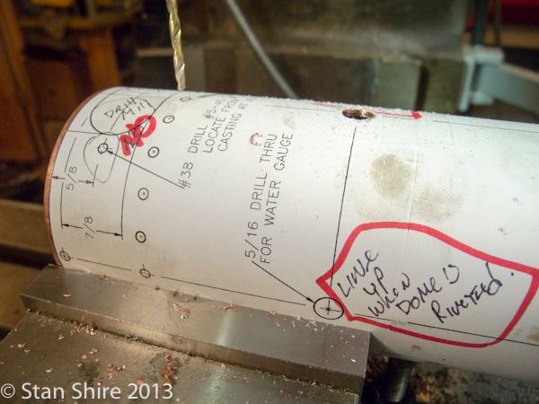
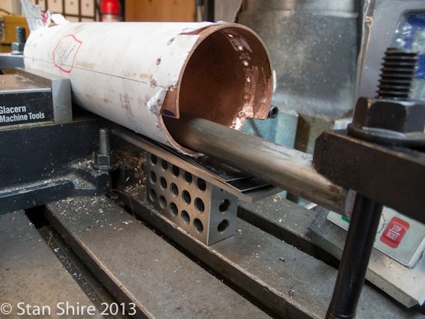
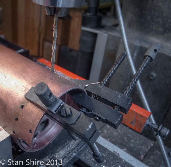
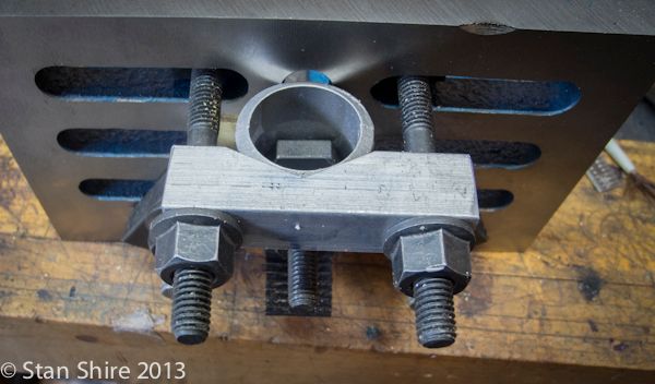
On the original shell, I wasn't happy with the setup for holding the tube for drilling and milling. This is much better. Rock solid. A cold rolled round, both ends flattened and clamped solidly to the table.


Lining up the ends plates VERY CAREFULLY this time.


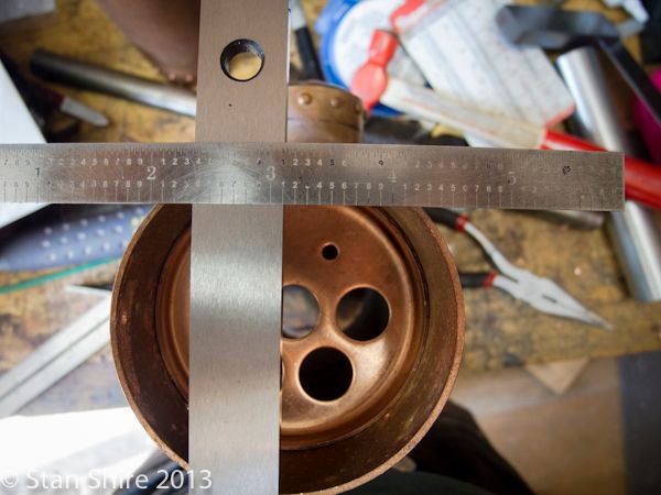
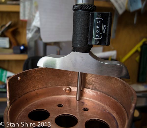
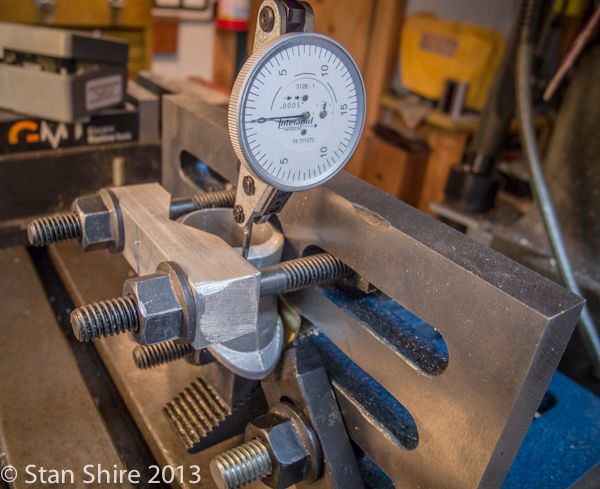
Another height gauge to position the plate.


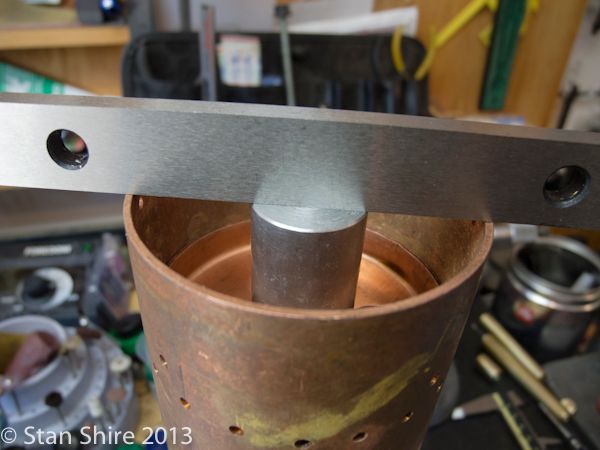
And a few clamps to keep it in place until a few rivets are in.


A double-check. Bang on.


I remembered on the first build, that the rivets were a PITA to get through the drilled holes. A .125 reamer in a pin vise solved that issue.


The rest of the riveting proceeded as before.

With the shell riveting done, I moved to the chimney casting.

You may have read the "Boring Question" thread. With a great deal of help and suggestions, I followed Steamer's procedure for making an expansion mandrel to hold the casting. Thanks, Dave!
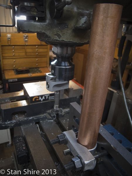
But before I could do that, I needed to bore the casting to fit the chimney.

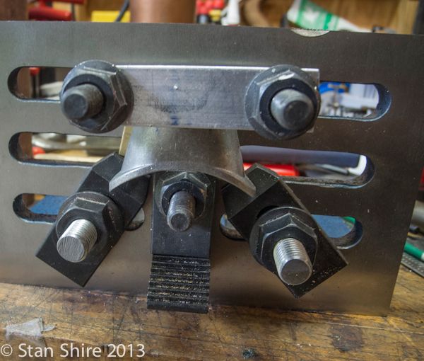
Taking no chances, I made a V block for the angle plate, one clamp on the inside of the casting, and two more to prevent any rotation.


Indicated the bore.


Other than making sure that it worked, I'd never REALLY used the Bridgeport's auto quill-feed.
I set the movement at the lowest feed of .001 per revolution. WOW! it's very spooky watching that.

A short film.

[ame]http://www.youtube.com/watch?v=6PsUkBCpXCo[/ame]

And, a perfect sliding fit.


With that done, I could now finish the mandrel.
Turned a some 6061 to slightly over the ID of the casting.


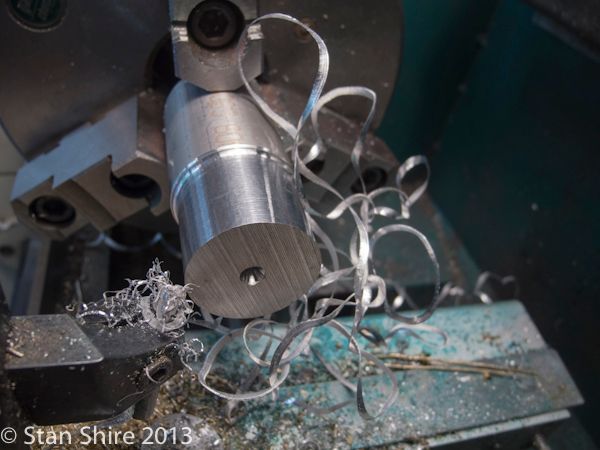
Drilled and tapped ¼ NPT.


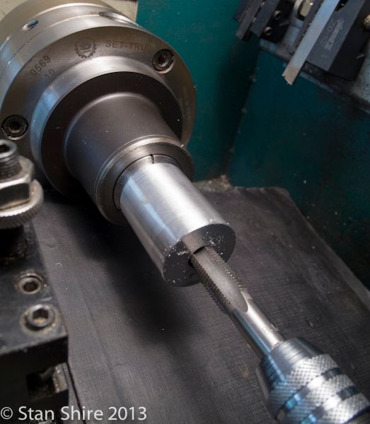
Two cuts through, front to back at 90 degrees for the expansion slots, then back to the lathe to turn down to just under the ID. This was with the ¼ NPT plug in place.

On like it's welded.


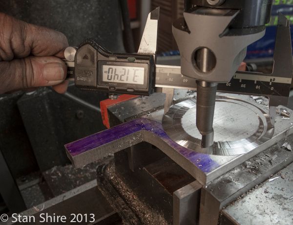
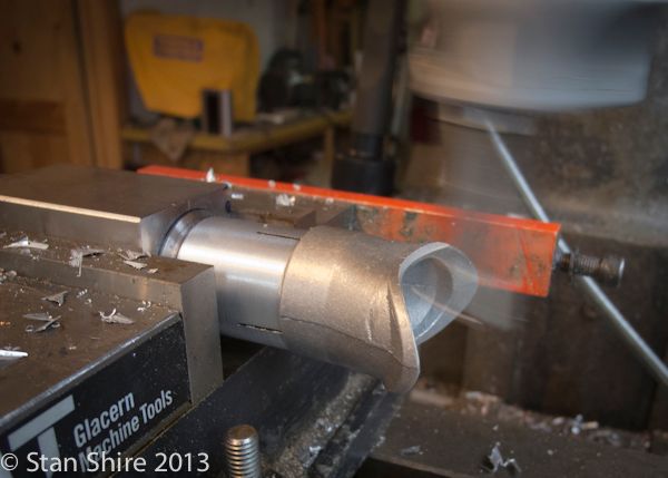
I had some excellent suggestions to set an interrupted cut to a radius in the drawing. (See the "Boring Question" thread). In the end, I just put a piece of plate in the vise and "scratched" the surface with the boring head. Measured, moved the boring bar out based on the reading and hit it dead on in three tries.


Then, centering the mandrel on the Y axis.


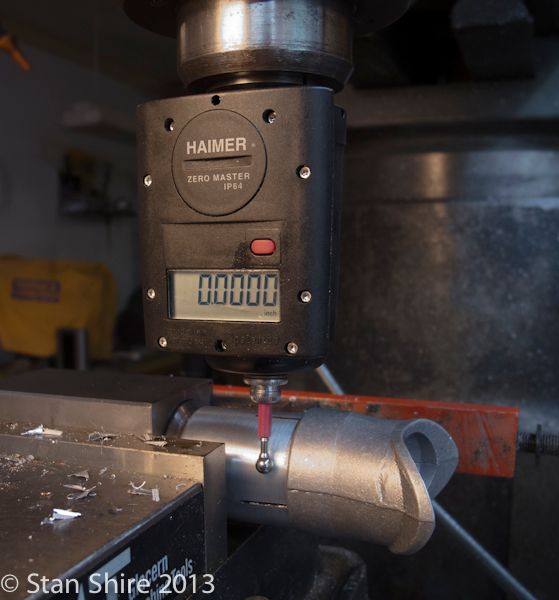
And making the cut with the auto feed


Another video of this op.

[ame]http://www.youtube.com/watch?v=UqBrOTPCQ5w&feature=c4-overview&list=UUtv2FL7ehRo9CV-vt2kPlWw[/ame]
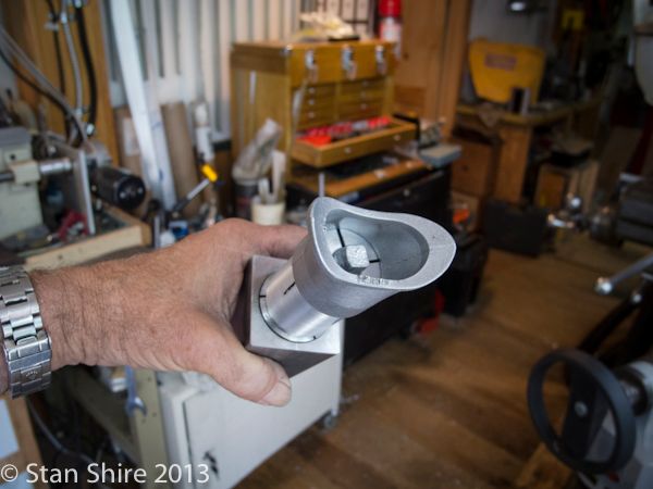
It fits!


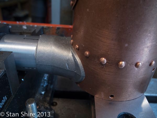
Starting to look like it could be a boiler.


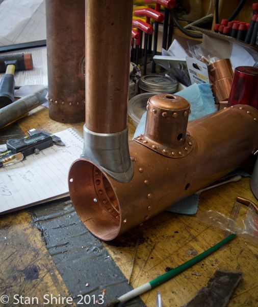
Tomorrow, I'm hoping to get the tubes and stays in place and soldered.

Thanks for being patient while I got back on track.
 
looks very much like a boiler to me,

I love your steam dome nice close rivets

a quick flash with the torch (plenty of flux) get it to good red and a quick few dabs of Easy Flo,

JOB JOBBED

Nice clean joints (like yours) and the silver solder will suck itself in ( high S to B factor , family forum so P.M. if you don't know the expression)

Carry on boiler baking you'll get there
 
Got the hydro test done yesterday. No leaks!! Held pressure.


Water tank and Displacement Lubricator

Since the water tank and displacement lubricator are accessories for the boiler, I decided to put the build here. If you guys think I should also post them as separate builds, I can do that.

The tank shell and bottom are exactly the same size as the boiler and end plates. Good thinking by PMR. The shell is soft soldered inside the shell. Sorry, didn't take pix.

The base casting almost fit inside the tank shell, but needed a bit of reduction in girth. Onto the 3 jaw and quick work to make a good fit.


Two holes are drilled, 180 degrees apart, for screws to attach the shell to the casting.


And one hole for the ¼-40 bushing which will be soldered in. Note the soldered-in tank bottom.


Then mounting holes are drilled in the base casting.


As usual, I thought the tank top looked "unfinished." A decorative ring for the top started with marking out and cutting a rough circle in 6061 plate.


Then, using one of Bogs' techniques, I taped the back of the plate to get some friction against the chuck jaws.


A live center for pressure and light cuts to true up the outside of the circle.


Then, with the outside diameter true (enough), I clamped the disk in the 3 jaw and used my biggest bi-metal hole saw to hack out the center.


The boring bar cleaned up the hole to the diameter I wanted.


Using a round over bit, I rounded one side, flipped the disk around and did the other side.


And finished up with this. Much happier with the top now.


Still haven't decided on paint or polish for the copper.

Bogs to the rescue again. John sent me some of his classic CoC drawings of displacement lubricators.

Cleaning up a 0.6250" brass rod.


Drilled nearly all the way to the bottom and tapped 3/8" deep.


Bling in progress


After threading a ¼" pipe ¼-40 at both ends, a 1mm hole is drilled. This is the cross pipe and the hole is to admit oil.


The cross pipe is soldered in and a top with o-ring is made. I really have to improve my knurling.
I do know about calculating the diameter for knurling and will probably remake the top.


Now, tomorrow its back to the boiler firebox and associated castings.

Stay tuned.
 
Closing in

Most of the morning was spent with wet/dry paper, emery cloth, buffing wheels and files, but I have the shell to a point where I'm happy with it.


Too much time was spent removing my excesses of solder around the steam dome. With various files, I managed to remove the solder. In fact, I prefer the term "fettling" to "filing." It's so Dickensian. "Mr. Cratchett! When you finish with those accounts, there's fettling to be done."

So, onto the firebox castings.

The doors were put in position and marked where they would need fettling. There is not much to do as the castings are first rate and fit fairly well.


The hinges will need a good rounding over also.


So off to Oliver to fettle.


A few fettles later


A few minutes more with Oliver and the fitting is finished.


Drilling the 1/16" holes for the hinge pins. I had the bit as far out of the chuck as was possible and managed 3 hinges deep.


Fortunately, in one of my few moments of thinking ahead, I had ordered a few 1/16" aircraft drills. Obviously for a very tiny aircraft.


BTW, the casting couldn't be inverted to do this. A lip at the top extends out further then the hinge pin position.

I did manage the top three holes with a thou-over reamer because the 1/16" brass rod for the hinge pins seemed too tight. The bottom hole just made it with the reamer in a pin vise and hand turning. Now it's a light press fit.


It looks like I should be able to fit the firebox upper doors and rear casting machining and drilling tomorrow if all goes well. We may have a test fit, all together then.
 
Hi Stan

It seems as though boilermaking hasn't driven you completely potty and your boiler is lovely.

What pressure is it to run at ?

Those firebox door hinges look a bit tricky.

A quick pic of a bit of riveting done by a better boilermaker than me (my Dad) these are 1/16" rivets in 1/16" M.S. Plate. How he got into those corners heaven knows

DSCF0002 (2).jpg

Regards Mark
 
Mark
Your Dad's riveting shows that he's done far more of that than I will ever do.
The corner rivets must have been done with a dolly purpose-made for them. Amazing.
Actually, the hinge leaves are in the casting and just required some cleanup and drilling. I did run a DTI up the front and side before drilling to make sure that the holes would run true.
The holes for the doors are secured in position and use the previously drilled holes as guides. So, hopefully, all will align.
 
As I was putting in the door hinge pins, it occurred to me that I have, at this point, a working boiler. Needs a lot of finishing; paint, some other odds and ends (or bits and bobs), but it could actually make steam.
It does.th_wav

[ame]http://www.youtube.com/watch?v=9iJ0meOOqEQ[/ame]
 
Becoming Unhinged

First, thanks for all the comments. ArnoldB said that there is something about an engine running on steam. I never realized how amazing it is. I like engines that have lots of things moving. Probably why I added a propellor to Elmer's 3 cylinder radial: nothing happens to suggest the engine is even running, other than the rotary valve behind the plexi valve cover.
Adding steam to the mix is like a 3 ring circus. Lots happening in many places.

So back to the build. This is where we last saw the engine.


Actually, it was here, at the garden party.


The upper doors and casting being fettled.


And post-fettle.


I was able to make good use of my woodworking clamps.


With the doors clamped in position, and using the casting hinge pin holes which had already been drilled, these holes guided the drill in making hinge pin holes in the doors.


I did straighten the doors before drilling.


After polishing the shell, I was very careful not to put more scratches in while I drilled for the chimney casting screws.


When I was adjusting the burner flame, the burner kept trying to escape. It really needed something to fix it in place in the firebox. The first step was marking the position for the burner tube in the firebox.


And then drilling in the rear casting.


The Bix Burner in position.


A 1"x1" x .5" piece of brass thru drilled for the burner tube then cross-drilled and threaded for setscrews.


Next, clearance holes for 4-40 brass fillister head screws.


The part was aligned with the hole in the casting and the holes were transfer punched to the rear casting.


Then spot drilled, drilled and tapped 4-40


Another adventure in "Now how do I clamp THIS casting?"


The mount screwed to the rear casting and set screws tightened on the burner tube.


A view from the top.

 
Really nice work Stan. Steam does add that extra special aspect to running the engine don't you think?

Engine running on air = kissing your mom
Engine running on steam = kissing your girlfriend
- anon -

Cheers,
Phil
 
While they do run on air, with steam I'm now hooked on the sounds, the visuals, the plumbing and all that goes with it.
 
Back
Top