Jim---Far be it from me to argue with all of the model engine builders who have gone before me. I have always heard it referred to as a function of the venturi effect, both in automotive carburation and model engine carburation. One of the arguments in favour of venturi effect, is that smaller bore carbs create more "suction" at the fuel orifice than larger bore carbs. Why---because the air has to flow thru a small air intake faster than thru a large air intake to fill a given amount of space, and the faster the air flow is, the greater the venturi effect. That is why its such a bad thing to "over carburate" these small engines. If you put too large a carb on them, the slower air movement thru the carb creates less venturi effect, and the mixture becomes too lean for proper ignition.
You are using an out of date browser. It may not display this or other websites correctly.
You should upgrade or use an alternative browser.
You should upgrade or use an alternative browser.
Rupnow i.c. Engine with governor
- Thread starter Brian Rupnow
- Start date

Help Support Home Model Engine Machinist Forum:
This site may earn a commission from merchant affiliate
links, including eBay, Amazon, and others.
canadianhorsepower
Well-Known Member
- Joined
- Oct 22, 2011
- Messages
- 1,671
- Reaction score
- 324
Pat---I am rather excited about this. . Its just that I have been wanting to try a CDI ignition for some time now, Brian
Brian- just wondering why you change your mind
Because---I think there may be a problem that I can not properly diagnose with "What I know". I appreciate the fact that you offered me a cdi ignition, it was very kind of you. However, I have essentially zero knowledge base regarding electronic ignitions, and if you had sent me "components", I wouldn't have known what to do with them. I opted to buy a pre-assembled kit from S&S because that takes all the guesswork out of it.Brian- just wondering why you change your mindWhen I wrote that I was going CDI and offered to supply you with a unit you said " I prefer to stick with what I know" why are you changing direction???
Tomorrow I am going to build something I never heard of until today. Roy Sholl warns not to fire the cdi without having the hi tension wire hooked up to a well grounded sparkplug or a "spark tester". There is a picture of a "spark tester" on Roy's web page www.cncengines.com but I'm pretty sure that if I dig around in my shop, I have the material here to build one.
Cogsy
Well-Known Member
Brian - I have next to zero knowledge about these ignitions, but I do have a Chinese version of this setup running successfully on my Upshur model. I used a brass disc on the crankshaft to mount the magnet and it works fine, so I'm not sure you need a non-conductive material, possibly just a non-magnetic material. As you are contemplating, my hall sensor is mounted to a disc as well, which I can loosen and adjust while the engine is running to change the timing. I'm sure you'll have no problems.
Edit to add : The disc my sensor mounts to is also brass.
Edit to add : The disc my sensor mounts to is also brass.
Swifty
Well-Known Member
Will definitely look at going with a CDI for my engine build. Will have to get a pre assembled kit as I also know almost zero about electronics.
Paul.
Paul.
I got up this morning and built a "spark tester". Rather than fill up this thread with information about it, I started a separate thread at http://www.homemodelenginemachinist.com/f25/spark-tester-21484/#post228614
johnny1320
Middle aged Member
- Joined
- May 15, 2013
- Messages
- 149
- Reaction score
- 16
Jim---Far be it from me to argue with all of the model engine builders who have gone before me. I have always heard it referred to as a function of the venturi effect, both in automotive carburation and model engine carburation. One of the arguments in favour of venturi effect, is that smaller bore carbs create more "suction" at the fuel orifice than larger bore carbs. Why---because the air has to flow thru a small air intake faster than thru a large air intake to fill a given amount of space, and the faster the air flow is, the greater the venturi effect. That is why its such a bad thing to "over carburate" these small engines. If you put too large a carb on them, the slower air movement thru the carb creates less venturi effect, and the mixture becomes too lean for proper ignition.
The venturi effect is caused by speeding up the air flow, I am not sure that the smaller opening alone causes this, a venturi has a convergent inlet and a divergent outlet, as the air speeds up through the venturi there is a pressure drop, the fuel is drawn in by the pressure differential. air speeds up pressure drops air slows down pressure increases. So maybe a little taper in on the carb inlet would help? just a thought
John
So, after much trepidation and a few long distance phone calls to Roy Sholl in Ohio, I have made my first spark with the CDI. Its all wired up like a plate of spaghetti here on my side reference table, but By God, I have sparks sir!!! On my new super-dooper spark tester even!!! Now for some modelling. It looks like the magnet (which is a tiny thing 1/8" dia. x 1/8" long) can be easily mounted in a disc of aluminum that will set where the ignition cam is currently setting. The Hall effect switch, which comes mounted in a plastic D tube, may require a bit of head scratching. Its simple to mount---Not so simple to mount in a manner which lets it be adjustable to advance or tetard the timing "on the fly".
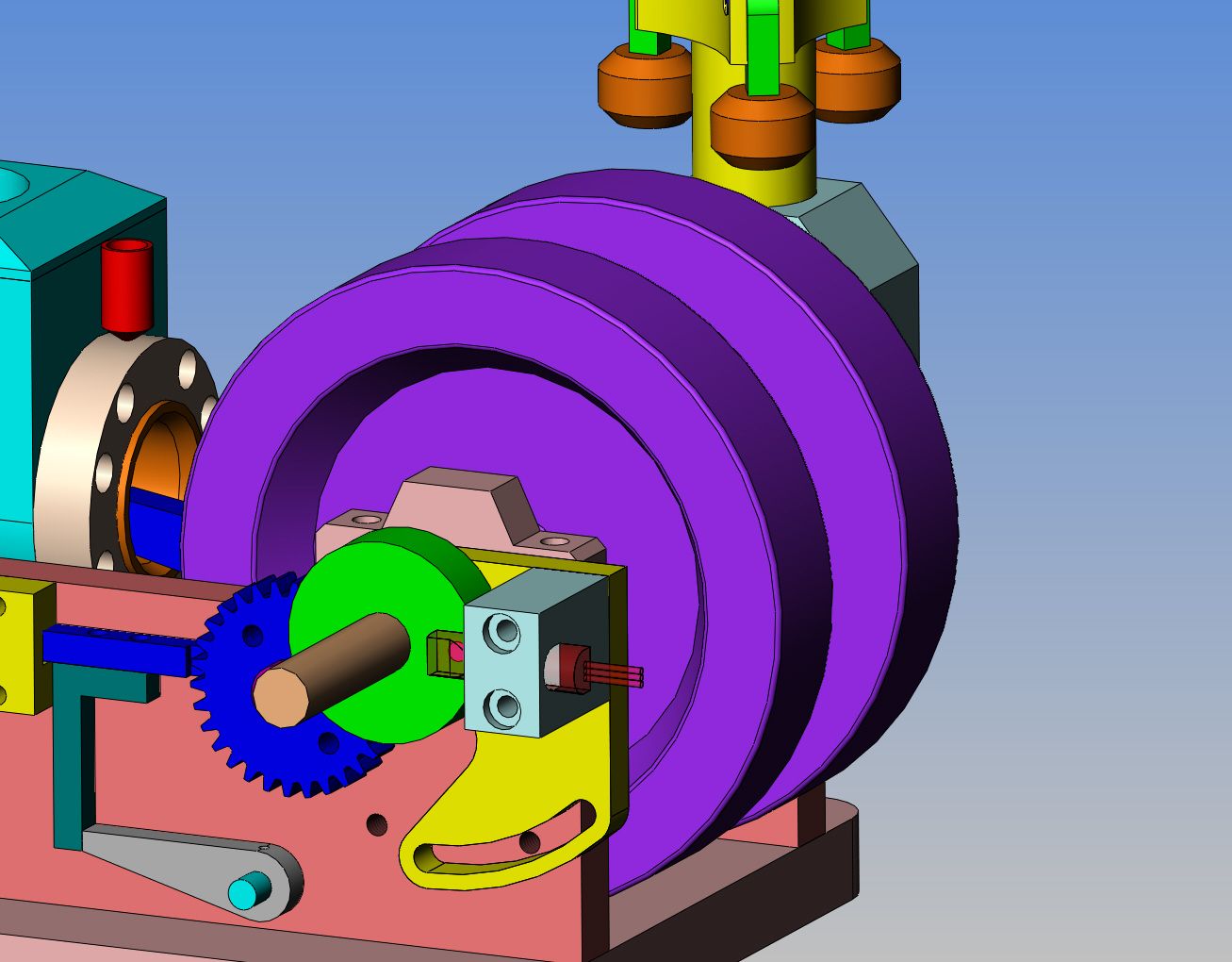
This is not intended as something that others who are building my engine should make. It is what I intend to do to mount the Hall effect switch and magnet on my engine for the cdi ignition. First, the ignition points, mounting bracket bracket and ignition cam are removed. The ignition cam is replaced with a 1.25" dia. x 3/8" thick aluminum disc with the 1/8" diameter x 1/8" long magnet set into the face with Loctite. The Hall effect switch is supplied mounted in a D-tube. The D-tube is epoxied into the light blue aluminum bracket. The light blue aluminum bracket is bolted to the yellow aluminum bracket, which has a round "register" in the far side that extends .050" into the counterbore in the sideplate and bearing cap, and a .400 clearance hole for the crankshaft to pass through. The curved slot is centered on the crankshaft and lines up with one of the existing #8 tapped holes in the sideplate which previously held the points bracket in place. The D-tube clears the magnet in the disc by about .020". The yellow aluminum plate can be rotated 20 degrees right or left to advance or retard the timing while the engine is running, by loosening the one #8 bolt off a bit. The aluminum disc with the magnet will have one set screw to hold its position on the crankshaft, and this will allow the initial "rough" ignition timing.

Last edited:
canadianhorsepower
Well-Known Member
- Joined
- Oct 22, 2011
- Messages
- 1,671
- Reaction score
- 324
be careful
were your magnet will be in your green will determine
your dwell diff RPM diff Dwell
were your magnet will be in your green will determine
your dwell diff RPM diff Dwell
- Joined
- May 27, 2010
- Messages
- 2,999
- Reaction score
- 1,171
Hi Brian & Pat,
Mine should have arrived by the time I get home from Thailand. Will be another experience.
Musket carry soldier trying out latest Gatling Gun.Will be fun.
Mine should have arrived by the time I get home from Thailand. Will be another experience.
Musket carry soldier trying out latest Gatling Gun.Will be fun.
Luc--If I've done this right, the following is copied from the set-up brochure that I got with my CDI. Notice point #9 about 'dwell" angle". Truthfully, I had to google "dwell angle" to see what it was. It is explained as " The amount of time (measured by the degree of rotation of the distributor cam) the contact points open on a points type ignition system".
CDI SET UP
1. Insulate the HallSensor from the magnet face
2. InsulateMagnet/Magnets
3. Magnet gap is notvery important
4. Magnet size isnot extremely important
5. FACT – Ifthe sensor triggers by turning over by hand it will see it at maximum speed.The maximum speed for the CDI is not the sensor and or magnet but the finitetime required to charge the capacitor.
6. Hall Sensor face and South Pole of magnet –can also be triggered from back side with North Pole
7. Good grounding toengine base is important
8. Firing CDIwithout spark plug attached can damage Hall Sensors
9. CDI systems donot have dwell angles
10. White wire islogic high
11. Points can beused that are normally closed
12. CDI can be triggered in several ways
13. Hall sensors are integrated circuits and arestatic sensitive
14. Wide voltage range – 3.8 to 6 volts DC
15. Compatible with all battery types
16. Low current draw
17. Black wire is always ground – excluding sparkplug wire
18. Red wire is always battery plus voltage
19. White wire istrigger signal wire for CDI
20. Do not mount CDIrigid to frame or base – my choice is Loctite Stick “N” seal or foam top andbottom if mounting inside a box. CDI should not bounce around or be able tovibrate excessively.
21. Naphtha is thebest solvent to use with Stick “N” Seal
Last edited:
canadianhorsepower
Well-Known Member
- Joined
- Oct 22, 2011
- Messages
- 1,671
- Reaction score
- 324
Brian ----- good luck
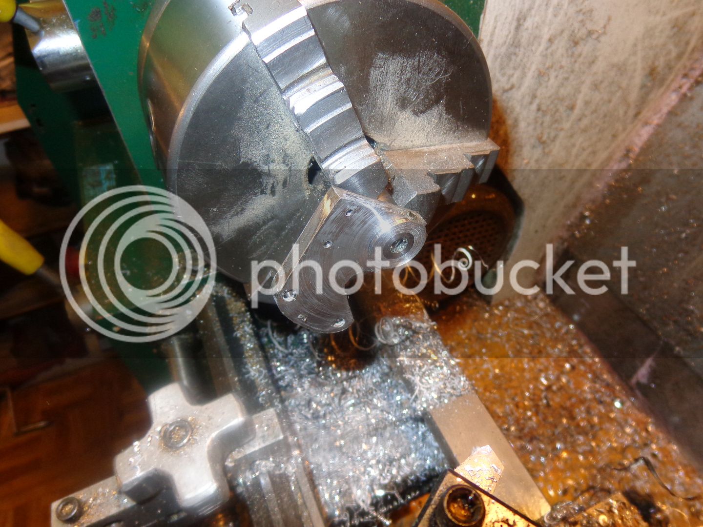
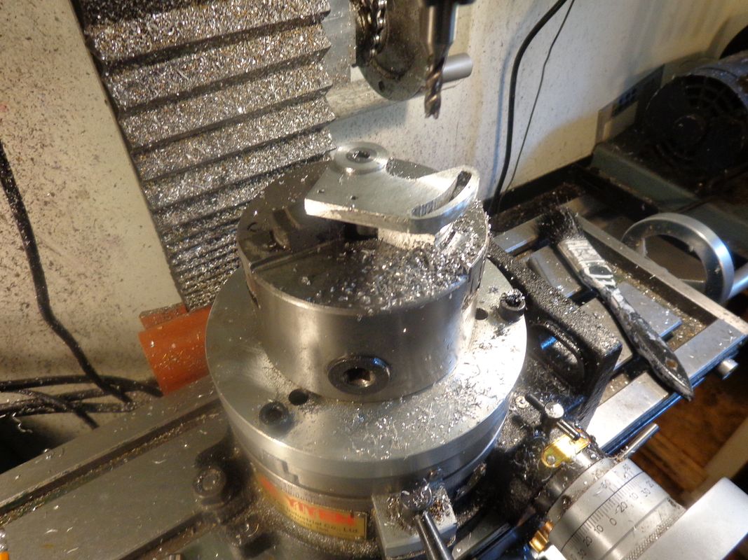
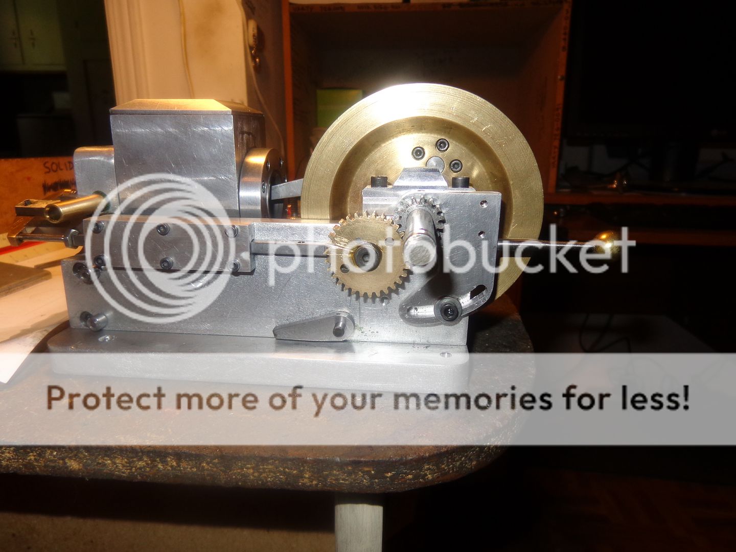
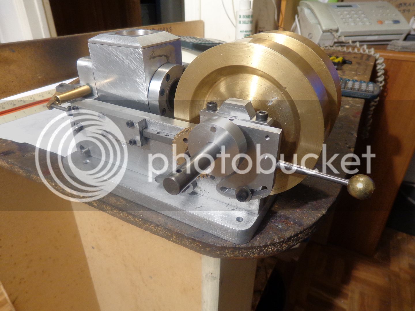
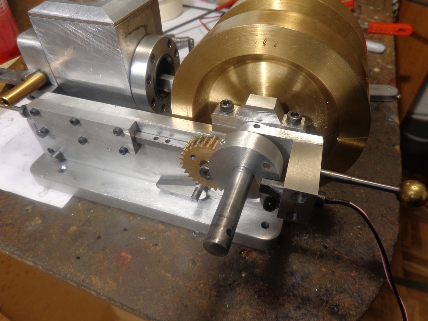
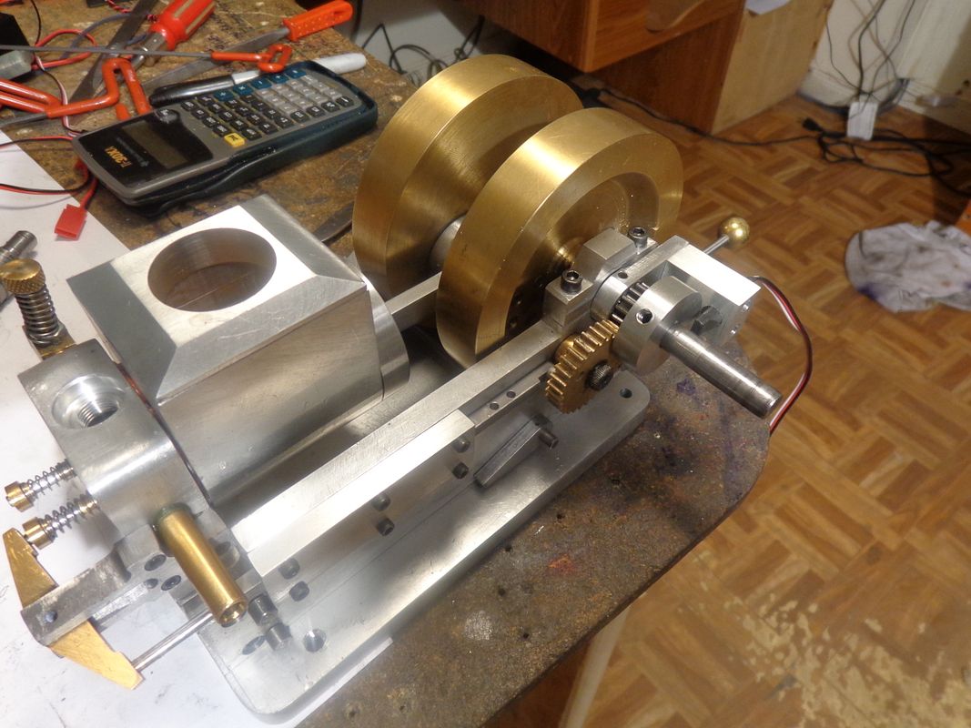
So what did I do today?? Made the first bracket to mount the Hall effect sensor for my CDI. This is the main bracket which bolts to the side of the engine and is adjustable about 20 degrees in either direction when the engine is running. In the solid model, it is the yellow coloured bracket. I had a handle left over from something else that didn't work out, so I mounted it on the new bracket. There are a couple of interesting set-up shots for what is basically a flat plate with a round boss on one side. I roughed out the plate, put in the tapped holes and cut the major contours, then drilled and reamed a 7/16" hole. (This is a clearance hole that the 3/8" crankshaft runs thru the center of.) I made up a short 7/16" stub arbor, mounted it in the 7/16" hole and cross drilled it for a 1/8" steel dowel. This gave me something to hold onto with my 3 jaw lathe chuck, and you can see it mounted and mostly turned in the first picture. Then it was over to the rotary table to finish off the areas on the boss that I couldn't do on the lathe and to put the curved slot in it. The third shot shows the plate mounted on the engine, complete with handle. Tomorrow I will build the aluminum disc with the magnet mounted in it and the piece which the Hall effect sensor D-tube epoxies into (which bolts to the plate I made today.


Last edited:
I had an attack of "Just one more partitis", so I made the aluminum disc and Loctited the magnet into it.--Funny thing about the magnet---The south pole is supposed to face the Hall effect switch.---Roy made it easy for me, and painted the south pole of the magnet black.---But the black rubs off REAL EASY!!! Damn, I hope I've got that magnet in there the right way!!!---And if you were wondering---There is about .030" clearance between the other side of that aluminum disc and the face of the gears.

Lord help us now!!!-I've passed the point of no return!!! The last bracket is made and installed, the D-Tube with the Hall effect switch is epoxied into place. All that's left is to wire everything up. If the gap between the D-tub and the magnet looks like a bit too much, I planned it that way. The aluminum disc which just clears the gears by 0.030" is only held in place by one #10-40 set screw. I can loosen it of and slide it out closer to the D-tube if I need to. I figured it was safer to do it that way rather than hit a target of .020" gap between the magnet and Hall effect D-tube and then run out of room.---Brian


canadianhorsepower
Well-Known Member
- Joined
- Oct 22, 2011
- Messages
- 1,671
- Reaction score
- 324
hey Brian--- How is your timing going to be change if your rotating
the hall sensor itself. ??
Just using the magnet strength signal??
look good
the hall sensor itself. ??
Just using the magnet strength signal??
look good
Luc --that bracket which holds the hall effect sensor rotates about the centerline of the crankshaft. It can rotate 20 degrees clockwise or counter clockwise from the position shown. Since it rotates around the same center as the crankshaft, that will position it ahead of or behind the magnet which rotates about the center of the crankshaft also. I sent you the ball-turner this morning.
Similar threads
- Replies
- 28
- Views
- 4K
- Replies
- 27
- Views
- 3K
- Replies
- 61
- Views
- 8K


