Minilathe improvement

Home Model Engine Machinist Forum

Help Support Home Model Engine Machinist Forum:

This site may earn a commission from merchant affiliate links, including eBay, Amazon, and others.

cfellows

Well-Known Member
Project of the Month Winner
Joined
Aug 25, 2007
Messages
3,890
Reaction score
715
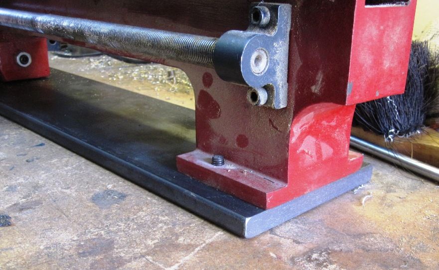
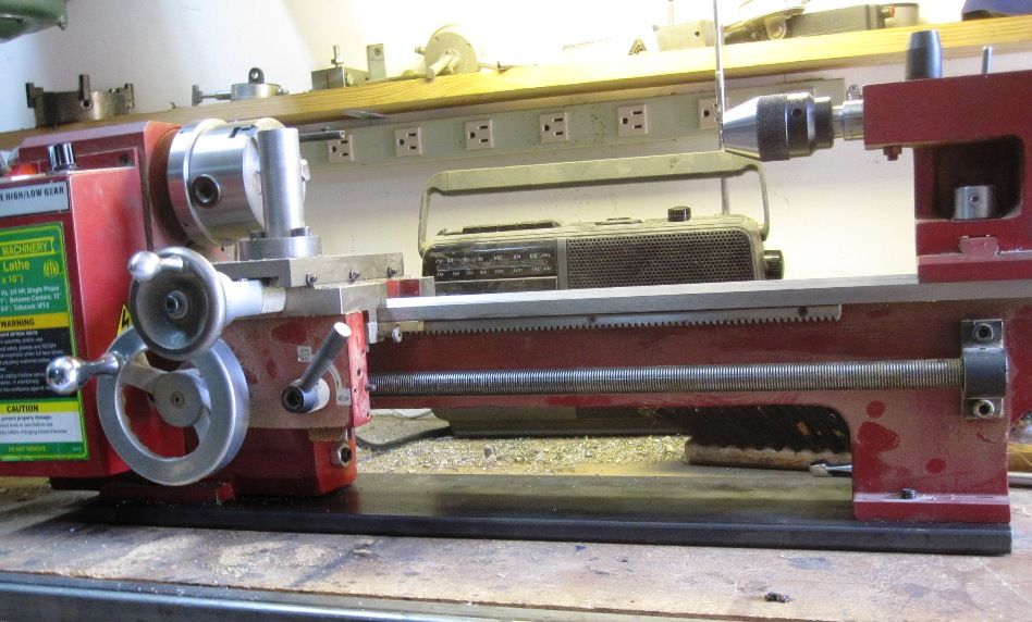
I've done a number of things to my minilathe to improve it. It's basically a very utilitarian machine and can do very nice work. I had previously converted the 3-jaw chuck to an adjust-tru version so I could bring the run-out down to virtually zero. I've used the lathe like this for over a year but recently noticed that the lathe was cutting tapers on longer work. Using the Rollie's Dad method, I discovered the taper to be about a .002" every 3 inches of travel. Up to now, the lathe was simply sitting on the workbench, not bolted down. So, I bought a piece of 5" x 1/2" hot rolled steel which I cut down to 24" in length for my 14" bed. I drilled holes in the steel plate to match the holes in the lathe feet.

IMG_2807_zps74ac83d7.jpg


IMG_2808_zps65742107.jpg


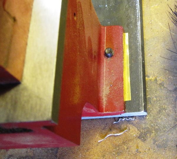
After bolting the lathe securely to the plate, I again checked the taper and, while better, it was still off by about .003" over 8" of travel. I loosened the two bolts on the tailstock end and used a feeler gauge to determine the right amount of shimming to eliminate the taper. I settled on a piece of brass shim stock about .015" thick to bring the taper down to near zero over 8" of travel.

IMG_2809_zps25a8ff22.jpg


Haven't tried it yet, but I'm expecting to get more rigidity now which will lead to less chatter and more consistency in turning work pieces.

Chuck
 
Good thinking!

The biggest piece of steel you can find bolted under that thing will certainly help alot. For further improvement, one could also take a queue that was popular in the old days of machine tools where steel or iron was embedded in concrete. A wooden box could be made, piece of steel plate selected, and studs could be set into the cement. Pour the cement up the sides of the plate, but leave the top bare. When it dries, torque the nuts on the studs, and bolt in and level out the lathe.
 
Have you checked to make sure the spindle lines up with the tailstock? Use two centers and make sure they touch each other on the point.
 
Have you checked to make sure the spindle lines up with the tailstock? Use two centers and make sure they touch each other on the point.

No, I expect that will be the next thing to do. I don't turn things between centers on this lathe, but I do use the tailstock to hold drills for drilling work held on the spindle.

Chuck
 
Yeah I repainted my lathe a few years back and made the mistake of taking the head off the bed. And spent quite a bit of time getting rid of the taper, on my 9x19 lathe there are 4 adjusting screws for the head and if I remember right the mini lathe is similar.

I found the best way to tram it back in was to mount a magnetic indicator on the saddle with a long straight 3/4 inch surface ground mold pin sticking out the chuck. Once that was squared up then I mounted centers in the chuck and tailstock and got them dead on. My tailstock has an adjustment and I don't remember if the mini lathe has it too.
 
Chuck this video intrigues me as it features the same lathe I have

[ame]http://www.youtube.com/watch?v=Uk2Q9H4RLp8[/ame]

The guy has clamped his lathe stand to the floor and is now achieving mirror like finishes. My lathe is much more stable now on its new stand but I am considering clamping it down to see if it makes any more difference.

I guess I also need to review the alignment of the bed too.
 
I think that we are looking at several problems. I doubt that mirror finishes have any relation to whether the lathe is bolted down or in twist or whatever. My point is that it has more to do with just how sharp the lathe tool is, how far it off the work, the type of material, the speed of the work, its diameter and so forth. If you think that if a hand held graver will cut quality watch and clock parts, you will have to agree.

As far as alignment is concerned, I think that people are wasting their time bringing up the two centres- the one on the spindle and the other on the tailstock. Clearly, it aligns the pair but it doesn't tell you whether the bed is in warp or the spindle and headstock are off to ways, the tailstock similarly or the saddle is playing silly buggers.

Frankly, there is no cheap and cheerful way. Who Rollie is - I haven't a clue. I do know who Schlesinger is and how a professional would set to and check your lathe. Initially, you have to chuck a set of spirit levels across the bed- up the lathe and at several places across. Once this holds fair you can move on to toying with the spindle/headstock- and clock it and do a cut of a test piece. Again, it is all in the books. Then you check the saddle to the face plate so that your tool will just face concave and so on. Then you check to see whether the poppet in the tailstock is not pointing in several directions but the one that it should.

I'm afraid that this is an indication- it is by no means exhaustive. Exhausting? Too true. Go back to Schlesinger or Connolly but NOT to Auntie Fanny or whoever has the flavour of the month as the village idiot.

You may wish to differ.
 
In the old South Bend documentation I've read, they recommended turning a shaft with two collars on either side. You take a very light finishing cut under power feed against both collars. If they are the same diameter then you are good to go.
 
In the old South Bend documentation I've read, they recommended turning a shaft with two collars on either side. You take a very light finishing cut under power feed against both collars. If they are the same diameter then you are good to go.

Actually, this is not. This, as I intimated earlier is part but no more.
I am merely re-iterating what is machine tool examination- and haven't gone into the realms of necessary corrections to put a machine into alignment.

I was fully aware of South Bend and indeed Myford when penning my considered reply.
Again, I strongly suspect that Edward Connelly wrote his tome( and it is a hefty one) on his experiences and conclusions with South Bend machinery.

All that has really happened in the intervening years is that Filled Epoxies etc such as Turcite, Devcon and whatever have become part of machine tool restoration. They add to Connolly, they don't alter what he advised.

In another similar forum, it would appear that the comments about the costs of metrology are discussed at some quite alarming depths.

Regards

Norman
 
I'm going to second Goldstar's comments, there's no point testing or adjusting *anything* until all twist is removed from the lathe bed and ways.
A good quality sensitive level is essential, as is a parallel or two for spanning V and flat beds - unless your machine has a T-slotted boring table, in which case you already have a decent reference surface. I'm fortunate enough to have a flat boring table and a vintage clinometer accurate (and calibrated) to a few seconds of angle, roughly 0.0003" in a foot (yes, three tenths of a thou"), which is adequate and then some... It has the advantage of a micrometer dial to set the vial level, so can compare non-level surfaces: the ways *don't* need to be level, but *do* need to be at the same tilt at both ends!
Even a small amount of twist will cause taper in the work, I've seen more than 10 thou" over 4" taken out by a single shim under a cabinet foot, unfortunately the hobby lathe importers don't stress this in the chinglish handbooks and I've made quite a few calls to "inaccurate" new lathes that were fine *once levelled*. Once the twist's eliminated, leave for a few days to settle and recheck, if all's good you can then look at the rest of the alignment.

Chuck, that's a useful improvement for a reasonable cost - a hefty box section would work well, too, but what you've done has effectively increased the depth of.the bed casting significantly, and the stiffness is more.that a linear.function (square? cube?) of.the depth - nice :)
 
Well, said, sir! Sometime back, I wrote up in Model Engineer a cheap and cheerful 'restoration' of a very worn Myford ML7 which a friend had bought- in ignorance. It wasn't a high falutin one but merely removed the lathe out of a class where it was turning bananas and sort of got to 'a half thous or thereabouts'
The ML7 is a flatbed and therefore can have the wear which occurs about 6" from the spindle/chuck removed by Blancharding. This is a cheap swipe across the top surface of the bed with a grinder but does not address the shears or much else. However, it does provide- if one thinks about it- a reference of reasonable flatness on which to do other improvements. Initially, I got a cheap bit rectangular steel which would scrape to look at the shears and carefully scrape the all important number 1 shear. It didn't take long and I was able to tackle the underneath of the saddle which had enough grooves in it to imitate a Churchill tank going over a metal cattle grid. I had a little battered surface grinder at that time, but earlier I had handscraped my earlier Super 7B.
Really, there is nothing new or difficult in getting a lathe 'in a decent shape' to make most models. I used an old file as a scraper, a bit of blue and used a set of cheap joiners spirit levels. I even used these high tech strips of cigarette papers.
No, it addresses an improvement which for most of us, makes a huge difference but it doesn't create an instrument lathe.

The cost? I think that it was about £30-- and a set of very inky fingers.
 
...
Chuck, that's a useful improvement for a reasonable cost - a hefty box section would work well, too, but what you've done has effectively increased the depth of.the bed casting significantly, and the stiffness is more.that a linear.function (square? cube?) of.the depth - nice :)

Oftentimes it's the low hanging fruit that is easiest to acquire and is usually the sweetest.
 
Back
Top