Anybody guess what this is going to be???

Home Model Engine Machinist Forum

Help Support Home Model Engine Machinist Forum:

This site may earn a commission from merchant affiliate links, including eBay, Amazon, and others.

cfellows

Well-Known Member
Project of the Month Winner
Joined
Aug 25, 2007
Messages
3,890
Reaction score
715
_IGP2439.JPG


Here's a hint...

_IGP2441.JPG


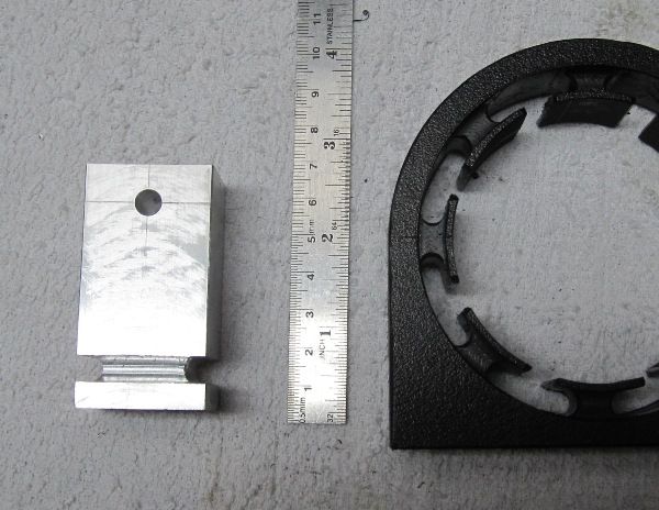
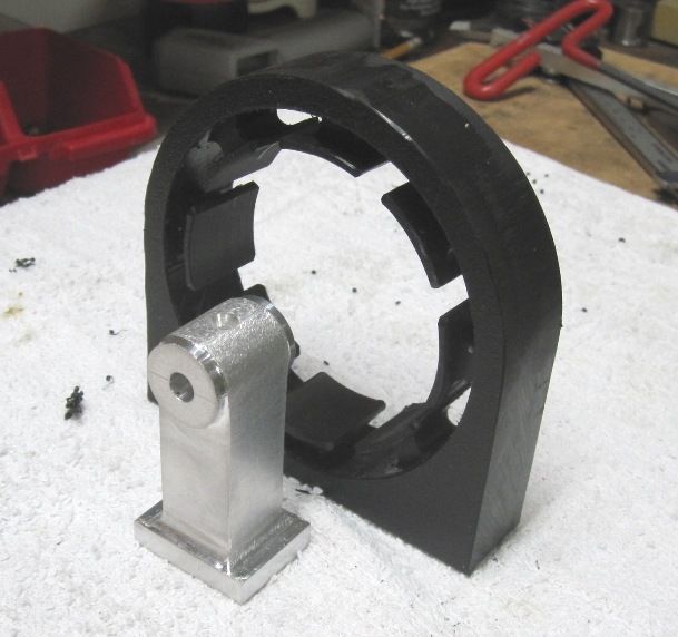
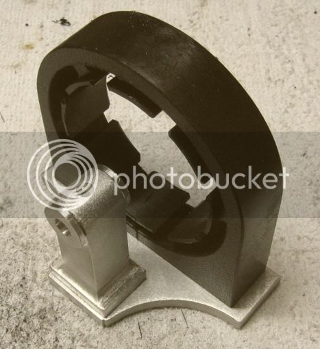
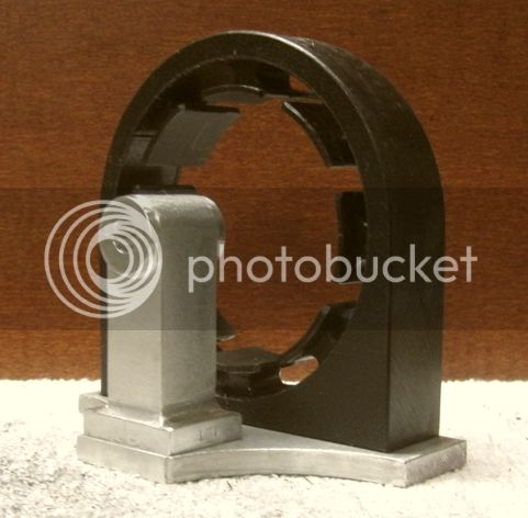
It's going to be an air core dynamo, obviously. I started with a 4" square piece of 1" thick, HDPE (High Density Polyethylene). Also sometimes called Seaboard.

_IGP2433.JPG


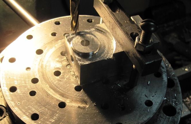
It's used a lot in the boating industry. It's pretty rigid, but does have some give to it. Machines like a dream. I decided to make the core out of plastic since it won't put out a lot of power and, more importantly, the Fairbanks compressed air engine should have enough power to run it and light up a few LED's. Here I'm drilling a 1/4" hole in the center
.
_IGP2435.JPG


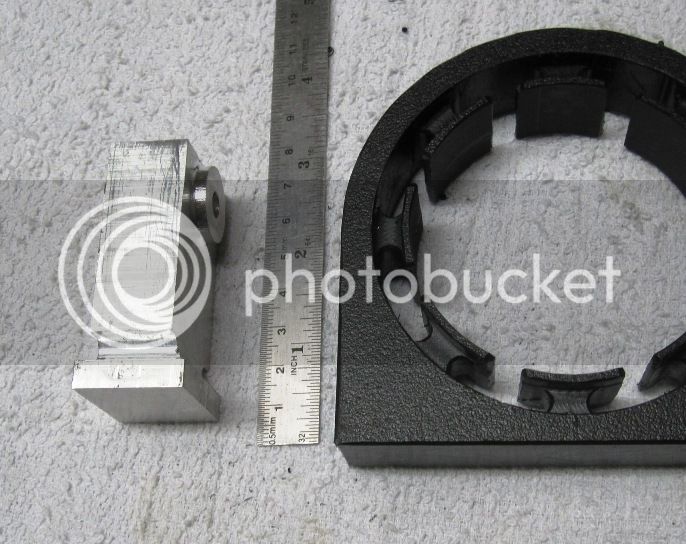
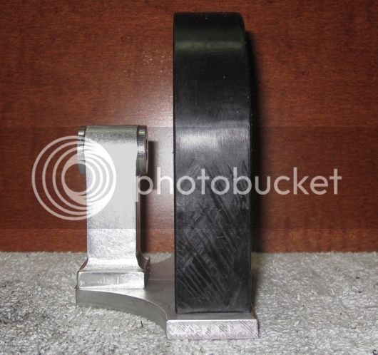
Next I cut circular grooves on both sides. These grooves will form the coil winding channel.

_IGP2436.JPG


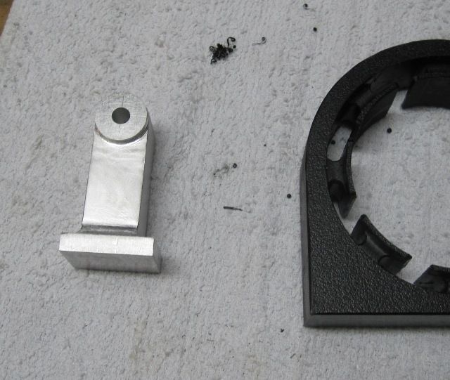
I changed rotary tables and started whittling away everything that didn't look like a dynamo core.

_IGP2438.JPG


This will be a single phase AC alternator. I used a lot of the information provided by Manfred Albert, here:

http://www.homemodelenginemachinist.com/f23/dynamo-build-castings-17756/

I'll be using #24 magnet wire, hoping to get 60 or 70 turns per coil. They will all be hooked in series. Not all sure what kind of voltage and current I'll get out of this thing, but since LED's will run on about 3 volts or less, I think it will be sufficient.

Chuck
 
generator? yup should have read before I relpied
 
You didn't even give us a chance to guess! I knew it was an alternator as soon as I saw the first pic. I really dig homemade alternators.

I expect you'll get enough volts and amps out of it to power small incandescent bulbs... LED's for sure.

You may know this, but in case you don't, I'll ramble a bit:

Voltage will primarily be a function of RPM. When you run LED's you of course need a resistor in series, however, if you plan to vary the engine speed during operation, this could be a problem and if too high could burn up the LED. You may need to use something like a 7805 voltage regulator supplied by a bridge rectifier and a filter capacitor... along with a current limiting resistor for the LED. There are formulas to calculate the correct resistor value, but the easy way is to cheat and go to http://ledcalc.com/ to calculate the ohms necessary.

Thanks, I hadn't really thought about the fact that LED's can be a little persnickety about voltage and current. Hopefully I'll get enough juice out of it to run one or more incandescent bulbs.

I started work on the outboard stand for the armature today. I started with a 1" x 1.25" x 3" piece of aluminum. In this first picture I've drilled the pilot hole for the armature shaft and went all the way around the base with a 1/4" ball nose end mill.

IMG_2797_zps8574177e.jpg


Here I'm using an end mill and my rotary table to start shaping the front and back.

IMG_2798_zpsd1b84853.jpg


Finished rough cutting the front (or back :-\).

IMG_2799_zps98b89628.jpg


And here's a couple of pictures after all the shaping and filing is done.

IMG_2800_zps97f7f4c4.jpg


The finish, such as it is, was made with my random orbital sander.
IMG_2801_zpsc8c36147.jpg


Chuck
 
The incandescent bulb(s) would be neat because you would be able to see the brightness change with engine RPM.

That being said, don't let a voltage regulator scare you off from using LED's. It's a very simple circuit that anybody with a soldering iron can pull off easily. All the parts, the bridge rectifier, 7805 regulator, capacitors, resistors, and LED's will be available at Radio Shack relatively inexpensively. You could build a wooden base for the engine and use brass brads driven to the underside of the wood as solder terminals.

You can put multiple LED's wired in parallel, just give each it's own resistor of the same value. The LED packaging will have its specifications which you can plug into that resistor calculator I linked to earlier.

I'm keeping an eye on the thread, so let me know if you have questions.

Are you planning on making a street light or some type of fixture to put the bulbs/LED in?

(Your circuit wouldn't have the transformer, the alternator output would go right to the bridge rectifier.)

LfaYEJt.png


8P0YnET.png
 
Thanks, Moya, the circuit diagram will be useful. I hadn't really thought about how I would mount and display the lights.

I had considered making a realistic looking but non functional dynamo with a hall effect circuit to determine RPM. I would input that to an Arduino Nano which in turn would power one or more LED's. The Arduino would change the brightness of the LED's based on the RPM of the engine/dynamo.

However, at this point I'm more interested in seeing if I can make a functioning, easy to build, low power dynamo. I think it might be of interest to some of the other engine modelers.

Chuck
 
With all due respect to Moya's regulator idea, I would instead simply measure the generated open-circuit voltage of the finished generator at max rpm, then calculate the correct dropping resistor for that max voltage plus a little extra.
If you use a high brightness LED, you will still get a decent light output at low rpm.
If you then increase the revs the LED will get brighter but you won't smoke it.

This will make the LED behave like an incandescent in that the brightness will vary with voltage/rpm, which is probably preferable in a scale application.
A decent warm-white high brightness LED would emulate an incandescent quite well. Except ofcourse its colour won't change as markedly as an incandescent will at low power.
Or you could use an incandescent ;)

Another thing to consider, is if the generator voltage ends up being very low, the regulator needs an overhead of approx 1.25 to 3v and there may not be enough left over to bias the LED.
 
Last edited:
/// has very good advice too. :)

Really, the best direction to go down will be decided once you get a volt meter on there, and an ammeter with a load attached.

I'm curious how you are going to be wiring the coils. Were you planning on wiring them all up in series, or were you going to be making a 2 phase AC configuration?

The armature will have 16 bar magnets arranged with alternate N and S poles facing outward. The coils will all be hooked in series.

Thx..
Chuck
 
Got the stator frame and outboard armature support mounted on a common base. Next I'll start on the armature and armature shaft. I need to order the magnets. I'll need 16, 1" x 3/8" x 1/8" bar magnets with the poles on the large flat face. Or I could use 1" x 1/4" x 1/4 with the poles on the long sides. This would allow a bit more space between the magnets.

IMG_2806_zps22cd0720.jpg


IMG_2805_zps4c8caa0e.jpg


IMG_2803_zps59bf90bd.jpg


I want to get the armature assembly finished before I start winding the coils so I can experiment a little with different numbers of turns in the coils.

Chuck
 
Another thing to consider, is if the generator voltage ends up being very low, the regulator needs an overhead of approx 1.25 to 3v and there may not be enough left over to bias the LED.

This is why I usually stay away from linear regulators like 7805's. They work very well, but they are basically a resistor that keeps the output constant. They waste a lot of energy.

If you want to be ultra efficient, you can go with a simple buck-boost circuit. These are a bit more challenging and more expensive to produce. Often the IC's are in surface mount packages with very small, close together legs that are difficult to solder to.

Something like this:

http://www.linear.com/product/LTC3402

These are often called "joule thieves" as they can sap every last bit of power out of batteries and low voltage sources (In this design, you would have to play with R2 to get the desired output voltage. Note the efficiency, 97% at 100ma!). 5v is awfully bright for an LED, and even a 3.3v LED would be pretty bright, but would not require any changes in the LTC3402 schematic Linear so kindly provided us. An LED like this:

http://www.radioshack.com/product/index.jsp?productId=3060980

Now, assuming the generator puts out 1.5V, and just 1 of these LED's draw 25ma, thats about 0.0825W. The LTC3402 is about 70% efficient at this low of a load, so you are going to see a draw of about 71.5ma at 1.5V, or about 0.10725W.

So it might be in your best interest to run 2 or even 4 of those LED's to get that LTC3402 right in it's sweet spot efficiency wise. Of course, we don't know how much voltage that generator will put out yet, so this is all hypothetical.
 
I would put a string of LED's on it and forgo the resistors and voltage regulator. You might not realize that you are building the electrical equivalent of a bicycle wheel hub dynamo. You can use simple electronic circuits once you figure out the current/voltage output of your dynamo once you test it. Once you have that information you can use the same circuits available here to build a really impressive LED lighting system. I designed this system for my own use on my bicycle. It allows me to recharge any device that can be powered and/or recharged by plunging it into a USB computer port. The rechargeable batteries act as voltage regulators and provide power (when fully charged) to power any device that plugs into a USB port. The switch in the circuit allows switching to my LED headlight when required if riding at night. Here are a few pictures of me and my bike before I set off on a 218 mile tour.

This is a picture of my LED headlight made of Bamboo.
dsc00058.jpg

Here is a picture of my dynamo that powers that headlight or the USB power system.
index0.jpg


Here I am starting on my Bike Touring Journey.
index2.jpg
 
If you want to increase the power producing potential of your plastic cored genny, you could simply imbed some short steel rod pieces in each core center. Any small amount of soft steel would dramatically increase the induction potential of those coils and you can always go back and add them later if you decide more power is needed. The steel could even be hidden by gluing some round pieces of ABS plastic over top of the hole they are pushed in.

Just a suggestion. Been thinking of various versions of a small genny build myself.

Oh, and I've used this vendor for magnets many times before.
Here is their offering in the size you mentioned.
http://www.kjmagnetics.com/proddetail.asp?prod=BX062
 
Last edited:
Are you going to wind the stator by hand? That can be a real pain.
The salient poles could be desighed to separate and bolted on. The salient poles may have a round section to make the winding easier.
A shallow slot (difficult to machine) or a simple pin could be used to align each pole.

I love alternators, I did save a bundle of tomato cans lids planning to glue up a laminated block for a 3 Phase alternator but got sidetracked with other projects and settled for the dynamo kit that is available on line.

Hey, Mauro, good to hear from you. Missed you at this months meeting at Rudy's! Yes, I'll be winding the stator by hand. I made a little tool out of brass tubing that will make it go a lot faster. The windings won't be pretty, but I think they'll be tight and effective.

Chuck
 
If you want to increase the power producing potential of your plastic cored genny, you could simply imbed some short steel rod pieces in each core center. Any small amount of soft steel would dramatically increase the induction potential of those coils and you can always go back and add them later if you decide more power is needed. The steel could even be hidden by gluing some round pieces of ABS plastic over top of the hole they are pushed in.

Just a suggestion. Been thinking of various versions of a small genny build myself.

Oh, and I've used this vendor for magnets many times before.
Here is their offering in the size you mentioned.
http://www.kjmagnetics.com/proddetail.asp?prod=BX062

Yeah, I had already thought of inserting steel in the plastic cores if need be, but I don't think I'll need it. Actually, I just ordered 16 bar magnets from the KJMagnetics. They had a huge selection of different sizes and their prices weren't bad.

Chuck
 
I still think that, even using the 16 magnets, you should arrange them to make the same amount of poles as the stator. You could experiment both ways but the best results will be with 8 pole stator and 8 pole rotor.
 
best results will be with 8 pole stator and 8 pole rotor.

I am no alternator expert but I think 16 poles (8 pairs) will produce "in theory" twice the voltage at twice the frequency versus an 8 pole (4pairs) configuration. One one hand you get more voltage on the other hand core losses wil almost quadrupled. Having a solid core keeping the frequency low would be an advantage.

With model alternators the typical problem is getting enough voltage at reasonable RPM.
Keep the gap (rotor stator clearence at minimum.
Use small wire and many turns, wires around #30 gauge are just right to wind not too fragile not too stiff, and still can carry 0.5A in an open frame environment.
 
As a bit of a lazy so and so when it comes to electrickery, I like the Zener diode system as used in Triumph and other motorcycles... An infinite supply of wiring diagrams and ideas that work efficiently are always available on the custom and classic motorcycle forums.
 
Back
Top