Clutch---Again!!!

Home Model Engine Machinist Forum

Help Support Home Model Engine Machinist Forum:

This site may earn a commission from merchant affiliate links, including eBay, Amazon, and others.

Brian Rupnow

Design Engineer
Project of the Month Winner
Joined
May 23, 2008
Messages
14,971
Reaction score
8,253
Location
Barrie, Ontario, Canada
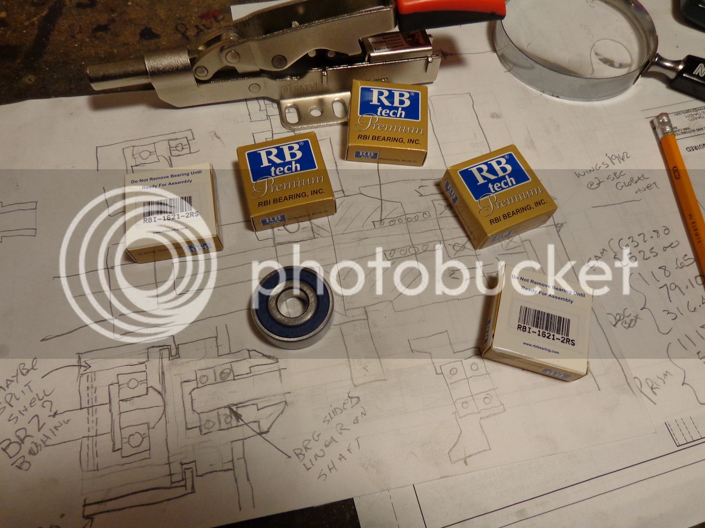
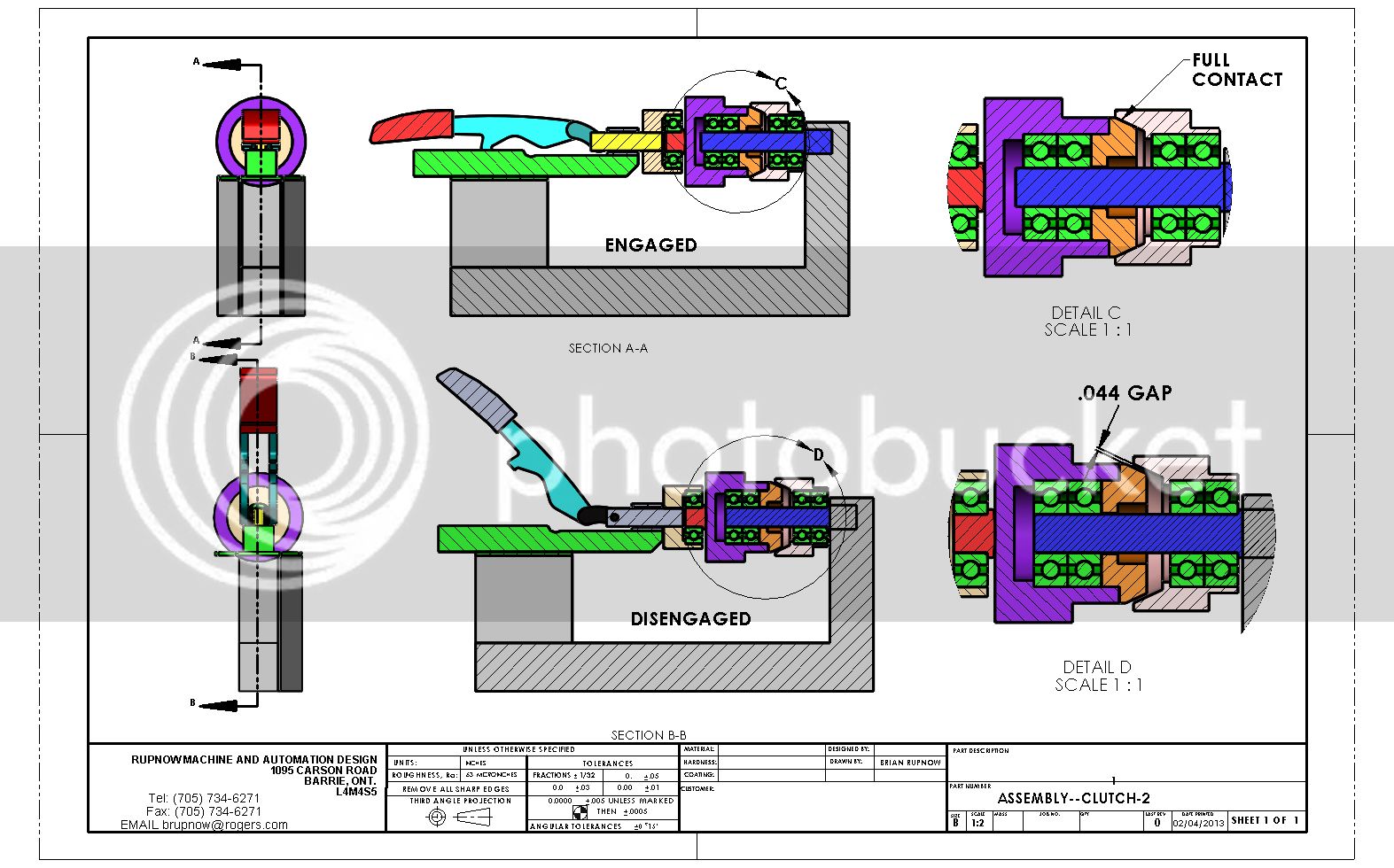
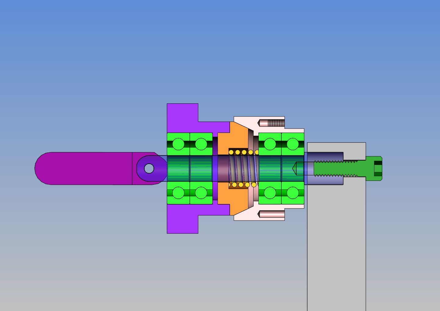
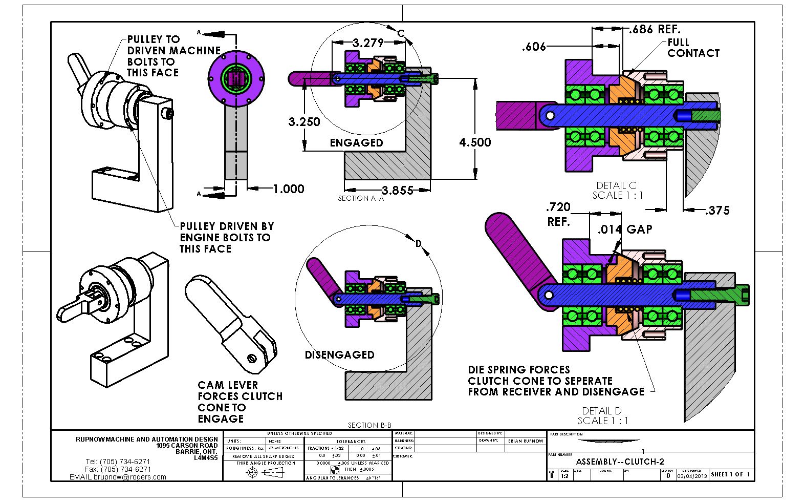
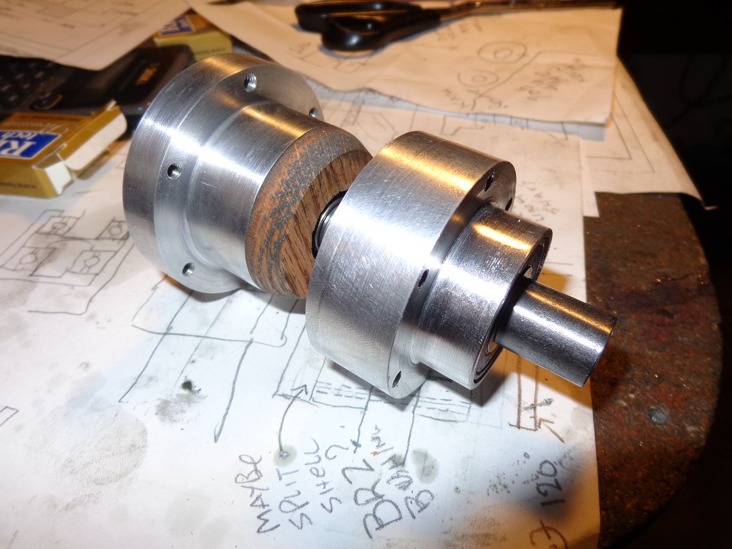
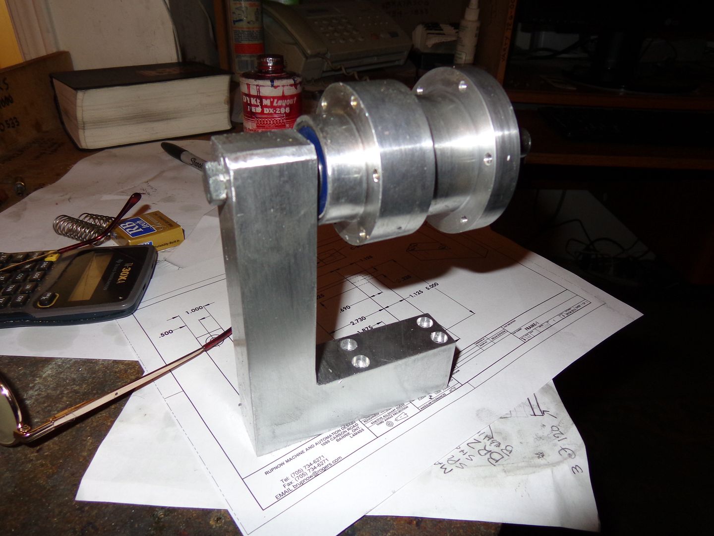
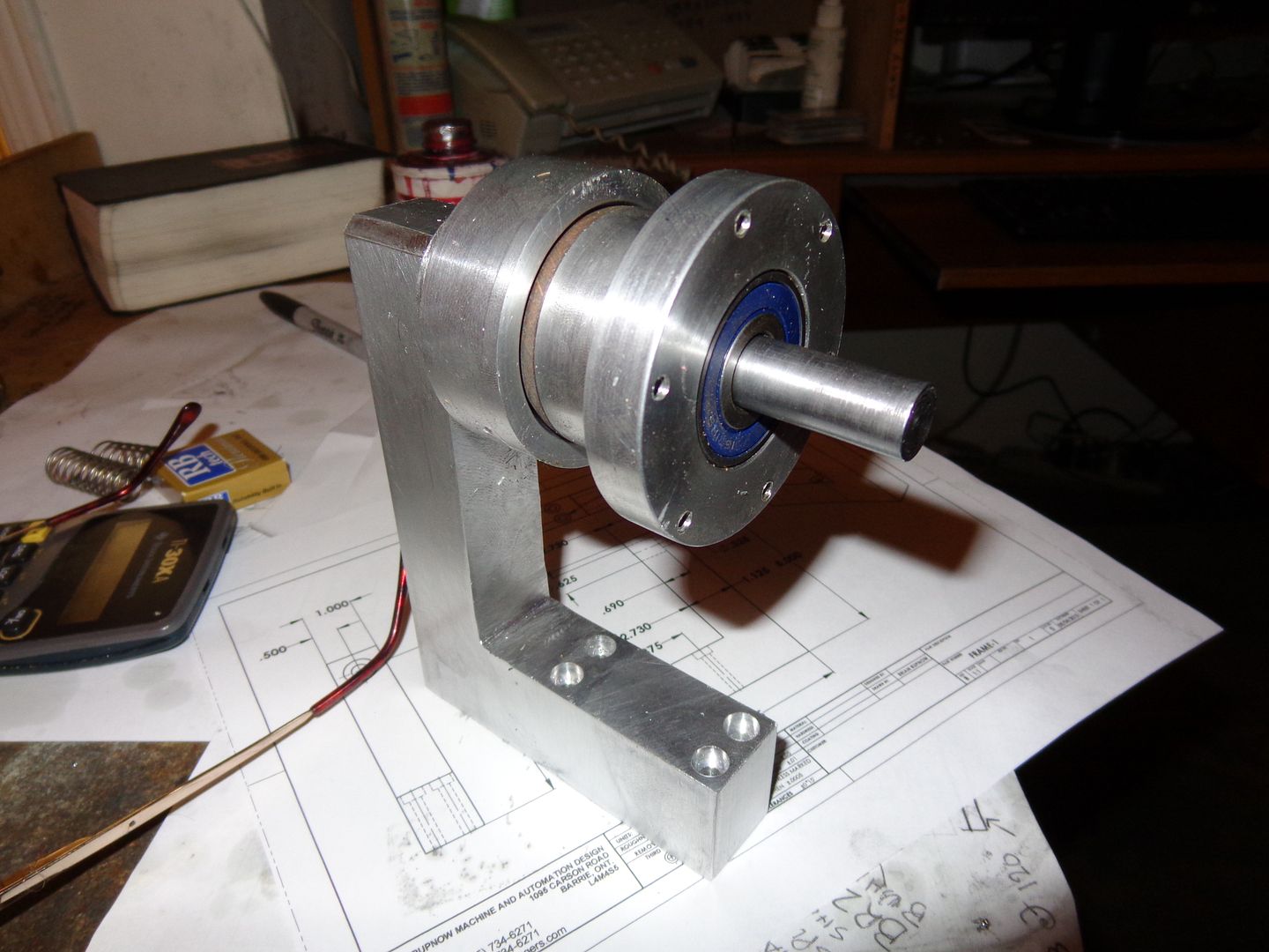
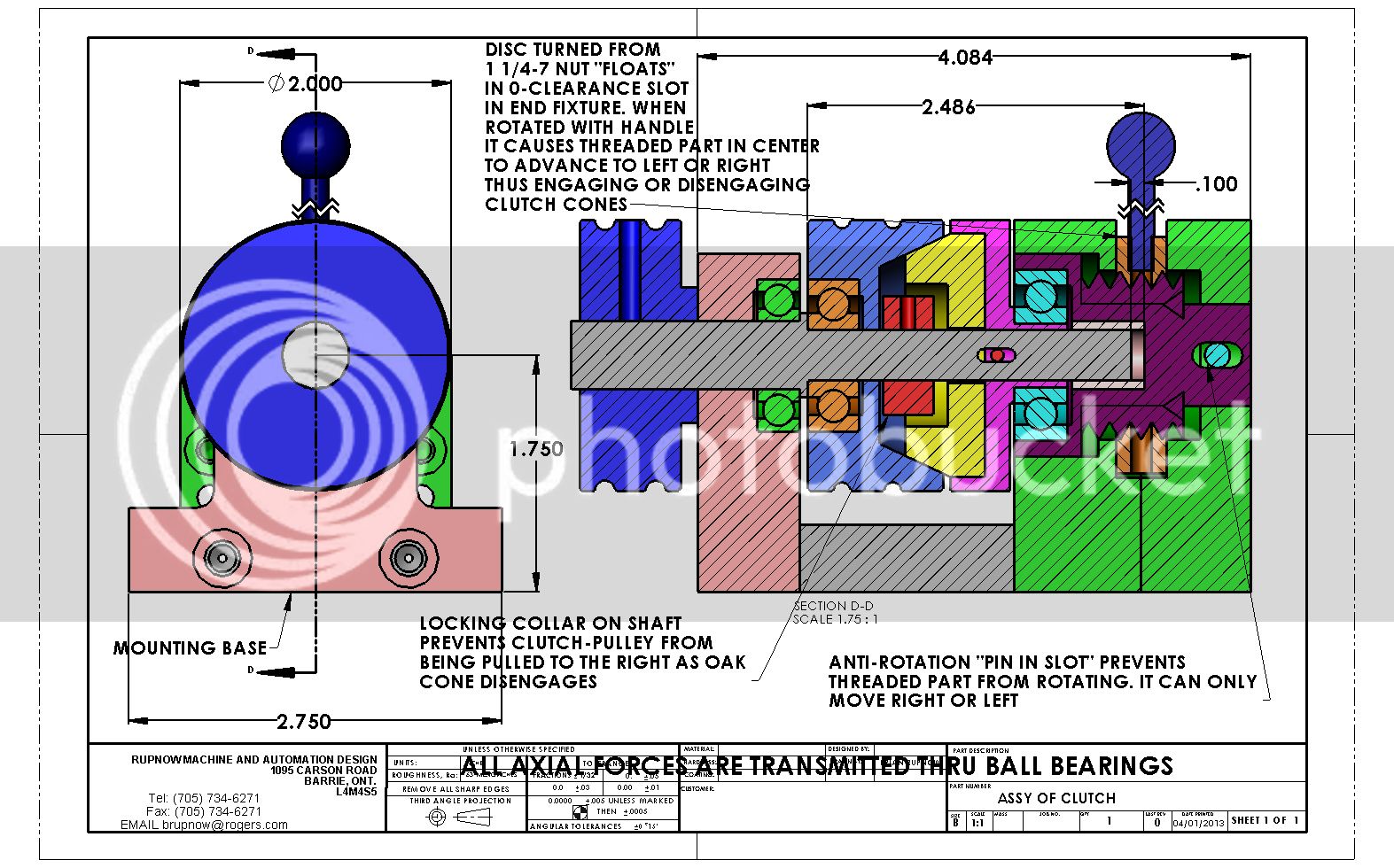
Earlier this winter I designed and built a clutch, to use between one of my i.c. engines and a model sawmill I designed and built. Unfortunately, although the clutch worked, it had issues with internal binding which robbed a lot of the power, to the extent that my small engines couldn't cope with it. The design you see posted here is the design that I built and had the problems with. I am going for a total redesign, which although it will still be a cone type clutch with a wooden cone, the actuator will be a purchased Destaco type "push-pull" clamp.
ASSYOFCLUTCH_zpsc1e07c93.jpg
 
Last edited:
The first clutch I made was made with what I had laying around. This time, I'm getting more serious. I'm actually spending some money. I have bought a Destaco style "push/pull" clamp, and 6 bearings (I may not use them all) from Canadian Bearings, a local supplier. The bearings are single row sealed ball bearings, 1/2" bore x 1 3/8" o.d. x 7/16" wide. Before anyone jumps on my back about using "thrust bearings", keep in mind that the engines this will be used with are micro horsepower. A normal ball bearing is well capable of withstanding any axial thrust loads they will see in the applications I have planned for them. The shaft will be supported at one end only, and the entire design will be more amenable to changing belts on than the previous design. I am still early in the planning stages of this clutch, as you will see by the sketches on the paper under the bearings. I don't recomend that anybody jump right in and start building this with me. I want to finish this one and "field try" it to avoid some glitch showing up "after the fact". I will post pictures and models as this develops, and a video of the field trial" when it is finished. I will also try and address any shortcomings that the previous design had, one of the big issues on the first clutch being the limited size and type of pulley used on it.----Brian
BEARINGSANDCLAMP001_zpsda5dea4c.jpg
 
This is uglier than original sin, but its a start. The pulleys are not shown yet. Neither is the die spring that forces the cone away from the receiver. However, I've been working 3 hours on it and thats enough for tonight.
ASSEMBLY--CLUTCH-2_zpscd62becb.jpg
 
Hi Brian,
My suggestion is to use an over centre style clutch, such as many
dozers and marine gbx's used.
Advantage being there is no axial load being applied to the mainshaft,
thus reducing to the angular thrust on your ball bearings to zero.
They are easy to make, and not hard to have air operated.
I have some sketches at home of one, but I wont be home for a day
or so.
try googling for a schematic of one.

Dave.
 
I like this design better. The Destaco clamp is gone. The base is much shorter. The clamp has been replaced by a cam type lever to engage the clutch, and a die spring mounted internally disengages the clutch. There is enough room to put a 6 1/2" outer diameter pulley on either hub. The belts can be assembled without taking anything apart. There are fewer bearings. the blue center shaft does not rotate. It is a stationary, cantilevered design. All axial forces are transmitted through the bearing balls.
ASSEMBLY--CLUTCH-2-blowup_zpse632ebbc.jpg

ASSEMBLY--CLUTCH-2_zpsb3c443f3.jpg


View attachment ASSEMBLY--CLUTCH-2.PDF
 
Last edited:
Brian

Are you going to have problems with the spring when clutch is disengaged with relative motion between fixed and moving parts.

Dave
 
Brian

Are you going to have problems with the spring when clutch is disengaged with relative motion between fixed and moving parts.

Dave
If I do this right, The spring will run out of compression after its first .040" of travel. I would hope it shoves the wooden cone back far enough to disengage, and then just lays in there without putting any force against the wooden cone.
 
Brian, I see a number of potential problems with your clutch design. The first one is the limited amount of surface area on the frictional faces of the cones. This would require a good deal of pressure to be placed on those two components in order to get a good drive and that pressure may increase the drag on the bearings causing significant losses in the drive train. Secondly, the spring will cause friction between the driven and non driven components with the clutch disengaged. Although it may be less of a problem, you may find that it is impossible to completely disengage the clutch, IE: some drag will remain between the driven and non driven components.

Have you considered using a multi-plate clutch similar to those found in a modern motorcycle?
 
You could still use the cantilevered shaft, except make it hollow and have a release rod running through. The release rod pushes outward on a spring loaded plate (on the driven side of the clutch preferably to eliminate idle drag) to disengage the clutch.
 
Trumpy---Thanks, but thats way too many parts for me.

Brian, you don't need to use that many plates in the clutch. One or two is all that is necessary for a clutch of the scale you would need.

I'm sure you could simplify it even further without losing it's effectiveness. the main thing to remember is that the friction plate has a much larger contact surface area than your current clutch, and that area is doubled because both sides of the plate are used. It also requires much less pressure in order to get the clutch in the locked up state.

Would it help if I told you that this type of clutch is also used in Top Fuel dragsters?
 
A multi plate clutch could be compact and still have a large working surface area, but is lots more work and complexity. As I understand it, cone clutches on automobiles were harsh, giving a rather on-off action, so were replaced with flat plate type that gives a smoother take up. But a cone type could be quite suitable for driving a machine tool, and has the advantage of being more compact than a flat plate type. I guess the cone has a wedging action that increases grip.
Some machinery (eg Myford lathes) use a design similar to a drum brake, having cylindrical elements, all metal. Not quite as simple as the axial design of the cone clutch, as the "shoe" needs to be expanded.
Has an all metal clutch been considered? Rather than steel on wood, steel on cast iron may have advantages. Wood burns if overloaded. But being less grippy, for the same size you might need to use a stronger spring.
 
Raven007--Thats a great idea. In fact, they are all great ideas. I like it when I get serious feedback from people reading my posts. Today I returned the big Destaco style clamp and used the refunded money to buy some aluminum material to build the clutch outer drums and frame with, and a peice of cold rolled steel for the cam lever. Like the small engines that drive them, the machines which I design don't take a tremendous amount to torque to drive them. The sawmill has turned out to be an exception, but everything is relative. If my small engines are a bit underpowered to run it, then we'll gear things down and run the saw a bit slower. However, it is imperative that I be able to completely stop all power being transmitted to the sawmill without stopping the engine everytime I retract the carriage. The previous clutch design transmitted torque with no problem, but was inclined to bind on the shaft when engaged, and seriously limited the size of pulley that could be used on it. Hopefully this design will get around those issues.---Brian
 
Hi Brian,

what you also could think of is a drum break style clutch. That way you would also get rid of the axial thrust on the bearings. Could be actuated with a slide/claw thingy. There are also automatic engaging/disengaging designs with the right spring size and pad weight used. (engaging/disengaging at a given RPM)
But I would actually also go for the disk clutch. One or two disks shold be plenty. I designed such a clutch once at university. Only have paper copies left but I could scan them if you like. Was including torque calculation if I remember right...

Cheers, Karsten
 
Last edited:
Am I winning or losing?--I'm not sure. I spent today making both the outer aluminum shells, the oak friction cone, and the shaft, and assembled everything. I will make the main aluminum frame that holds everything tomorrow. Based on what I'm seeing so far, there isn't much chance for any binding internally. I think the secret to this clutch is all going to be in the design of the locking cam/lever.--One thing I did find out---The only spring I was able to pick up yesterday that would slide over the 1/2" shaft is too weak. The only thing worse than a clutch that won't engage is a clutch that won't disengage!!!
newclutch002_zps89a8c1cc.jpg

newclutch003_zps3092a1f2.jpg
 
I like your work here and think that the latest design will probably do just fine for what you are doing. For your consideration I am posting a good clutch design that would work also for what you are doing. An over center design: An internal shoe clutch similar to what is found on old Rumely Oil Pulls is well suited as it actually has few moving parts and bearings required and the release tension and load pressure can be easily micro adjusted. The clutch can remain open without any input pressure. It also has no load pressure on any bearing once engaged and thus running friction is greatly reduced. Your current design will have quite a bit of friction even with the best ball bearings installed. This type clutch can be built quite small too and still apply good solid engagement. As an example of how small it can be made I am including a picture of one that I built for a 1;12 scale tractor which the clutch OD is the diameter of a quarter.

CMW

P1010208.jpg
 
There it is, all done except for the locking cam/lever. I only used 4 of the bearings I purchased for $7.00 each and about $20 worth of aluminum. Well under $50. If it works as hoped, thats a very cheap stand alone clutch. If it doesn't work, I've had $50 worth of entertainment out of it. Just about every comment posted about it has been correct. I know the bearings will spin freer if I pop the seals out. I know the clutch would probably work better is I used end grain wood. I know that in some respects it is probably way "over designed", but its easier to take a bearing out later than to add another bearing later. With this design, the largest pulley or sprocket or whatever will be bolted to the ring of holes on the hub closest to the vertical stand. It will always be turning as long as the engine is running. My expectations are that a small diameter pulley will be attached to the ring of holes around the outermost "clutched" pulley, on the hub side. In fact, a 3/4" wide flat belt can be run right of the face of the hub on the outermost pulley. The real trick to this thing is going to be in the locking cam/lever.
CLUTCHDONEEXCEPTCAMLEVER001_zpsa8795eca.jpg

CLUTCHDONEEXCEPTCAMLEVER002_zpsc0207ee8.jpg
 
My opinion. A good clutch for what you are doing is an over center design: An internal shoe clutch similar to what is found on old Rumely Oil Pulls is well suited as it actually has few moving parts and bearings required and the release tension and load pressure can be mechanically adjusted. The clutch can remain open without any input pressure.
Coilmotorworks---I don't have too many old "Rumley Oil Pulls" (whatever that is) laying around my garage. However, I do react well to good clear sketches, explaining what you are suggesting.----Brian
 
Back
Top