First Farm Boy Parts

Home Model Engine Machinist Forum

Help Support Home Model Engine Machinist Forum:

This site may earn a commission from merchant affiliate links, including eBay, Amazon, and others.

jgedde

Well-Known Member
Joined
Jan 17, 2013
Messages
214
Reaction score
122
I purchased the plans for the J.E. Howell Farm Boy Hit and Miss engine. The plans are first rate and Mr Howell's design is supurb.

I'm a bit of a Newbie having completed only one other engine: a PM Research #7 Twin Cylinder Steam Engine from their unmachined casting kit.

I'm likely in slightly over my head with the Farm Boy, but it'll be a first rate learning experience for sure.

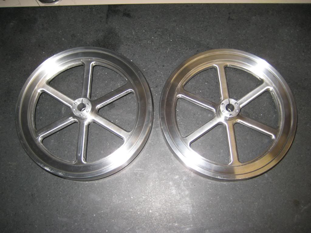
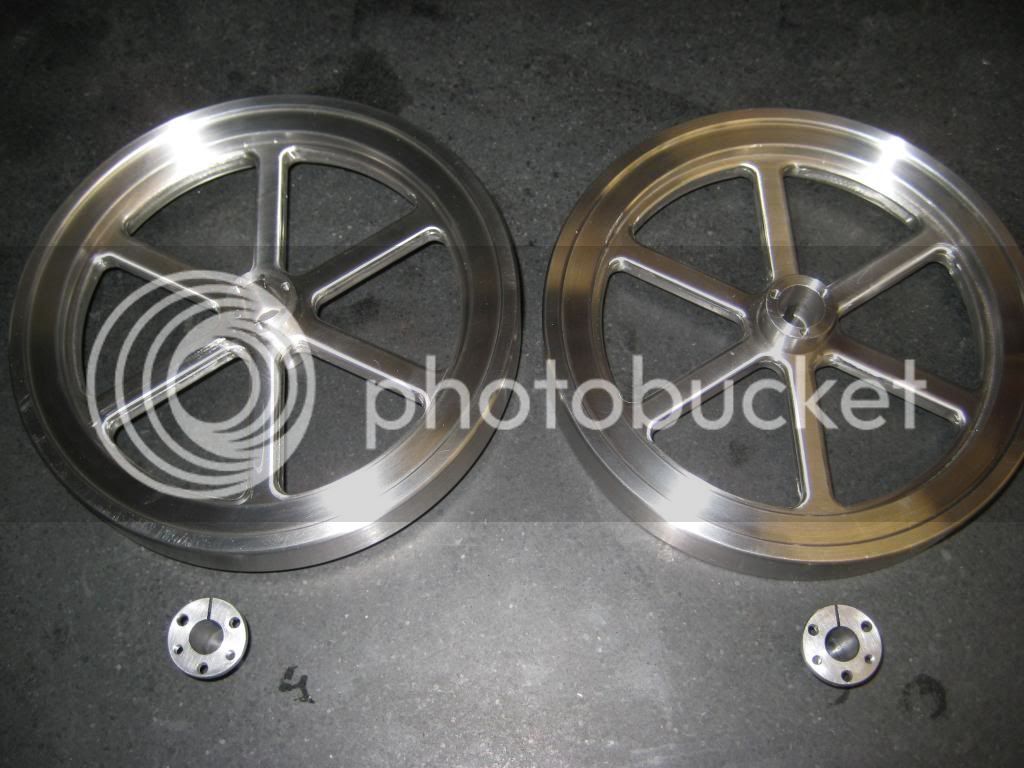
I started the build with the two flywheels and their split collets. Rather than use cast iron for the flywheels, I used 303 stainless and moved the balance feature inboard the appropriate amount to correct for the added density of the 303.

Here are pics of the finished flywheels and split collets:
IMG_1602_zpsfddea6a2.jpg

IMG_1603_zps9ed9af7c.jpg


The Machining Process:
IMG_1581_zps8221f7a7.jpg

IMG_1595_zps93e8f7b8.jpg

IMG_1596_zps20d3d10d.jpg

IMG_1597_zpsd3fee705.jpg

IMG_1598_zps3fb0c9d4.jpg


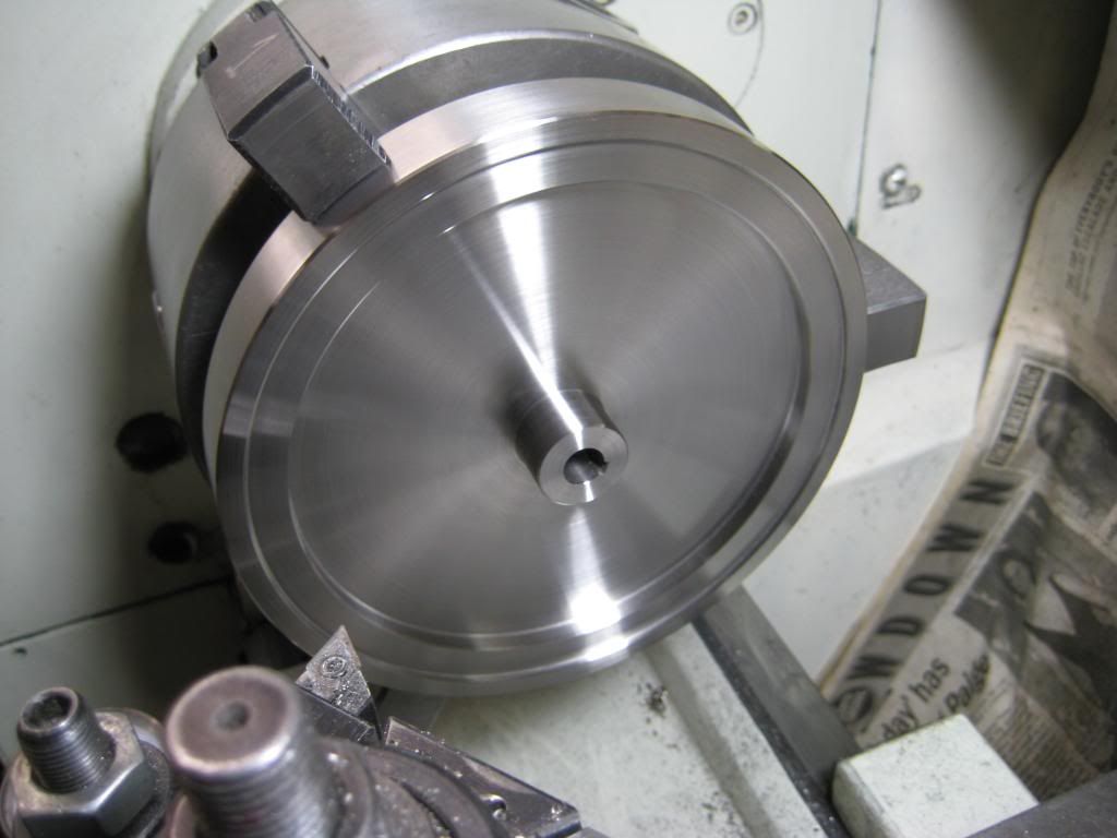
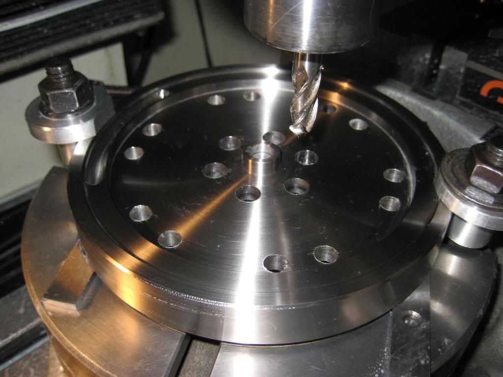
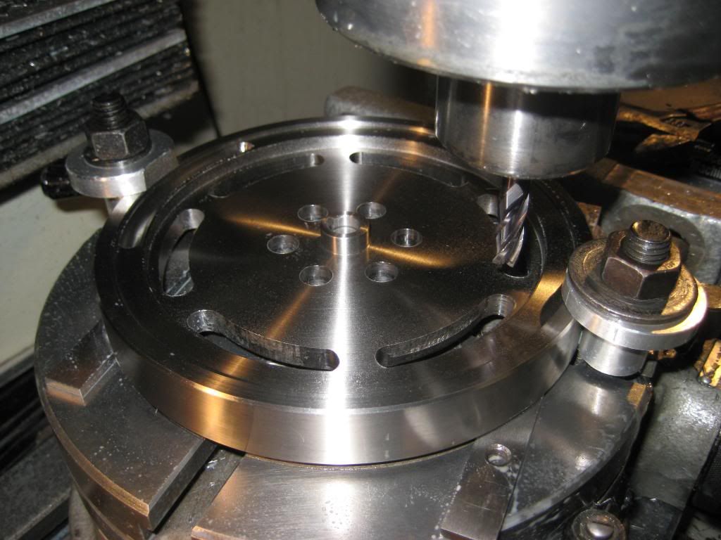
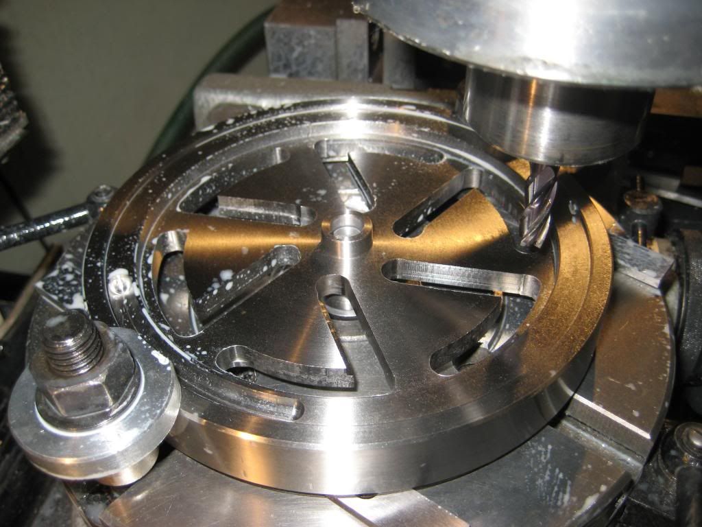
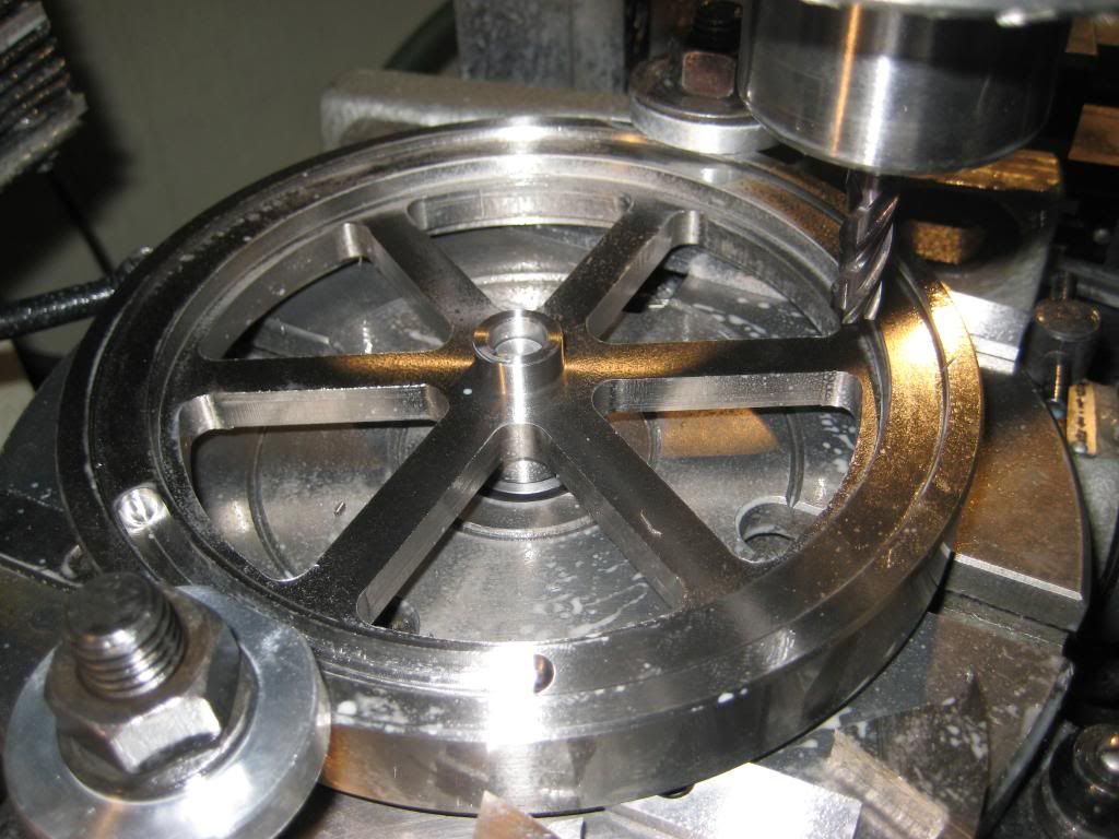
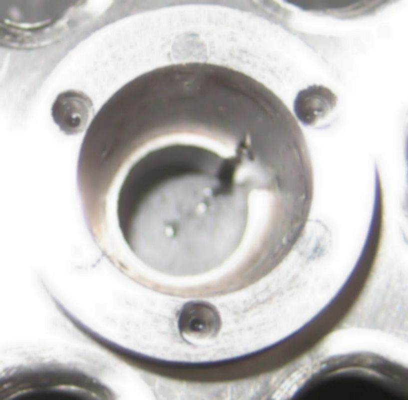
I figured I goof beyond recovery machining the spokes, but that didn't happen. I did however drill the three hub screw holes on the wrong bolt circle by 30 thousandsths. Here's the fixed goof... I just threaded and Loctited in some SS screws, then machined them back to the existing surface both on the face of the hub and the tapered ID.
IMG_1608_zps8f1466f0.jpg


John
 
Nice job!

I have pulled up a chair and look forward to more great posts on your build.

Thanks for sharing your work,
Dave
 
I'm thinking I want to build one of these as my next engine (and my first IC). Looks good so far. Subscribed.
 
Hi John,
Great flywheels. The taper hubs with keyway will securely hold flywheel to crankshaft.
Worked on 48"-----60" flywheels and taperhubs on Ingersoll-Rand Heavy Duty Reciprocating Air Compressors 30-------500 hp.
The taper hubs must be uniformly tightened to prevent distortion.I guess you have provided for removal with built-in jack screws.
 
Nice flywheel John. What's the diameter of the flywheels?

Vince
 
Quick question, did you hand-file the edges of the spokes or did you machine that roundover? They look very nice, but I would think to machine that roundover you'd need a radius bit with a small-diameter equal to the endmill diameter.
 
Quick question, did you hand-file the edges of the spokes or did you machine that roundover? They look very nice, but I would think to machine that roundover you'd need a radius bit with a small-diameter equal to the endmill diameter.

Leatherman,

The roundover was machined with a 1/16 radius round over cutter. As it turns out the round over cutter I chose had close to the right OD for the smaller ID circles on the OD of the spoke cutouts.

For the large radius nearest to the hub, I approached from both edges until I heard the cutter start to "bear." Then, I "blended" it by approaching it dead on, then repeated it offset both to the left and right more or less freehand.

I think my description of the process is as clear as mud, but I'm at a loss for words to describe how I did it.

All: I was hoping to have more parts completed by now, but a cold, followed by pneumonia, followed by another cold, followed by an intestinal virus has knocked me for a loop... I've been under the weather sinice before the holidays and have only had the energy to make the flywheels in the past month....

I did complete a 3D model of the engine in Alibre and plugged it into Keyshot and came up with this:


John

Top Assy.18.jpg
 
Nice model and very nice rendering. Hope you feel better soon.

John
 
Wow nice rendering; I had Keyshot but deleted it as I was short on disc space; now that I have a new PC I should download it again and and give it a try.

Dave
 
Here are the finished flywheels with the drive pulley added:

John

Finished flywheels with pulley.jpg
 
Here is the cylinder head: The valve stems looked all chewed up in the photo, but they were just dirty where they picked up dark oil from the valve guides. All is clean and bright now...

John

cylinder head machining 1.jpg


cylinder head spark plug hole machining.jpg


turning a valve.jpg


Cylinder head parts.jpg


assembled cylinder head 1.jpg


assembled cylinder head 2.jpg
 
Nice looking parts. Be sure to bring them to the NEMES show, everyone likes to see woks in progress, not just finished models. Many of the visitors will have no idea of what the inside parts look like.
 
I'm a bit of a Newbie having completed only one other engine: a PM Research #7 Twin Cylinder Steam Engine from their unmachined casting kit.John

This is an excellent job, Maybe a newbie in engine building but for sure not a newbie in machining which is what it counts.
 
Just found this, very nice indeed.
I bought these plans as well but have not started on them yet.
I will be watching your progress as well.
Gerry
 
Thanks for all the good words so far! Since my last post I've:

1) Made the cylinder liner, piston, wrist pin and wrist pin bushing.
2) Completed the cylinder head. Many springs were wound before I got two I was happy with.
3) Machined the front and rear frame halves.

John

piston and cylinder sleeve.jpg


Cylinder head - assembled.jpg


Frame FnR.jpg


Frame - parts together.jpg


Frame - closeup.jpg
 
Back
Top