Modifing my Bf20 (Following)

Home Model Engine Machinist Forum

Help Support Home Model Engine Machinist Forum:

This site may earn a commission from merchant affiliate links, including eBay, Amazon, and others.

Paolo

Well-Known Member
Joined
Nov 19, 2007
Messages
573
Reaction score
8
Hello All..
Here some pics of my modified Mill....
An old arrangement..I'll show you the actual next days....
DSC02995.jpg

Electronic
DSC03031.jpg

Mechanical
DSC03038.jpg

Testing the arrangement
DSC03036.jpg

more testing...
DSC03037.jpg
 
I'm somewhat concerned as to the way that's wired

[edit]
Sorry after zooming in it's not as it first seemed :)
 
Hey Paolo,

Is that the spindle drive?.

Dave
 
Yes Dave this is!!!!
Monday I'll receive the new bearings...so I'll be able to start to modify the Mill...and restrat to work on the left side wells. Today I conducted the last trial for the electrical connection with box and others stuffs...!
Best regards...
 
Looking forward to your progress Paolo!
:)
Dave
 
More progress
The main spindle done I did a little blackening and I posed a little reflective strep for the spindle sensor!!!
DSC03120.jpg

The main component done
DSC03113.jpg

All cable and controll panel ready to install
DSC03116.jpg

The old light....12Volts
DSC03117.jpg

The new one..5V Led Cree
DSC03119.jpg

Tomorrow I'll try to install all together...
 
More progress today...!!! ;D
The Head
DSC03124.jpg

Column
DSC03122.jpg

Motor
DSC03123.jpg

Main Panel&servoamplifier ready...
DSC03121.jpg

Control Panel and panel light
DSC03125.jpg

ALL together...
DSC03129.jpg

...and finally.....IT RUNS

Some things need to be done ..belt protection and some more....!!!!!! BUT IT RUNS :big:
 
Looks to be some excellent, well-engineered work! Nicely done!
 
Nice work. Im not very CNC literate, but I wanted to ask about the motor mechanics of positioning the head along the z-axis. Does the motor turn the the main vertical threaded lead screw directly via gear reduction? Or is it somehow connected to the shaft mechanism of the crank wheel (the one for manually raising/lowering the head). Maybe that's different than my mill, Ive seen some that are a worm gear & some that are kind of a rack & pinion idea, but Im trying to visualize how they might be connected.

Reason I ask is the topic of gas struts to offset the weight of the mill head was raised in another post here
http://www.homemodelenginemachinist.com/index.php?topic=17844.0

I posted a link on a manual machine installation here
http://homepage3.nifty.com/amigos/60_Gas Spring/GasSpring-e.htm

Will you be using anything like this, or can the motor provide the torque on its own as-is?

How much do you think the assembled head will weigh?


2012-03-10_104032.jpg
 
Hi Swede...
Thanks a lot for your appreciation...
Dear petertha
Yes the step motor turn the main vertical threaded lead ball screw via timing belt reduction and I maintained the shaft mechanism of the crank wheel for manually raising/lowering the head when used manually...The motor is capable to move up and down without problem the head now more than in the past because I reduce weight discarding the electrical box and gears and hold brush motor...so the gas struts is not needed. In effect I didn't have a precise weight of head..I'll test next time I have to remove...Nice idea!! I can estimate about 15 kg more or less..
 
I have the smaller version of yours, the warco WM14 that I would like to change the drive motor as it overheats at full speed using fine cutters, have you got any more information on the main drive system motor you are using and the gear ratio

thanks
Peter
 
Hi Peter
My old motor was 850W..but where power needed..Now I have 1HP Real power...the gear ratio is quite 1:1 and now the spindle runs at 3380 rpm the motor at 3650rpm. I newer reached this velocity!!! I have to do another little improvement like a new motor pulley and I have to modify the rear support for installing the new bigger motor pulley..but not for the moment. I'm building the spindle protection before all. I'll show you as it will be completed. In a few words I compared the old arrangement and I did the new with just a little upgrade just to be conservative...Is a small mill and I have to use it as it is...for my security!!!
 
Great work Paolo! :bow:


....one of these days I'm going to go CNC..... ::)...too many projects!

Dave
 
Thanks Dave....
Yes You have right......too many projects! ::) so We have to accelerate the production infact I'm thinking to modify the lathe also :big:
Best regards
 
are you going to keep your keyboard as it is shown in the first pic?

my keyboard was in the same (ish) place, until a bit of swarf got between the arrow keys that i did know about. so when i moved my table over to the left you can imagine my surprise when the table didn't stop when i let go of the button :eek:
 
Hello blighty...
As i said this was an experimental arrangement...now I have a flexible keyboard and I'm going to place it under the monitor...I'll show as soon as possible the new arrangement...!
Best regards
 
Hi I am hoping to do this conversion but I am having difficulty working out how to get the drive to the pulley from the gear below I can see that it must be via the piece I have arrowed but how does this part connect to the gear below or have you internally splined this part marked with an arrow

thanks

Peter
 
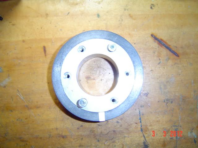
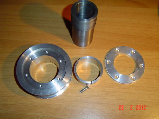
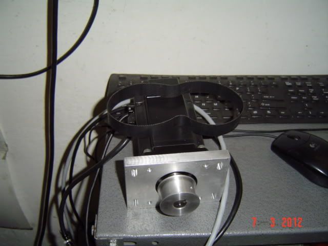
I too am very interested in how you got the upper toothed belt drive pulley attached through the large spindle bearing and onto the lower gear shaft in your setup.

Any chance of going through it a little deeper rather than what you have already shown, just to make it a lot easier to understand, maybe a sketch if you haven't got pics.


Thanks


John
 
Dear friends.....
OK the spindle pulley is attached as shown in the attached drawing ...more clear now? :big: The belt is not a timing belt...and I realized just one prolong inside the shaft fixed by Loctite shown in the picture "main component done". I'm trying to post another schetch showing the original main components!
best regards....

View attachment BeltDriveServo.pdf
 
Following an article about the right light for the mill that was what I have done today using the CNC...I bought the led chain from China..for few dollars. The power supply is 9Volts...!


DSC03227.jpg

DSC03228.jpg

DSC03230.jpg


DSC03225.JPG
 
Last edited:

Latest posts

Back
Top