OilWater Pump for IC Engine

Home Model Engine Machinist Forum

Help Support Home Model Engine Machinist Forum:

This site may earn a commission from merchant affiliate links, including eBay, Amazon, and others.

t_ottoboni

Well-Known Member
Joined
Aug 9, 2009
Messages
68
Reaction score
9
Hi guys!

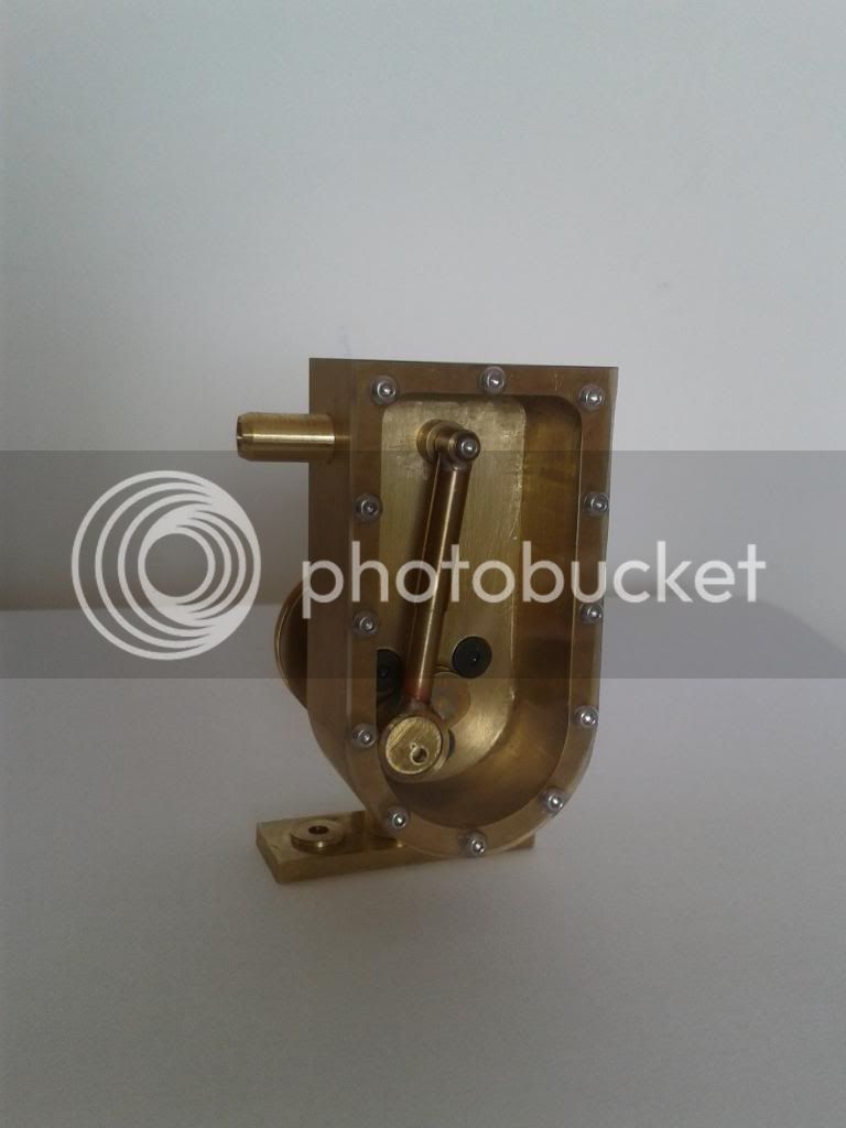
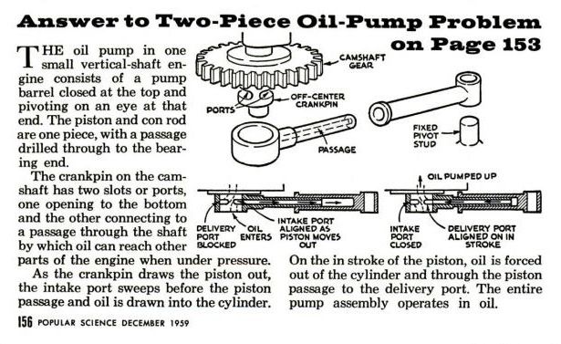
A few months ago I saw this oil pump in Popular Science Magazine and since then I wanted to build one. Instead of an oil pump, I´ll use it as a water pump for a (yet to be built) single cylinder IC engine.

OilPump_zpsd4349db8.jpg


I know it´s a silly project, but for a begginer like me this is a real challenge! =)

I have made the drawings in solidworks (2010), and after I finish this build and if the pump works well, I will share the final version of the drawings.

Montagem2C_zpsc6fc8ed9.jpg

Montagem2C2_zps1c176faf.jpg

Montagem2C3_zpsd1f65529.jpg


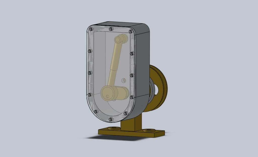
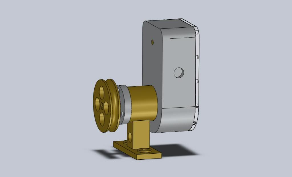
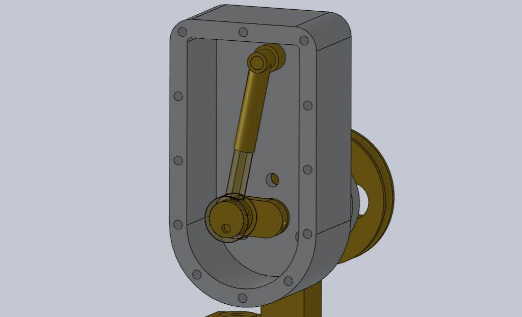
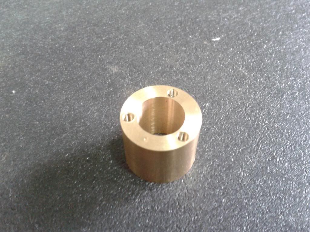
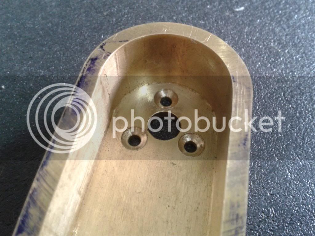
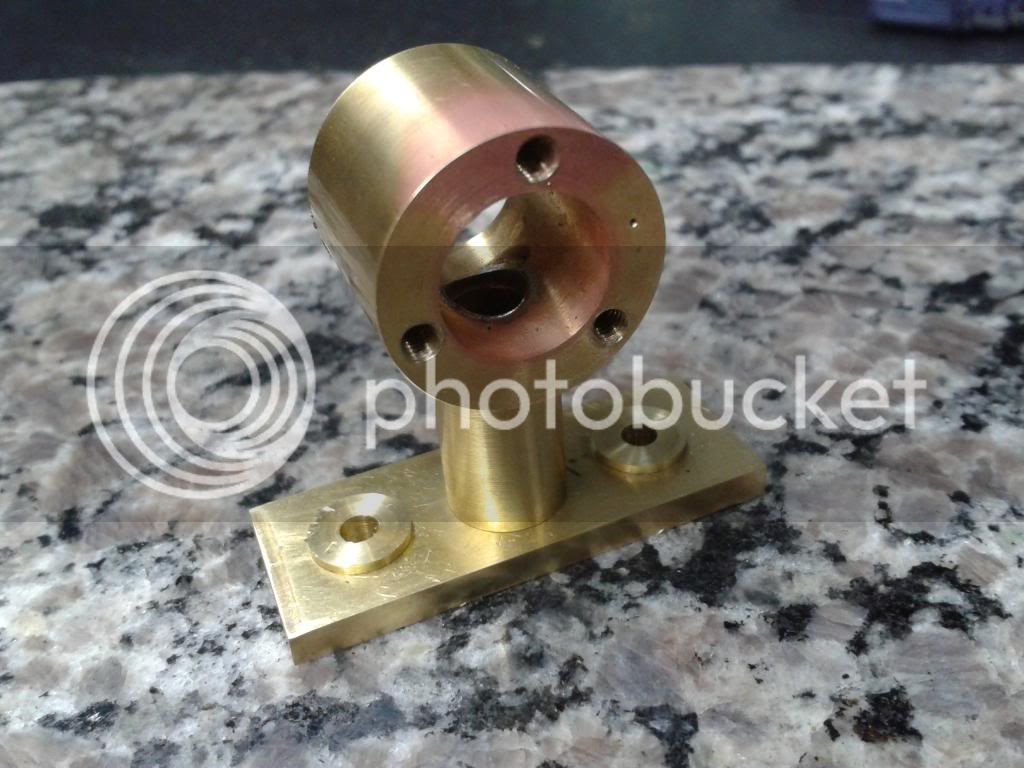
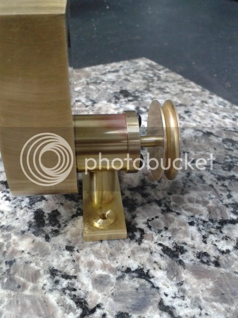
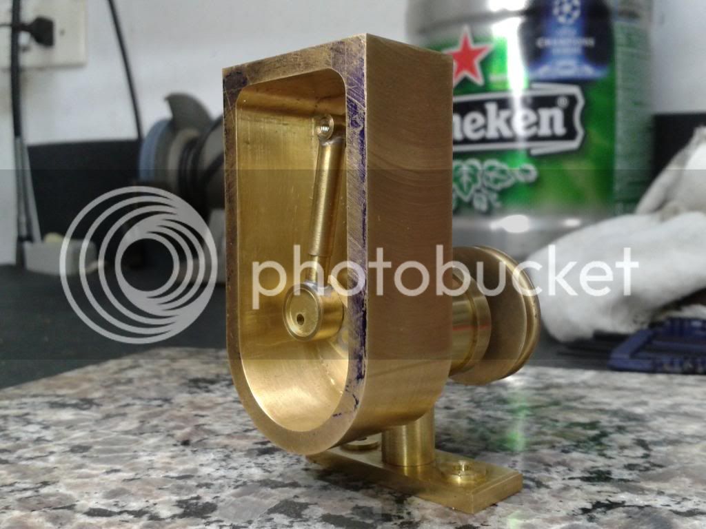
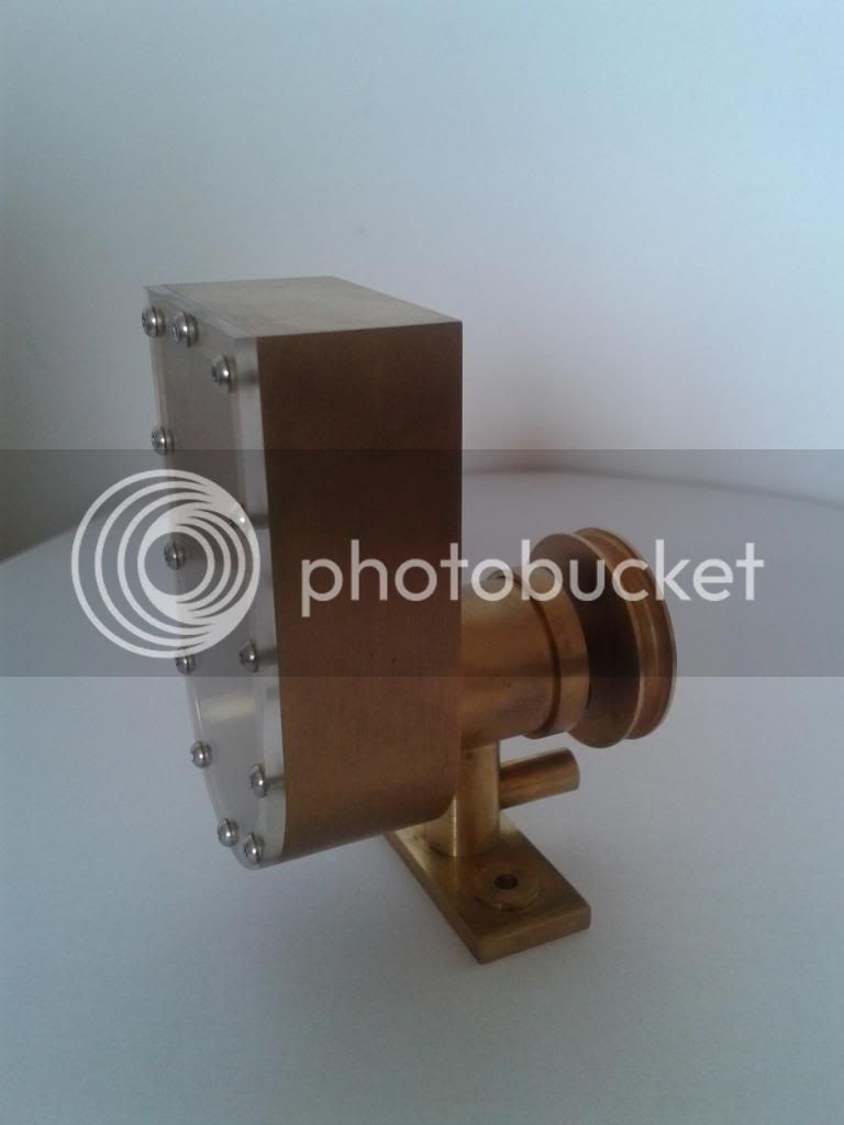
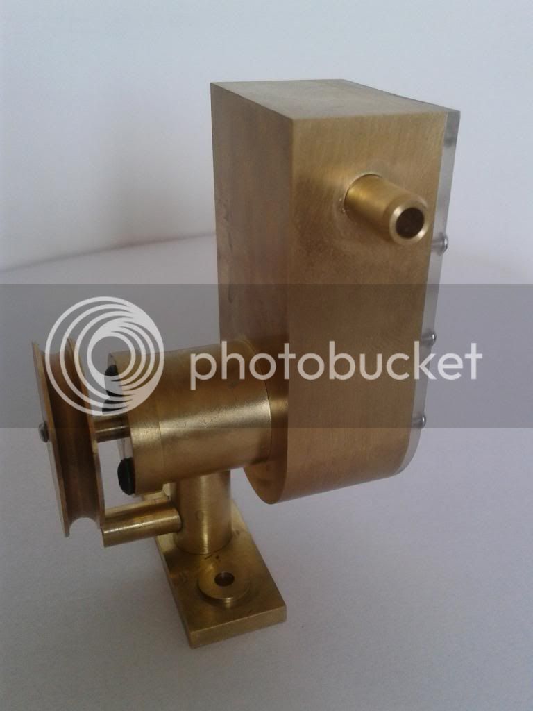
The pump in my drawings have basically two sides: a low pressure side visible through a plexiglass front cover and a high (have no idea how high) pressure side at the "barrel" next to the pulley.

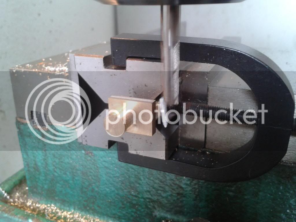
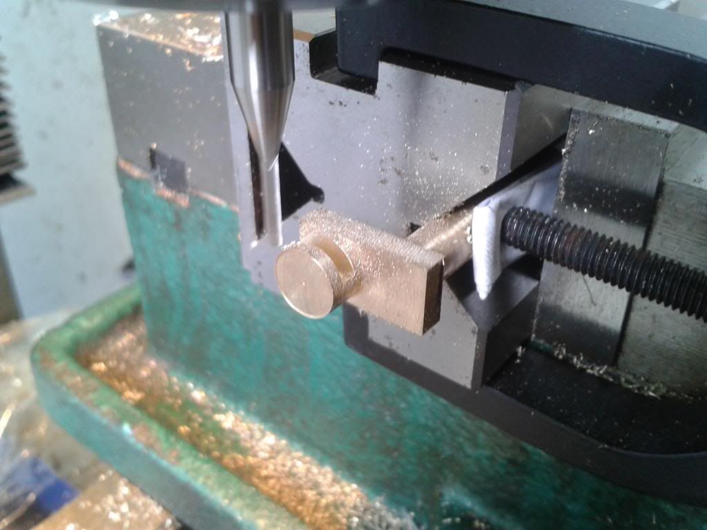
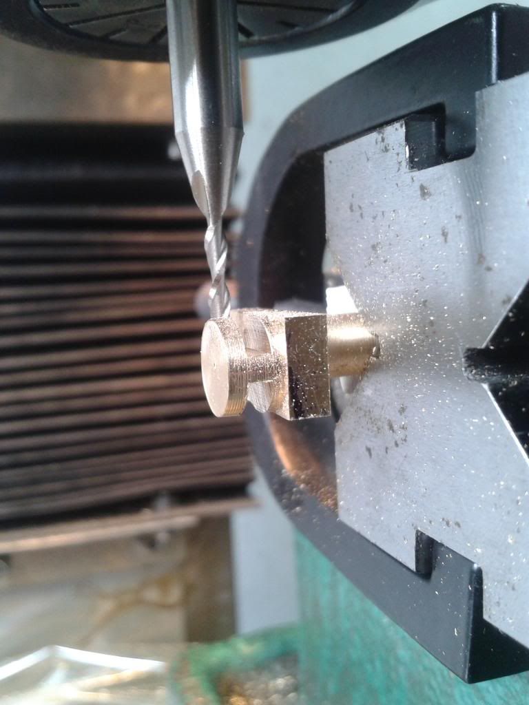
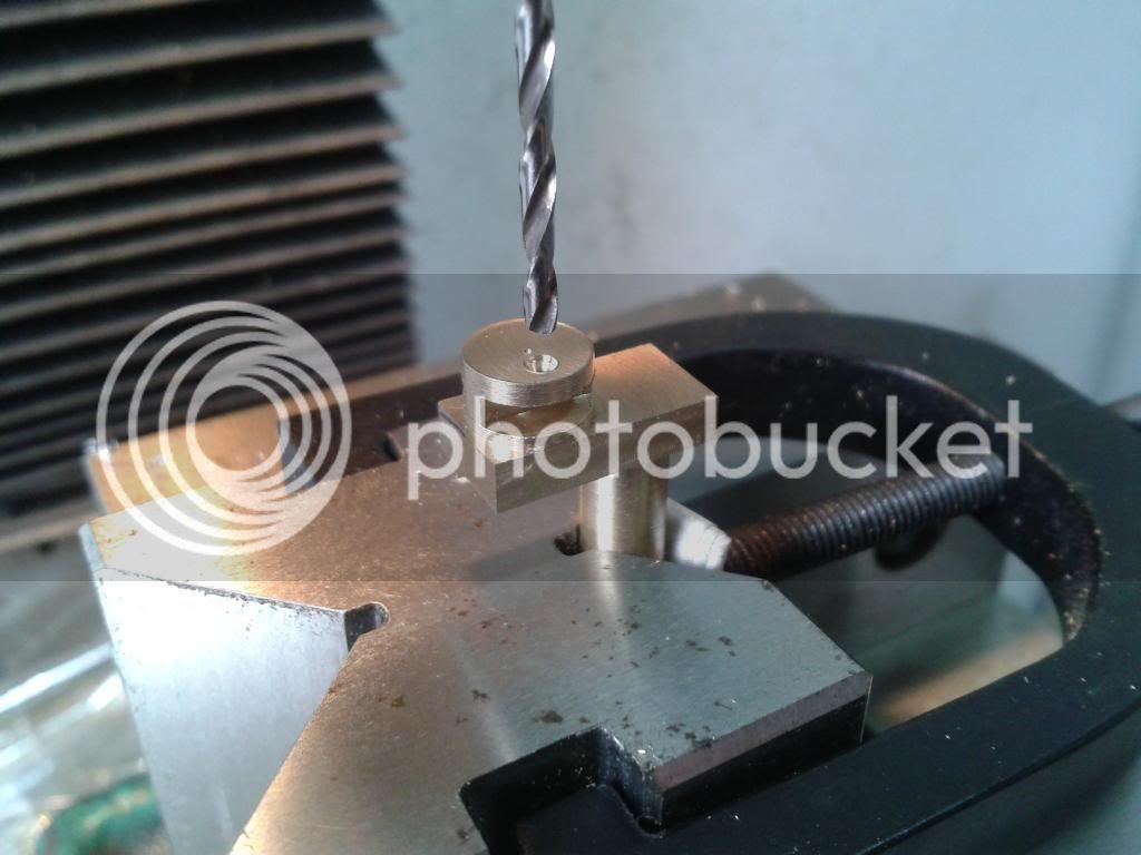
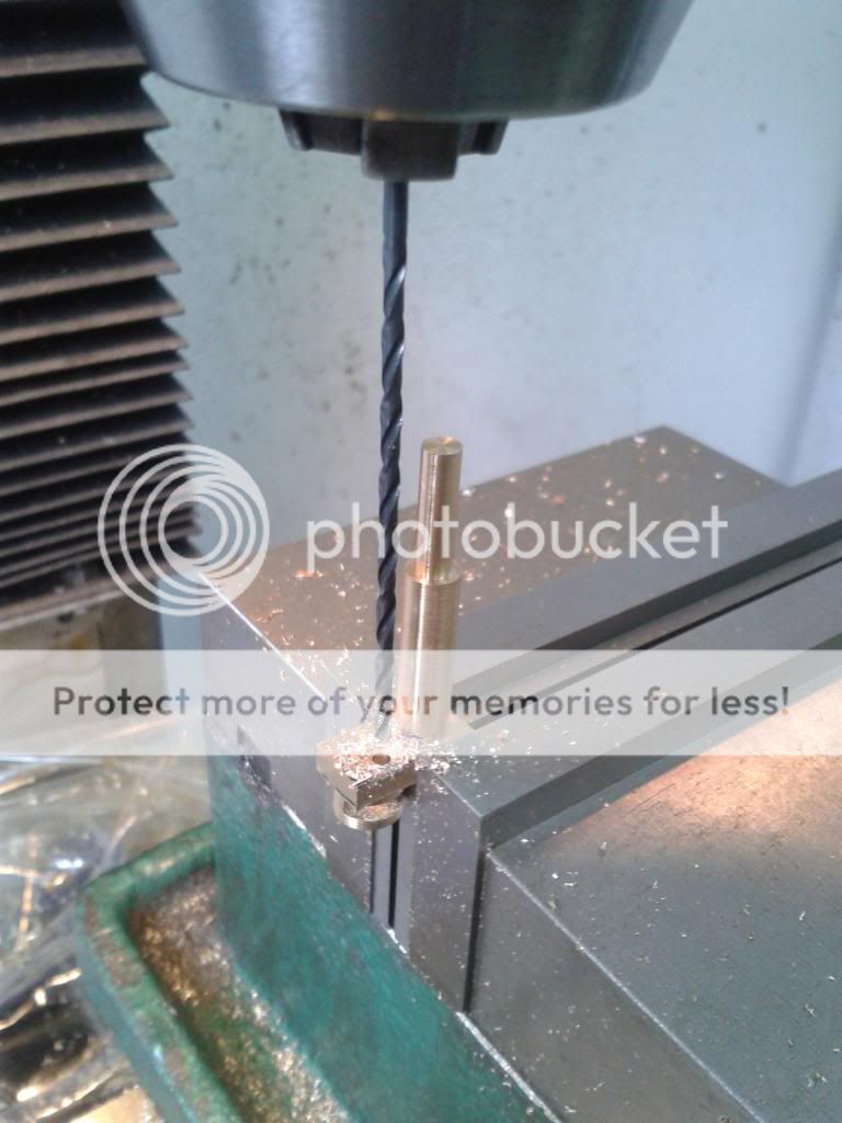
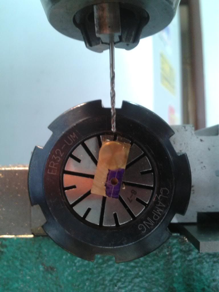
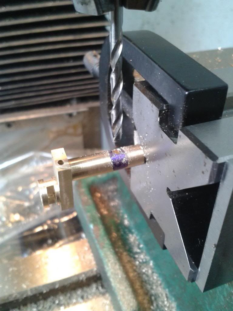
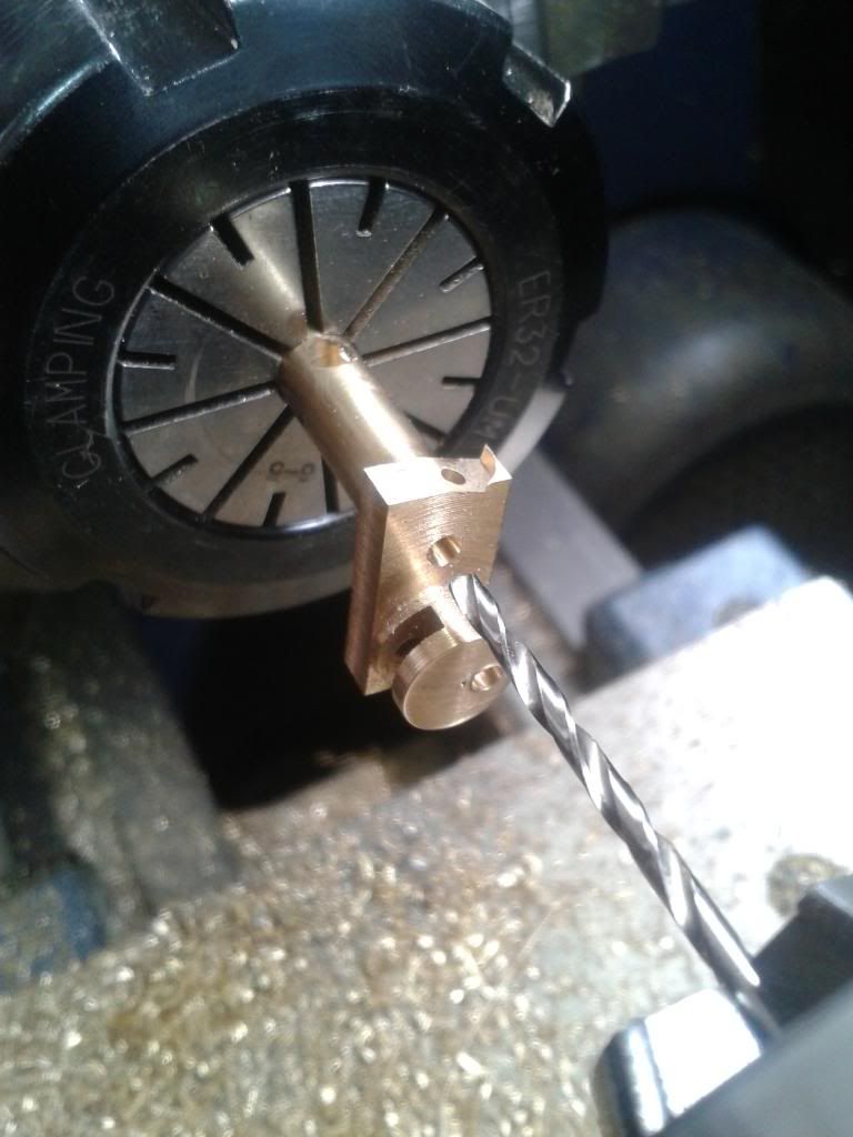
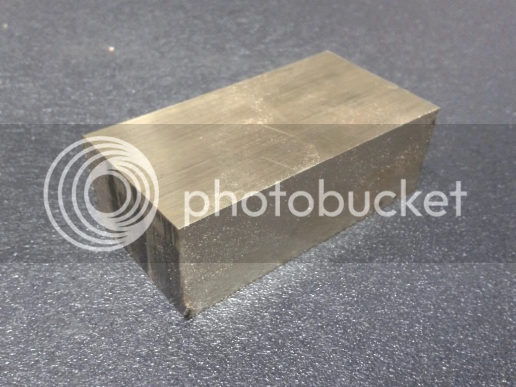
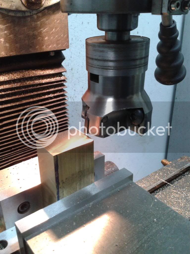
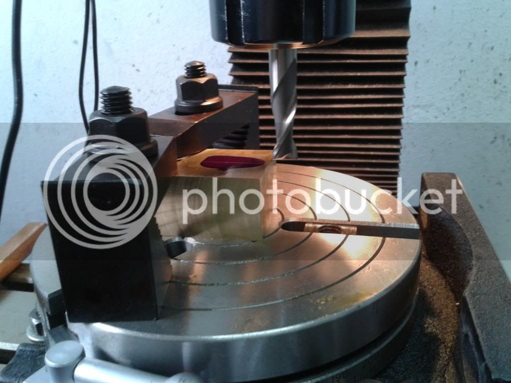
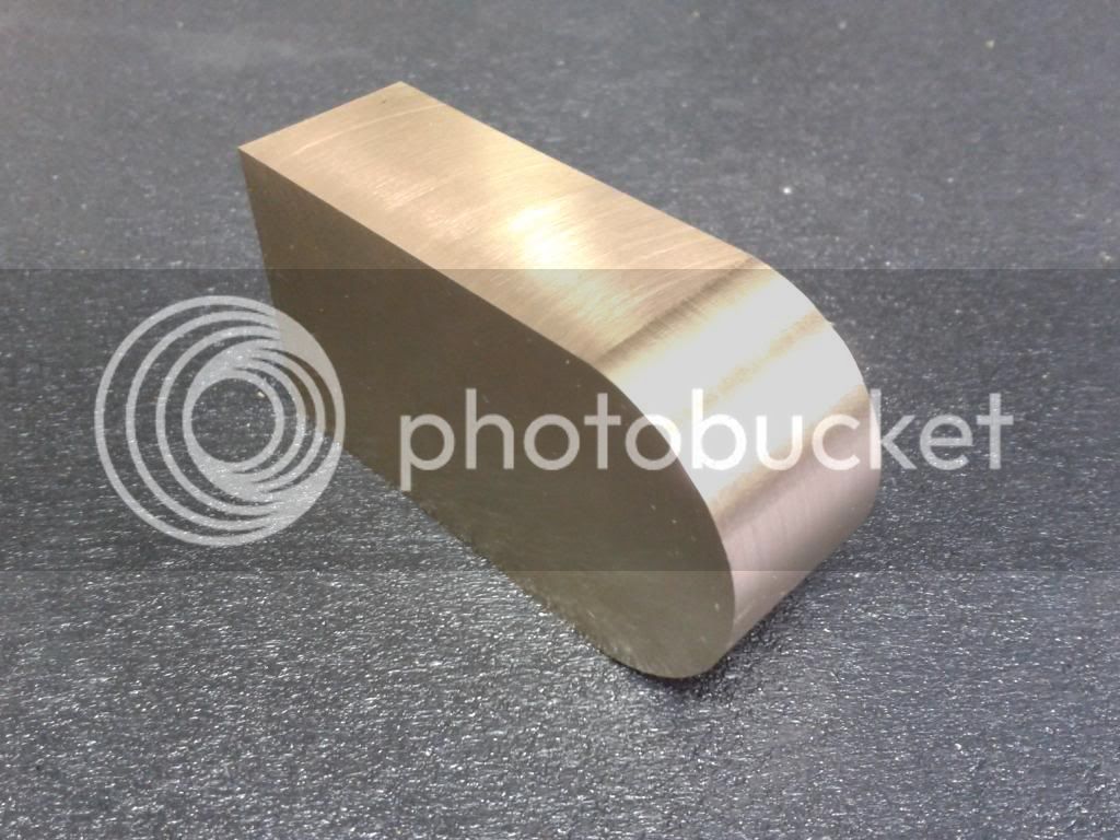
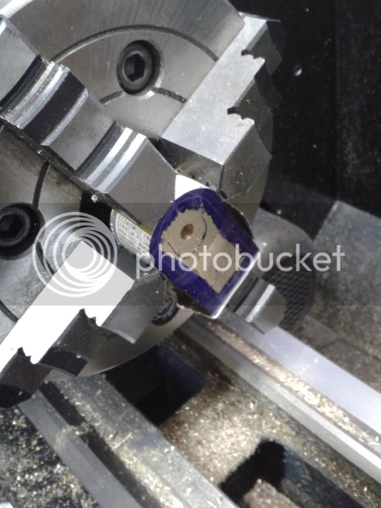
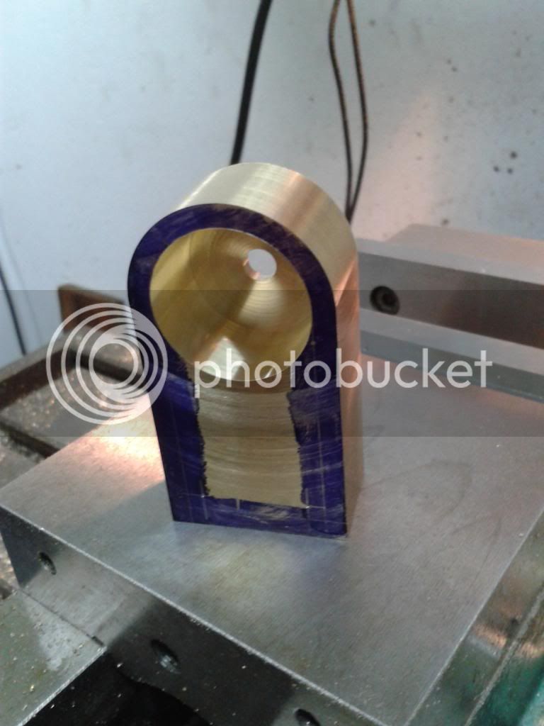
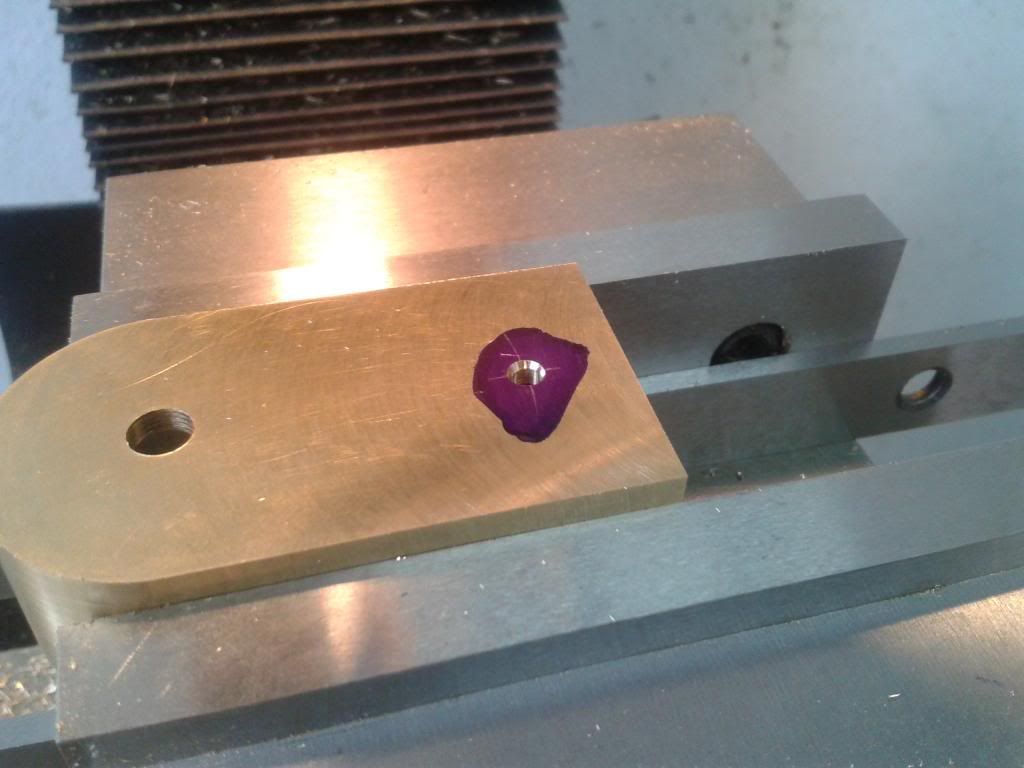
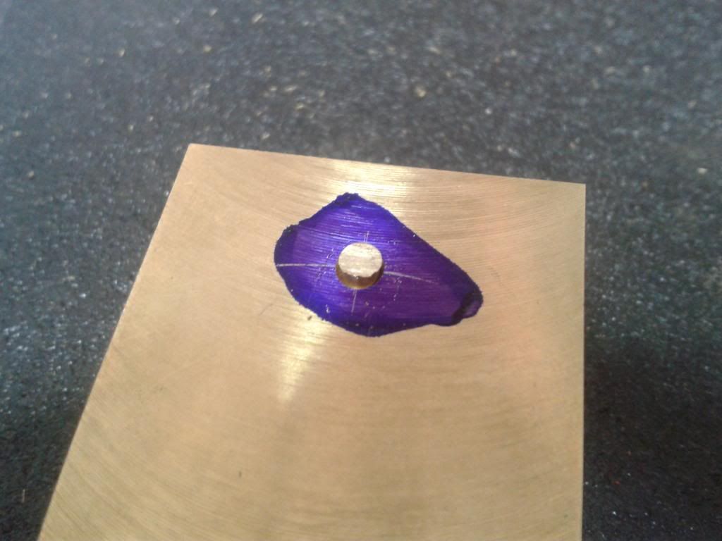
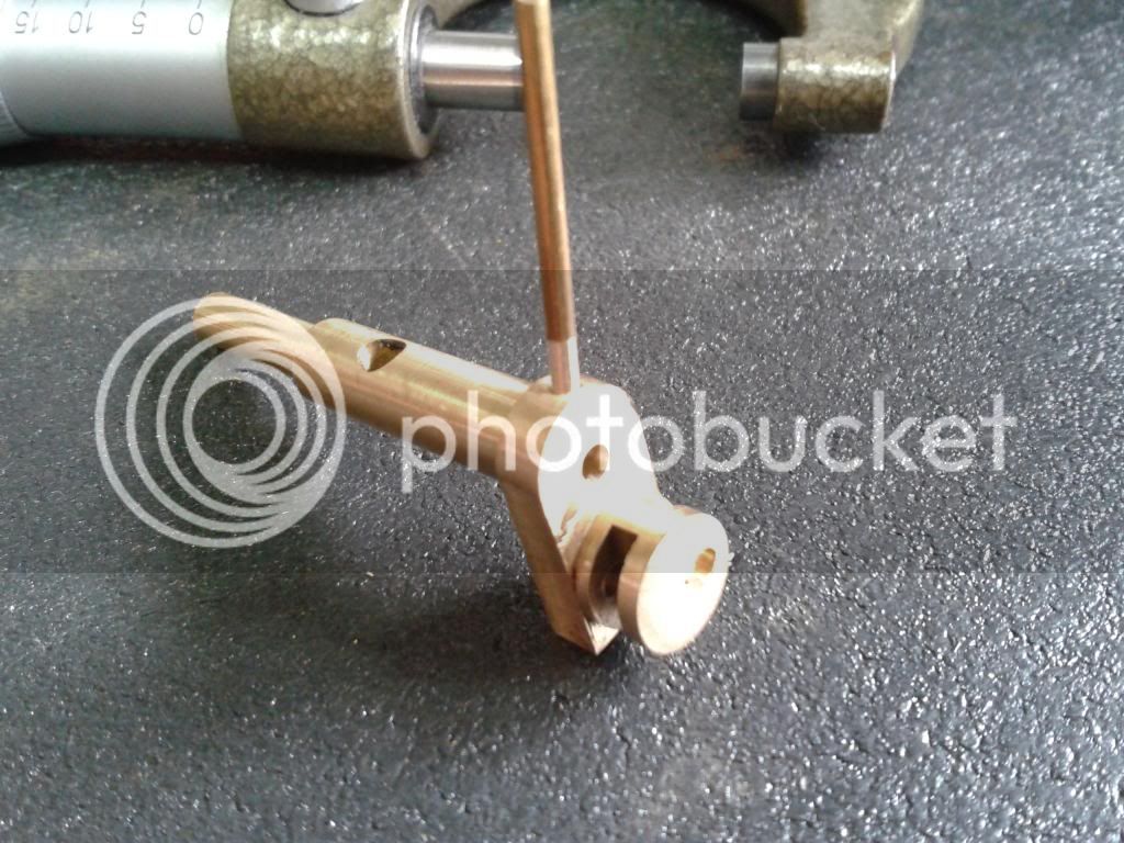
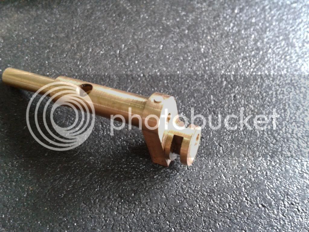
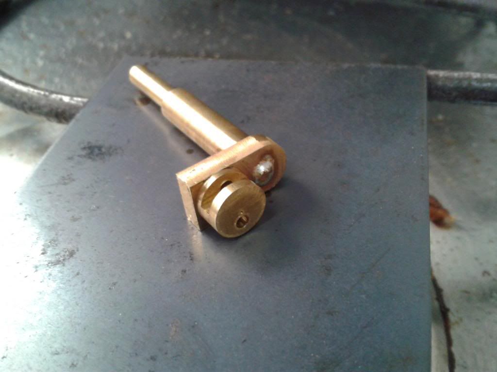
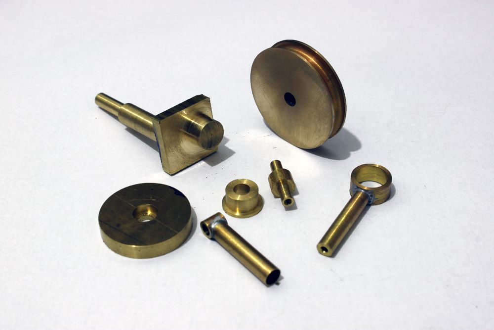
I already started making some parts for this pump and need to buy material for the case and case cover.
The screws that hold the front cover are M2 button socket head and will take a while to arrive here... I bought a lot of 1000 from a chinese supplier and it can take up to 60 days to get in here so this can be a long build (specially if too much leaks begins to appear!)

IMG_4561B_zps60cea312.jpg


I know a gear pump would be much better (and smaller) for an IC engine, but I thing it will be fun to watch this one working through the front cover.. :hDe:
 
Interesting project,

I have seen two examples of this style of oil pump on engines. the first on a Tecumseh lawn mower engine and the second on my 1933 Deutz MAH stationary Diesel engine.
The Deutz has a check ball built in to the eccentric plunger part.

Keep us posted; it will be fun to see it work.

Dave
 
Last edited:
Few updates in the crank:

The crank sides were milled to dimmensions
2013-01-16112031_zpseea42921.jpg


This milling used a 2mm endmill. 4000 rpm and 0,1mm (0,004 in) DOC per pass
2013-01-16114053_zps77da4d97.jpg

2013-01-16114702_zps25fc43ba.jpg


Drilling the ports: The intake port is fairly easy to drill, just a 2mm drill straight port. The "pressurized" port ir a bit more complicated because it envolves 3 holes that intersect each other with a 1,5mm drill. Most of this holes will be plugged to form the port.

Intake port:
2013-01-16120336_zpsf838f64b.jpg


"Pressurized" port:
2013-01-16123803_zps61f3b15e.jpg


2013-01-16124917_zpsc2bc1e86.jpg


Output:
2013-01-16130507_zps22dca42f.jpg


Finishing port drilling: (a little flat was milled for avoiding drill wandering, this corner will be rounded later)
2013-01-16131745_zpsb8180456.jpg


I wish this build was as fast as that of the ohter member here... I still can`t make a part like this one in less than 2 or 3 hours. :wall:
 
These are the oil pumps favoured by Kirby Lauson on their lawnmower engines, seemed very dependable.
Though the delivery will be pulsating of course.
Stew.
 
Last edited:
Thanks for the support, guys!

Finding the right size of brass for the case was a bit difficult, so it took a while to continue this water pump.

First step: cutting the lump of brass to size and squaring it with a 2 1/2" face mill. Although the surface looks like scratched, it's very smooth to touch and only requires a few minutes to sand and polish.

2013-01-30204814_zpsbd38ea48.jpg


2013-01-30215409_zpse7770f56.jpg


Next, mount it to the rotary table and mill the round side of the case:

2013-01-31180414_zpsbd1ca9fe.jpg


Rounding done. A little touch-up with a sand paper before polishing it's all it needs.
2013-01-31191031_zps52009bba.jpg


The case is then mounted in the 4 jaw chuck, center drilled, 6mm hole reamed and the case starts to take shape with the boring bar:

2013-01-31200108_zpsdc5eee1f.jpg


Job done so far:
2013-01-31204258_zpsa8d9567f.jpg


Hope to be able to mill the rest of the pump case this weekend!
very nice project like itThm:Thm:
 
Just made a little more progress in the water pump build:

To place the cylinder pivot, first I countersunk the hole in the outside
2013-02-04141828_zps4aee21e0.jpg


Then the pivot was placed with the pin just about 1,5mm (1/16) protuding from the case
2013-02-04142809_zps8e424d93.jpg


2013-02-04142824_zps60f042f9.jpg


Time to hammer it a little bit
2013-02-04143448_zps6228e024.jpg


I only have to file and sand it smooth now.

I've also made a second crank bushing. A got a piece of teflon, and that will make a much better bushing than the brass.
2013-02-05223845_zpse134eca2.jpg


I also started making the "high" pressure chamber from brass (will be silver soldered to a frame)
Nothing fancy here:
2013-02-05215857_zps9cb485d1.jpg


2013-02-05223740_zpsbcaaaca9.jpg


2013-02-07173114_zps7ef0610e.jpg


The water passage holes in the crank needed to be plugged, So first of all was to make the brass plugs, then solder it with electronics solder and file them smooth. Works like a charm!
2013-02-07145158_zps3ea39e9d.jpg


2013-02-07145550_zps8c88835d.jpg


2013-02-07151235_zps4aab1011.jpg


And finally, the holes inside the pump case were countersunk.

2013-02-07173142_zps36412d10.jpg


Hope to start working on the frame as soon as possible!
 
I'm still following along here; the pump is coming along great!

Dave
 
Awesome job so far Tarik, although I cringed when I saw the amount of brass machined out of the block! Looking forward to seeing the progress on this, very interesting.

cheers, Ian
 
Hi Tarik,
Great job very nice finishing. Very intersting pump project. I will be following this project.
As remenber you are located in Campinas. Is it right? Did you buy the CNC kit for your Milling Machine?
I`m still looking for a supplier for a small CNC lathe (300mm to 400mm distance between centers).

In case you need any help let me know.

Edi
 
Thanks for following this build, guys!

Edi, my machines are all handcranked for now, and will remain this way for a while... :(

Ian, there are golden chips everywhere in the shop! hehe

I've made the "frame" to support the pump case
Inicially, I was going to make the column square shaped, but in a last minute change, I've made it round!
Sorry for finished only pictures, I couldn't find my camera. :wall:

2013-02-10234350_zps5f81afe2.jpg


2013-02-10234000_zpsd3c3dcc6.jpg


2013-02-10234032_zpsd0e75092.jpg


No need to worry about the last photo: The beer keg is a trash can, no drinking while machining (Although the work could go even better :hDe:)

I already found a piece of plexiglass for the case cover, and the M2 screws didn't arrived here yet... As soon as they arrive, I'll touch up everything with a sandpaper and a fine wirebrush for a satin finish.
 
The screws arrived and I managed to finish the parts. I made a quick assembly to check for bindings spots in the shaft. After a couple of minutes for breaking in the pump runs just fine!
I still have to cut some gaskets and polish all the brass to call it finished!

Here are some photos. Sorry for the blurry video, I just can't understand how the cell phone camera decides on where to focus. The video shows the pump at a slow speed at first (almost stalling), and then as fast as my little 12v eletric motor could run.

2013-02-17113558_zpsb1283726.jpg


2013-02-17113508_zps712770e0.jpg


2013-02-17113532_zps1820cd95.jpg


Thanks for following, guys!
 
Back
Top