Yet another Quick Change Tool Post

Home Model Engine Machinist Forum

Help Support Home Model Engine Machinist Forum:

This site may earn a commission from merchant affiliate links, including eBay, Amazon, and others.
Hi Ian

I'm watching this with interest as I'm thinking about making one myself.

I like your "rough machining" setup very high tech. One of the most versatile "machines" there is if you know how to "operate" it. Spindle horsepower is a bit low though and you can't use them for long periods 'cos they overheat.

"Hi Ho, Hi Ho it's off to work we go" might be another suitable musical accompaniment.

Looking forward to further instalments, keep up the good work, (if your arms can take it after all that sawing)

Regards Mark
 
Thank you Mark for your encouragement. Sometimes I think I may have bitten off more than I can chew!

At the conclusion of my last post I said that the next step for building the QCTP's Body would be to machine it's two dovetails. Thinking about it that evening I decided that it would be wiser to first make the matching dovetail of a Reference Tool Holder.
- Having a Reference Tool Holder would help me to ensure that the two dovetails on the Body were identical.
- I could choose the precise dimensions of the Tool Holder dovetail to make them easier to get right with the milling cutters I will be using. This is important because, sooner or later, I will be making at least ten further Tool Holders which must come out quickly(!) all with the same sized dovetail.
- I would get my first experience with machining a dovetail on a Tool Holder rather than on the bigger and more complex Body. Less tears if it should have to redo it!

TOOL HOLDER MATERIAL
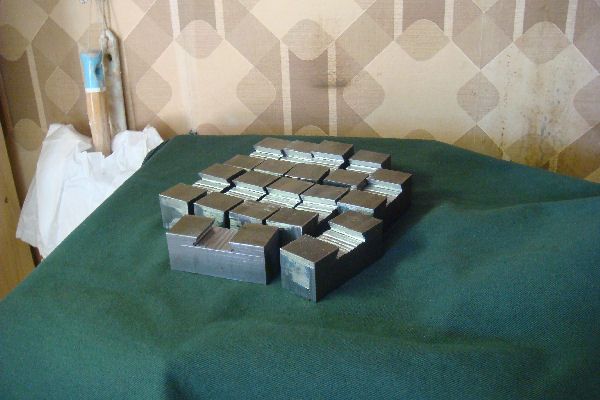
Following the discussions about materials in earlier posts of this thread, I decided that most of the Tool Holders will be made in the steel known in Italy as AVP ie a low carbon mild steel with a dose of lead to facilitate machining. So I sallied forth to buy some square stock of two sizes 30mm X 30mm for full sized Holders and 20mm X 20mm for the mini Holders.

MAKING THE REFERENCE TOOLHOLDER DOVETAIL
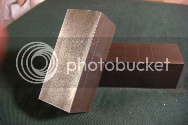
The Reference Toolholder was machined from a 72mm length sawed off this 30X30 AVP stock. The following text refers to dimensions shown on the drawings which are in the Download section of the forum site.

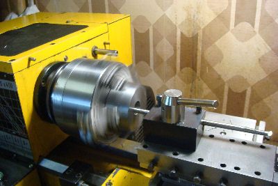
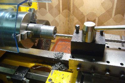
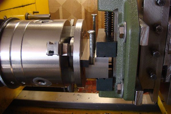
Step 1. Fly cutting the 6 faces
The first step was simply to fly cut all six faces in the following order Bottom, Top, Front, End1, End2 and, for last, the Back face (i.e. the one which would become the dovetail), ending up with a rectangular chunk of size 29 X 29 X 71. The lathe setup and the technique for ensuring that the Ends were square with the Front face were as described in my previous post.
Following this last fly cut of the Back face, the Holder setup was not altered but was left in position in the machine vice ready for machining the dovetail.

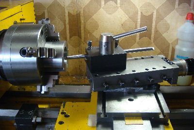
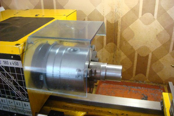
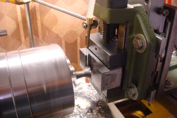
Step 2. Dig the rectangular trough of the dovetail
The trough is 8mm deep (the exact nominal depth of the dovetails) and 25.4mm wide (leaving 0.36mm to be removed from the mouth of the dovetail in the next step).
I used a 19mm diameter end mill with the spindle turning at 400rpm, and made eight vertical cuts (Z axis) of 1mm for each of two horizontal positions: cutter set to offset 3.2mm to the back and 3.2mm to the front. (19 + 3.2 + 3.2 = 25.4).

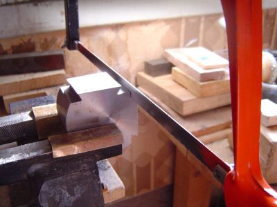
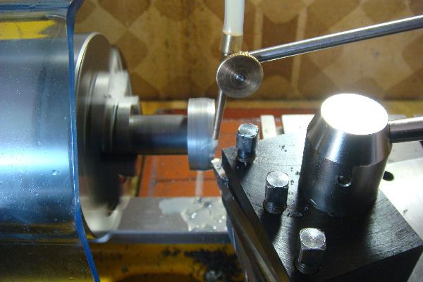
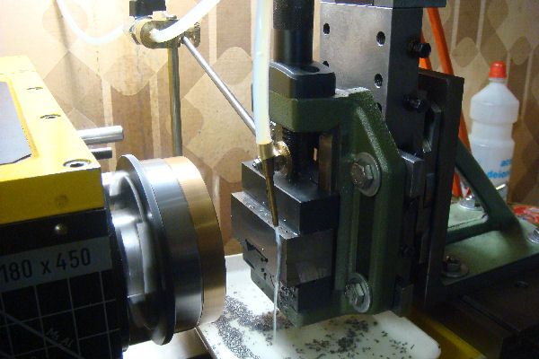
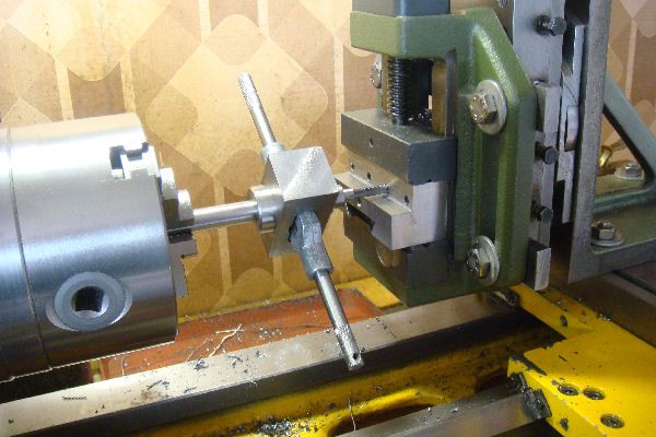
Step 3. Carve the dovetail 60 deg angles
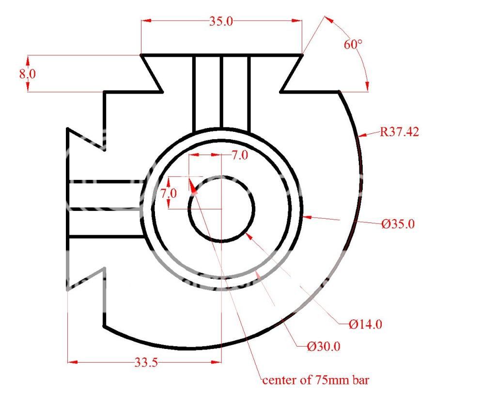
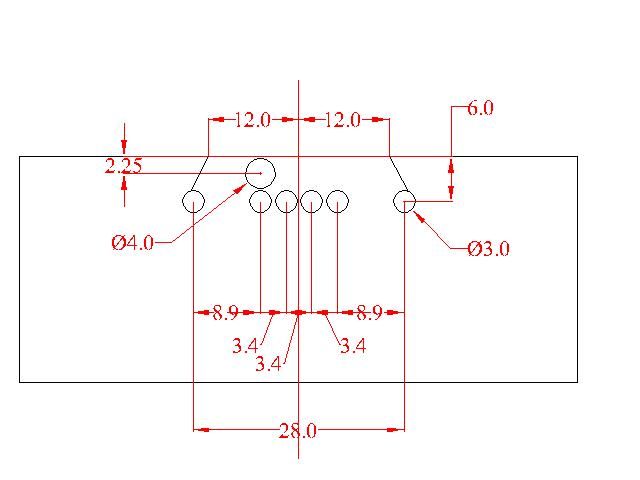
For me this step was where the risk was. It was the first time I made a dovetail and I was a bit nervous about the rigidity of the setup and the resistance of the mill cutter. To remove the metal in reasonably sized cuts I made the plan illustrated diagramatically below.
RefHolder0-DovetailTechnique.jpg

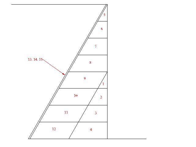
The red numbers indicate the sequence of cuts. Each cut is 1mm deep (X axis) and is therefore wider (Y axis) than the previous cut by cot(60degrees) = 0.57735mm (which is the reciprocal of the square root of 3). The four deepest cuts were tackled in two passes each. Since my 60 degree milling cutter has a diameter of 20mm at the widest, and the width at the bottom of the dovetail must be 35mm, it follows that, at the bottom of the dovetail the Y position of the axis of the cutter must be 7.5mm from the vertical center line of the dovetail. The following table shows the X (carriage) and Y (cross slide) positions of the cutter for the 12 roughing cuts and the three finishing cuts needed for each side of the dovetail. The position X=0 Y=0 means that the center of the widest part of the cutter is aligned with the Front Face of the Holder (X=0) and the horizontal center of the dovetail (Y=0).
Cut Number X(mm) Y(mm)
01 5.00 3.16
02 6.00 3.74
03 7.00 4.31
04 7.95 4.90
05 1.00 3.16
06 2.00 3.74
07 3.00 4.31
08 4.00 4.90
09 5.00 5.47
10 6.00 6.05
11 7.00 6.62
12 7.95 7.20
13 8.00 7.30
14 8.00 7.40
15 8.00 7.50

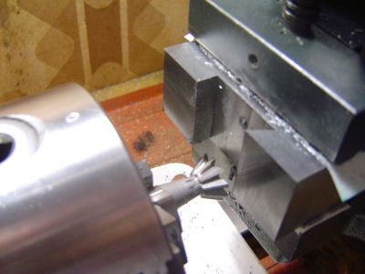
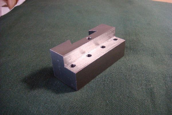
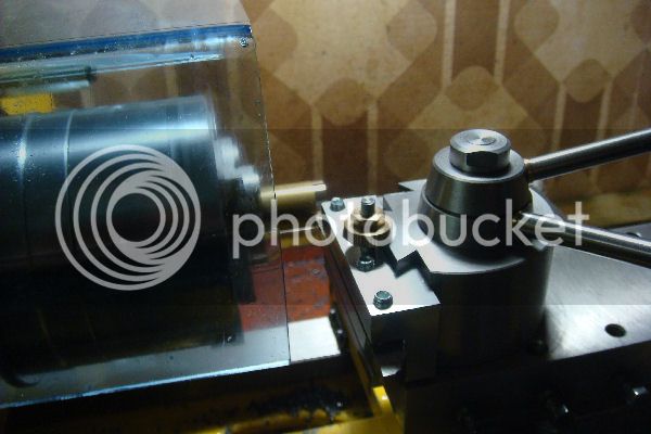
The images below show the progress.

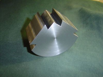
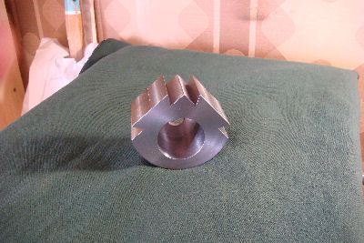
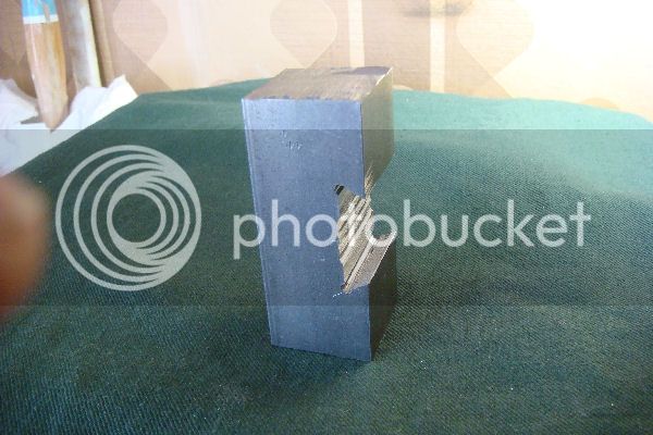
The first edge of the dovetail has been machined.
RefHolder1-FirstTailDone.jpg

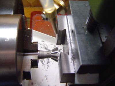
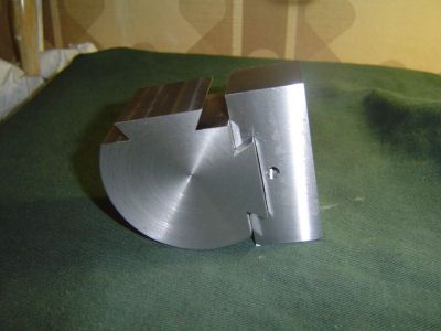
The first 5 cuts of the second edge of the dovetail have been machined.
RefHolder2-5CutsOfSecondTail.jpg


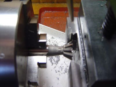
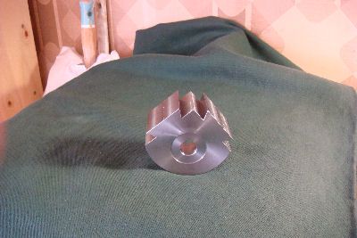
The first 8 cuts of the second edge of the dovetail have been machined.
RefHolder3-8CutsofSecongTail.jpg


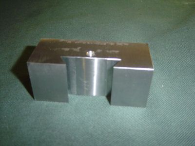
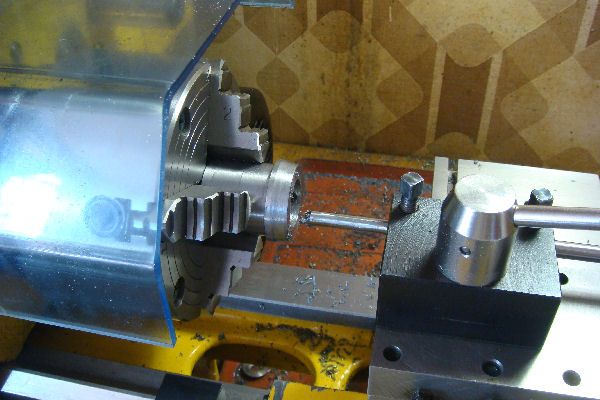
Step 4. Slightly deepen the center part of the dovetail trough. This was done using the 19mm diameter mill cutter, so that only the outer 8mm of the bottom of the dovetail will make contact with the dovetail on the Base. I choose to do this because of a vague fear that tapping the hole for the Height Adjustment Screw would slightly deform the surface, bearing in mind that these surfaces are not subject to stress since the piston pushes the holder away from the Base and so it is the edges of the dovetails which are the real working surfaces.

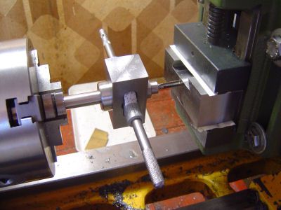
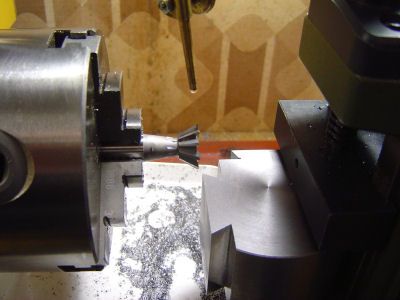
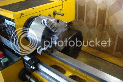
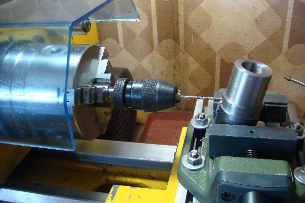
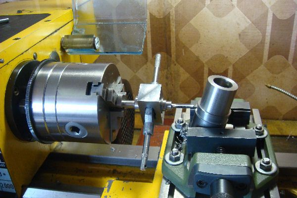
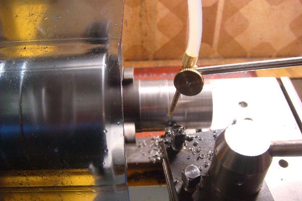
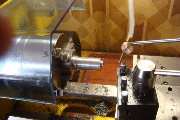
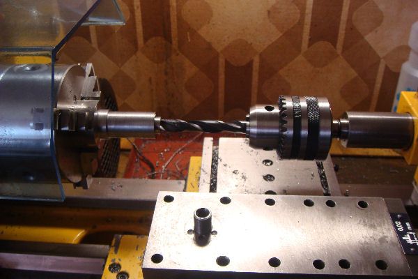
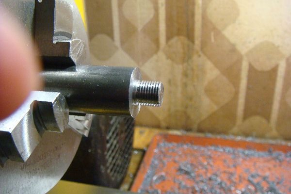
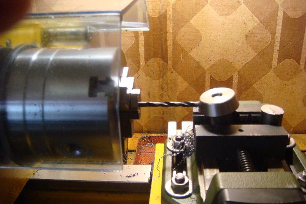
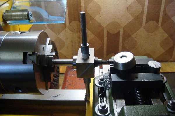
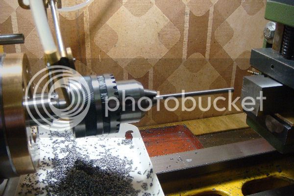
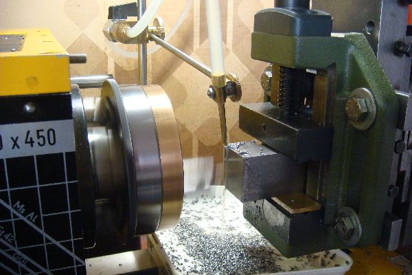
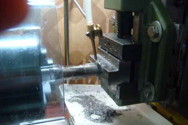
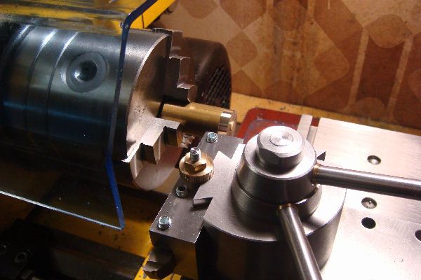
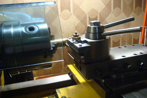
Step 5. Threading the hole for the Height Adjustment Screw.
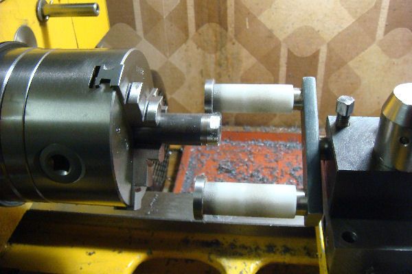
This home made tapping jig keeps the tap axis aligned during the tapping.
RefHolder4-TappingForHeightScrew.jpg


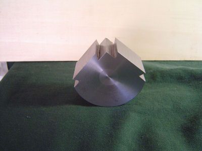
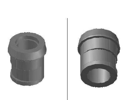
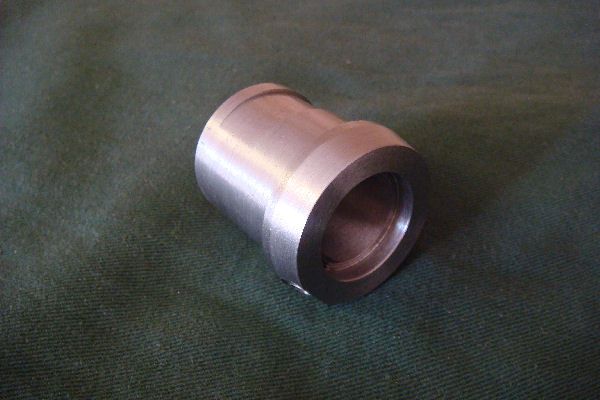
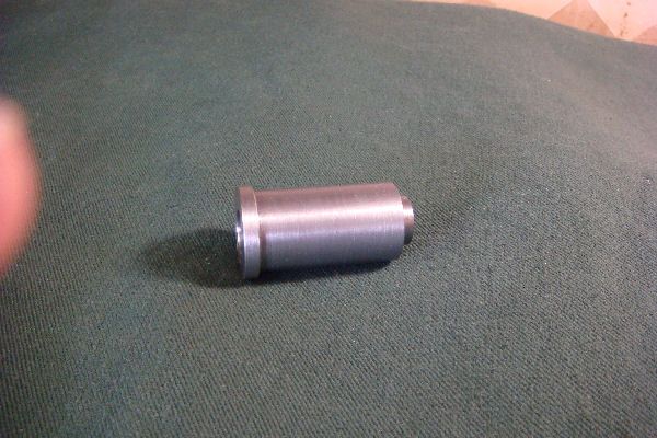
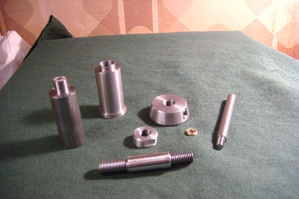
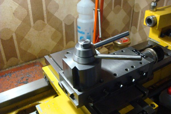
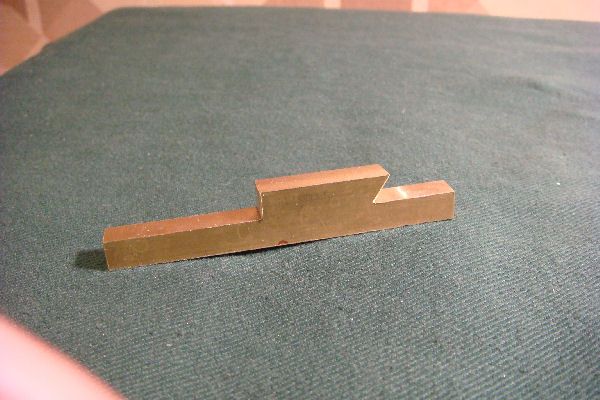
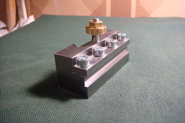
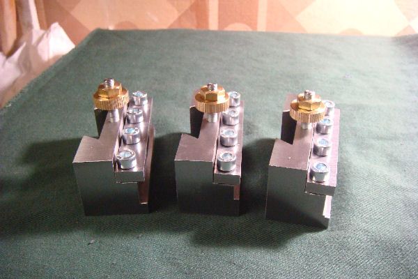
The final image shows the Reference Tool Holder. Now I can proceed to make the dovetails on the Body. Tomorrow is another day...

RefHolder5-Finished.jpg
 
[SIZE=+2]MAKING THE DOVETAILS ON THE BODY[/SIZE]

Armed with my new Reference Tool Holder, I started making the two dovetails on the Body of the
Tool Post.

Rough sawing
As a Home Machinist who is also a Pensioner, I am a firm believer that muscles were invented to
save overworking our machines. An so, as for the two Outer Flats, the work starts by marking out
the dovetails and then removing the bulk of the excess material with a hacksaw.

Body08DovetailsSawing.jpg


I reused I love to go awandering, along the mountain track,.. for rythmic companionship
but noticed that, for some reason, all these tracks seemed to be going steeply uphill.
Nevertheless, at the end of the day I got to 1st base with about 1mm of material left to be
machined off the four surfaces of each of the two dovetails. Here is the pic.

Body09DovetailsSawn.jpg


Final milling

Now I'm ready to do the final milling of the dovetails. I'm a bit nervous because the C40 steel of the Body is quite a bit tougher than the AVP of the Tool Holder. The milling setup of my lathe is exactly the same as was used for the Tool Holder. The dovetails run in the vertical direction
(Z axis) and their position in the horizontal plane is determined by the settings of the carriage (X axis) and the cross slide (Y axis) with respect to the cutter in the chuck. Advancement of the Body against the cutter is done by manually moving the vertical slide, making sure that the direction (up or down) of this advance is opposite to the movement of the rotating blades of the cutter. Thus if for a particualr cutting pass the back of the cutter is doing the work, then the cutter blades are moving upward when actually cutting and so, for this pass, the Tool Holder Body is advanced downwards. This ensures that the cutter cannot pull the metal towards itself faster than I am moving the vertical slide.

I had the cutter rotating at 400rpm and, as for the dovetail edges on the Tool Holder, I took light cuts and removed the material in 8 steps of 1mm while making a compensating 0.58mm adjustment to the Y axis so that the cutter followed the 60deg angle of the dovetail's edge. In this manner I got the dovetail's depth to its final size (8mm) and the dovetail's width down to be only about 0.2 mm too big.

The following picture shows this milling in progress. The nearest edge of the dovetail has been machined in this manner and I'm about to start its other edge.

Body10DovetailsMilling.jpg


The final fitting was done by taking 0.02mm (0.0008 inch) cuts alternately off the entire front and back edges of the dovetail. After each cut I carefully removed any burrs from the borders of
the new cut before trying the fit with the Reference Tool Holder. In the end patience paid off and on the first dovetail I got the nice snug fit I was looking for. Milling the second dovetail went quicker because I felt more confident and because I could leave less material to be removed by the final 0.02mm cuts.

The picture below shows the Body with the finished dovetails.

Body11DovetailsFinished.jpg


This pic shows the Body with the Reference Tool Holder inserted on one of the dovetails.

Body12DovetailsBodyAndToolHolder.jpg


What's next?

The next step for the QCTP Body is to make the bore. I plan to do this using my new 125mm 4 independent jaw chuck. The which however is still without a backplate for mounting it on the spindle of my lathe. So I have to take time out to make a suitable backplate. My Prazimat lathe (made in East Germany) has a spindle interface of the bayonet type according to a now unused DIN standard. I will post a photo of the backplate when I'm done.
 
[SIZE=+2]MAKING THE BORE OF THE BODY[/SIZE]

Having made an adequate backplate for my new 4-jaw chuck, I was in a position to make the bore in the QCTP Body. The main challenge I foresaw was to achieve a sufficiently accurate positioning of the Body in the 4-jaw chuck. Once the Body was accurately positioned in the chuck, I did not expect problems with the actual machining of the Bore.

Mounting the Body in the 4-jaw Chuck

The image below shows the plan view of the QCTP body.

Body13DrawingTopView.jpg


From it one can see that the axis of the bore must be 33.5mm from the outer flats of both dovetails and 30.42mm (37.42 - 7.00) from the orthoganal tangent to each of the curved bulges on the opposite side of these flats. The difference between these two is 3.08mm and I decided to use this fact to position the Body in the chuck.

So, with a 10x10mm tool steel bar with a square end mounted in the toolpost, I turned the chuck until one of the flats was vertical (using a carpenter's square against the top of the cross slide table), wound the cross slide in until the end of the bar was lightly pressed against the flat, and set the index dial to zero. Then I turned the Body 180 degrees (again using the carpenters square against the flat) and wound the cross slide in until the end of the toolbar lightly touched the tangent of the bulge opposite the flat, noting the distance. Then I gently adjusted the positions of the corresponding pair of chuck jaws and repeated the measurment process until the difference between the position of the flat and the position of the opposite bulge tangent was 3.08mm.

Same story for the other flat andit's bulge, and then check again the first one and so on to convergence... During the entire process I had to be careful to ensure that the bottom surface of the Body remained pressed up against the flat face of the chuck.

All this took over an hour. There has to be a better way! Here's a photo of the beast in its cage ready for boring.

Body13In4jawForBoring.jpg


Doing the boring

As I said not much of interest here. The photos show the boring underway and the bevelling of the edges. The latter was done by using the tool for internal metric threads mounted at 1 15degree angle to get an effective bevel angle of 45degrees. Lazy but effective.

Body14BoringUnderWay.jpg


Body15Bevelling.jpg


The result

These two photos show respectively the bore as seen from the top of the Body and the shallow countersink at the bottom of the Body to kelp the QCTP to seat squarely and rigidly on the top of the compound slide.

Body16FinishedBore.jpg


Body17FinishedCountersink.jpg


What's next?

I had in mind to finish the Body by makeing the 12mm holes for the pistons, again holding the Body in the 4-jaw chuck. However I realised that the grip of the jaws on the Body would be too unstable, and so I will have to make these holes by using the milling setup of my lathe. So this will have to wait a bit until I purchase a 12mm end mill. Therefore my new plan is to make the Locking Shaft, i.e. the part which fits into the Body bore and has an eccentric section to press the pistons outward and thereby lock the current Tool Holder.
 
Thank you Paolo! I've nearly finished the Locking Shaft and will shortly post the log.
 
[SIZE=+2]MAKING THE LOCKING SHAFT AND LEVER[/SIZE]

The Locking Shaft is the part which fits into the Bore of the Base and is turned via the Locking Lever at the top so that the eccentric section on the shaft pushes the Pistons outward thereby locking the current Tool Holder in place. Note that I use the term locking to refer to locking the current Tool Holder onto the QCTP and the term fixing to refer to fixing the Tool Post to the top of the compound slide.

The image below from the 3D model shows two views of the Locking Shaft to be built.
LockingShaft01Model3D.jpg


In the meantime I have decided a few design changes.
  • In view of the snug fit of the dovetails on Tool Holder with those on the Body, the eccentricity which moves the pistons is reduced from 2mm to 1mm.
  • To provide better clearance with respect to the mounting rod for the lathe's cooling/lubrification system, the length of the Locking lever is reduced from 80mm to 70mm.
  • The height of the eccentric is reduced from 15mm to 14mm.
  • The threaded hole for Locking Lever is raised 2mm so that the bottom edge of the lever is well above the upper surface of the Base. (This was an error in the original design.)
  • A 2mm spacing washer is introduced on the thread of the Locking Lever to maximize the length of the contact between the threads.
Work Plan


To me the key guiding requirements for planning the work seem to be the following.
  • A snug smooth fit of the outer surface of the Locking Shaft with the bore of the Body.
  • Perfect concentricity of the outer surface and the 22mm bore of the Locking Shaft.

Here is the plan which, perhaps surprisingly, is not as simple as one might expect at first.
  1. Cut a 60mm piece from the bar of 40mm diameter C40 steel stock. This leaves a "Stub" of over 17mm for holding the piece both in chucks and, when the time comes, in the machine vice. (BTW, when the time comes, this Stub may be used to make the hub of the Fixing Lever.)
  2. Face off both ends holding the chunk in the 3-jaw SC chuck. After the second facing operation, the part of the chunk in the jaws of the chuck is what I refer to as "The Stub". Keep the chunk in this position in the 3-jaw chuck for the next 6 steps to ensure concentricity of the outer surface and the bore.
  3. Rough machine the 35mm diameter outer surface of the Shaft for the required length of 32.5mm, leaving about 0.2mm excess on the diameter.
  4. Drill and then rough machine the 22mm bore for a total depth of 44mm (ie 1.5mm more than the overall length of the finished piece, again leaving about 0.2mm excess on the diameter.
  5. Finish machine the 22mm bore.
  6. Finish machine the the 35mm outer surface until the required snug smooth fit into the bore of the Body is achieved.
  7. Bevel the edges of the outer surface, the bore and the shoulder from the outer surface to the 40mm hub.
  8. Set the compound slide to an angle of 10 degrees with resepct to the lathe axis and machine the tapered surface of the Hub. Precision in dimensions and angle is not critical.
  9. Remove the piece from the 3-jaw chuck and drill (5mm) and tap (M6) the hole normal to the tapered surface into which the Locking Lever will be screwed. Hold the piece by the Stub for this drilling and tapping.
  10. Mount the piece by the Stub in the 4-jaw SC chuck, adjusting the chuck jaws so that the axis of the Locking Shaft is 1mm away from the axis of the lathe in the direction opposite to the tapped hole for the Locking Lever. This direction is to ensure that the "open" position of the Locking Lever is on the opposite side of the Tool Post with respect to the Tool Holder to be locked. The Closed or Locked position of the Locking lever will then be almost a right angle to either the right or the left of the Open position.
  11. Machine the eccentric inset into the outer surface to a maximum depth of 1mm.
  12. Remove the piece from the 4-jaw chuck and remount it by the Stub in the 3-jaw SC chuck.
  13. Part off the Locking Shaft to its final overall length of 42.5mm.
  14. Remove the Stub from the chuck and mount the Locking Shaft centered in the 4jaw chuck to make the bore at the top end.
  15. Making light cuts, make this bore to the required 4.5mm depth and diameter of 25.1 mm. Note that neither the bottom nor the sides of this bore make contact with other parts of the QCTP
  16. Bevel the edge of the tapered surface and the inner and outer edges of the new bore.
  17. Make the Locking Lever from a 78mm length cut from 8mm C40 steel bar.
  18. Make the spacing washer from 10mm brass rod stock.
Doing the Job

Here are some pictures of the work in progress.

Rough machining outer surface and bore
LockingShaft02RoughMachining.jpg


The tapered section of the Hub
LockingShaft03FinishedTaper.jpg


Drilling and tapping the hole for the Locking Lever. For drills below 3mm I have to hold a small chuck in the main chuck.
LockingShaft04DrillingLeverHole.jpg


LockingShaft05TappingLeverHole.jpg


The Finished Eccentric. As I have now learnt, the flexibility of the 4-jaw chuck brings with it the challenge of mounting the piece in the right position.
LockingShaft06FinishedEccentric.jpg


Making the bore at the top of the Locking Shaft.
LockingShaft07DoingTopBore.jpg


The Result

Pictures of the Locking Shaft on completion of the above machining, and of the LockingShaft with it's Locking lever inserted in the bor of the Body.
LockingShaft08Finished.jpg


LockingShaft09Mounted.jpg


What's Next?

I plan to finish the Body by making the two 12mm bores for the Pistons, make the Pistons and then, using the Reference Tool Holder, check the functioning of the locking mechanism on both Body dovetails. To start this work I still have to purchase that 12mm end mill...
 
[SIZE=+2]MAKING THE FIXING SHAFT AND ASSEMBLY[/SIZE]

My plan to make the pistons and their bores in the Base floundered because I was unable to find in Rome a suitable 12mm end mill at a reasonable price. So I have ordered one via Internet from CTC tools along with a dial indicator and some HSS stock for grinding up toolbits, hoping not to be disappointed with the quality. One third of the cost is in the insured air postage which, says CTC, may take up to 3 weeks. So in the meantime I have made the remaining parts of the Tool Post, namely the Fixing Shaft and those which make up the Fixing Assembly which fixes the tool post onto the top of the compound slide.

The images below from the 3D model show two views of the Fixing Shaft and a view of the Fixing Assembly; you can see that the latter is composed of five parts.

Fixing01ShaftModel3D.jpg


Fixing02AssyModel3D.jpg


I decided a few changes with respect to the original design.
  • To avoid having to use two different setups to machine what must be concentric surfaces on both the Fixing Shaft and the Fixing Bolt, the bore of the Fixing Shaft now has the same diameter (12mm) over the entire length. In consequence
    • the profile of the Fixing Bolt simplifies to match and
    • the downward pressure on the Fixing Shaft is exerted by the Fixing Hub and not by a central bulge on the Fixing Bolt.
  • To increase the length of active thread holding the Fixing Lever to the Fixing Hub, the diameter of this latter is enlarged from 25mm to 35mm, ensuring however that its lower surface remains clear of the Locking Shaft.
  • The thread at the top of the Fixing Bolt on which the Fixing Hub and the Fixing Lock Nut are screwed, is enlarged from 8M to 10Mx1. (I already have a M10x1 tap set, but I dont have the corresponding die and plan to make the male thread of the bolt on the lathe.)
  • A 2mm spacing washer is introduced on the thread of the Fixing Lever to maximize the length of the contact between the threads.
Work Plan


To me the key guiding requirements for planning the work seem to be:
  • A snug smooth fit of the outer surface of the Fixing Shaft with the bore of the Locking Shaft.
  • Perfect concentricity of the outer surface of the Fixing Shaft and its 12mm bore.
  • A snug smooth fit of the 12mm bore of the Fixing Shaft on the Fixing Stub (a part of the lathe protruding vertically from the upper surface of the lathe's Compound Slide). This Fixing Stub has a vertical bore with an M8 thread which receives the M8 thread of the Fixing Bolt.
  • An appropriate fit of the Fixing Bolt in the bore of the Fixing Shaft. This strange requirement means that the fit of the bolt must not be so tight that the bolt interferes with the horizontal (X,Y) position of the tool post. This position must be determined without interference by the snug smooth fit of the 12mm bore of the Fixing Shaft on the outer surface of this Fixing Stub. The only role of the bolt is to transmit vertical force.
Here is the detailed plan.


Fixing Shaft
  1. Cut a 60mm piece from the bar of C40 steel stock of diameter not less than 25mm. (In fact I used a chunk from a 40mm bar because thats what I've got!) This leaves a "Stub" of over 17mm for holding the piece in the 3-jaw chuck.
  2. Face off both ends holding the chunk in the 3-jaw SC chuck. After the second facing operation, the part of the chunk in the jaws of the chuck is what I refer to as "The Stub". Keep the chunk in this position in the 3-jaw chuck for the next 8 steps to ensure concentricity of the outer surfaces and the bore.
  3. Rough machine the three sections (25mm, 22mm and 14mm) of the outer surface of the Shaft to the required lengths leaving about 0.2mm excess on the diameters.
  4. Drill and then rough machine the 12mm bore for a total depth of 50mm (ie 3mm more than the overall length of the finished piece, again leaving about 0.2mm excess on the diameter.
  5. Finish machine the 12mm bore until the snug smooth fit onto the Fixing Stub on the Compound Slide is achieved.
  6. Finish machine the the 14mm section of outer surface until the snug smooth fit into the bottom bore of the Body is achieved.
  7. Finish machine the the 22mm section of outer surface until the snug smooth fit into the bore of the Locking Shaft is achieved.
  8. Finish machine the the 25mm section of outer surface until a loose fit into the upper bore of the Locking Shaft is achieved.
  9. Bevel all the edges.
  10. Part off the Fixing Shaft to its final overall length of 47mm.
  11. Remove the Stub from the chuck and mount the Locking Shaft centered in the 4jaw chuck to bevel the inner and outer edges of the top.

Fixing Assembly
  1. Fixing Lock Nut Phase 1
    • Cut a 10mm piece from 20mm bar C40 steel stock to make the Fixing Lock Not.
    • Mount the piece in the 3-jaw with about 2mm protruding; face off the end. This face will be the bottom face of the Fixing Lock Not.
    • Use drills to make a central 8.5mm bore right through.
    • Finish bore to a diameter of 9mm and bevel the edge of the bore with a countersink.
    • Tap the bore to make the finished M10 x 1 thread.
    • Remove the partially machined Fixing Lock Nut from the chuck and put it aside.
  2. Fixing Hub Phase 1
    • Cut a 13.5 mm piece from 40mm bar C40 steel stock to make the Fixing Hub.
    • Mount the piece in the 3-jaw with about 2mm protruding; face off the end. This face will be the bottom face of the Fixing Hub.
    • Reduce the outer diameter of the first 0.5mm to 24mm; this "shelf" is to ensure that the downward pressure from the Hub goes only onto the Fixing Shaft and does not interfere with the free rotation of the Locking Shaft.
    • Use drills to make a central 8.5mm bore right through.
    • Finish bore to a diameter of 9mm
    • Enlarge the first 2mm of the bore to a diameter of 10mm (to accept the shoulder of the thread on the Fixing Bolt)
    • Lightly bevel the edge of the bore with a countersink.
    • Tap the bore to make the finished M10 x 1 thread.
    • Remove the partially machined Fixing Hub from the chuck and put it aside.
  3. Make a Temporary Mandrel
    • Cut a 50mm piece from 20mm bar C40 steel stock to make the Temporary Mandrel. This will be used to complete the machining of the Fixing Lock Nut and the the Fixing Hub and also to hold the Fixing Hub in position in the machine vice for drilling and tapping the hole for the Fixing Lever.
    • Mount the piece in the 3-jaw with about 30mm protruding; face off the end.
    • Reduce the diameter to 10mm for a length of 10mm, ensuring a clean and square shoulder.
    • Lathe thread this 10mm with an M10x1 thread using the Locking Nut and the Hub to check the fit.
    • Do not remove the Mandrel from the chuck for the next two steps.
  4. Fixing Lock Nut Phase 2
    • Screw the Fixing Lock Nut onto the Mandrel using a 3mm machined washer to ensure that the mandrel protrudes only 7mm into the bore of the Nut.
    • Face off what will be the top face of the Locking Nut until the overall thickness of the Nut is reduced to 8mm.
    • Bevel the entrance to the threaded bore (using a small boring bar at 45degress if the countersink will not fit).
    • Reduce the outer diameter of the Nut to 19.63mm (the diameter across the corners of a hexagonal section which has 17mm across the flats).
    • Make a 1.5mm bevel at the the outer edge.
    • Use the filing guide to make two opposing flats 6mm wide to receive a 17mm spanner.
    • Remove the finished Fixing Lock Nut from the Mandrel, leaving the Mandrel in the chuck.
  5. Fixing Hub Phase 2
    • Screw the Fixing Hub onto the Mandrel.
    • Face off what will be the top face of the Hub until the overall thickness of the Hub is reduced to 12.5mm.
    • Bevel the entrance to the threaded bore (using a small boring bar at 45degress if the countersink will not fit).
    • Reduce the outer diameter of the Hub to 35mm.
    • Set the compound slide to an angle of 12 deg and machine the conical section of the Hub
    • Make 1mm bevel on both the edges of the conical section at a 45 degree angle.
    • Remove the not yet finished Fixing Hub from the Mandrel and put it aside.
    • Remove the Temporary Mandrel from the 3-jaw and put it aside.
  6. Fixing Bolt
    Make from a 70mm length piece of 12mm c40 steel bar. Enjoyable exercise in threading on the lathe! Note that the bolt must not fit too well in the bore of the Fixing Shaft especially at the bottom end.
  7. Freliminary Assembly

    This step mounts the Tool Post onto the lathe's compound slide for the first time in order to determine the correct angular position on the Fixing Hub for the threaded hole for the Fixing Lever.
    • Screw the Fixing Hub onto the Fixing Bolt and tighten it down onto the shoulder.
    • Screw the Fixing Lock Nut onto the Fixing Bolt and tighten it down against the upper surface of the Fixing Hub.
    • Insert the Locking Shaft into the Base and the Fixing Shaft into the Lock Shaft.
    • Position these carefully onto the Fixing Stub protruding from the compound slide, and position them wit.
    • Insert the Fixing Bolt into the Fixing Shaft and use a spanner on the Lock Nut to fix the Tool Post firmly onto the compoud slide.
    • On the Fixing Hub, mark the angular position required for the Fixing Lever.
    • Remove the Tool Post from the compound slide and dismantle it.
  8. Fixing Hub Phase 3
    Mount the machine vice on the cross slide of the lathe, screw the Fixing Hub onto the Mandrel, and mount them in the machine vice to make the threaded hole for the Fixing lever in the manner alredy desribed for the Locking Lever hole in the Locking Shaft.
  9. Locking Lever
    Make from a 76mm length cut from 8mm C40 steel bar.
  10. Spacing Washer
    Make from 10mm brass rod stock.
Doing the Job

Here are a few pictures of the work in progress.

Rough machining the outer surfaces of the Fixing Shaft.
Fixing03ShaftRoughing.jpg


Rough machining finished for the outer surfaces of the Fixing Shaft.
Fixing04ShaftRoughingDone.jpg


Drilling the bore of the Fixing Shaft
Fixing05ShaftDrillingBore.jpg


Finished Fixing Shaft
Fixing06ShaftFinished.jpg


The Temporary Mandrel in the 3-jaw chuck
Fixing07Mandrel.jpg


Filing the flats on the Fixing Lock Nut
Fixing08NutFilingFlats.jpg


Machining the conical section of the Hub
Fixing09HubCuttingCone.jpg


Drilling and Tapping the hole in the Fixing Hub for the Fixing Lever
Fixing10HubDrillingLeverHole.jpg

Fixing11TappingLeverHole.jpg


The results

The picture below shows the finished parts mentioned in this post, including the Temporary Mandrel.

Fixing12FinishedParts.jpg


The picture below shows all the parts of the QCTP assembled and mounted on the compound slide of the lathe.

Fixing13MountedToolPost.jpg


The attention paid to certain surfaces being concentric and to getting snug smooth fits bewteen certain surfaces seems to have paid off because:
  • the Fixing Assembly turns smoothly while screwing down into the thread of the slide's Fixing Stub and then fixes the Tool Post very firmly on the top of the slide without requiring undue force;
  • With the Tool Post firmly fixed down on the slide, the Locking Shaft turns smoothly in its cage between the bore of the Body and the outer surface of the Fixing Shaft.
What's Next?

To finish the Tool Post I need to make the pistons and the holes for them in the Body and then pay some attention to the finish on the visible surfaces. This will happen when my 12mm end mill arrives from CTC.
In the meantime I shall of course start the rather dauwnting task of making some Tool Holders; a dozen or so would be nice ...
 
[SIZE=+2]TOOL HOLDERS: GETTING STARTED[/SIZE]

Planning the Odyssey

In a post some time ago a dour HMEM member warned that the just reward for the unwary who make themselves a Quick Change Tool Post is to spend the rest of their lives making Tool Holders for the darn thing. Being still young enough (at heart I mean...) to be unwary, I started my QCTP on impulse, and so find myself now in the position of having a Tool Post (well nearly) but nary a single Tool Holder to grace it. Darkly, I glimpse the rest of my life as a daily struggle to finish the next Tool Holder before my supper gets too cold.

Clearly urgent steps are required to scotch this nightmare.

Firstly I made a rapid and irrevocable decision not to throw away my lathe's original single position Slow Change Tool Post and the associated heap of shims. Not only could I even use it when all else failed (who would ever know?), but in times of lesser stress I could open the draw and look at it with fond remembrance and even spend a wink or two.

Secondly I tried to give a dimension to the problem by making a list of the Tools and the appropriate Tool Holders which would constitute a minimum useful set. This list is based on what has been my personal practice and has no pretence to be valid for anyone else. I have always ground my own bits from HSS stock - 10x10mm or 8mm round for big ones, and 6x6mm or 5mm round for small ones, excluding parters. The list came up with over twenty tools requiring fifteen different types of Holder. The attached Excel file contains two worksheets: the first lists the tools, the second lists the types of holder. The relatively high number of types arises partly from supporting two sizes of tool and partly from designing the Holders so that they position the tool not only at the right height but also at the right horizontal angle. In fact the names I have chosen for the holder types show a) the basic shape of the holder (Slot, Shelf, or Hole), b) the dimension of the supported tool section and c) the horizontal angle (degress left or right) of the tool shank with respect to the dovetail on the holder. The design concepts of the three basic shapes where essentially copied from the design published by Nifty which I cited in the first post of this thread.

Thirdly I made detailed CAD design models for the fifteen types of Tool Holder; the derived drawings are shown in the four attached pdf files.

Fourthly, not wanting to embark on making over twenty holders in a single batch, I made a selection of twelve tools for which to build appropriate holders and so embark on making a first batch of 12 holders. One of the twelve partially exists already in the form of the Reference Tool Holder I prepared before machining the dovetails on the Tool Post Body.


Fifthly, I clarified the key criteria and made a rough mental plan for doing the job.
  • I would machine the features common to all the holders before doing the features which depend on the holder type. The common features are the top face, the bottom face. the two end faces, the dovetailed face to fit the tool post, and the height adjustment mechanism and related fixing hole.
  • To reduce the wear on the dovetail end mill I would use manual methods to remove most of the material from the dovetail recesses.
  • Thus, for machining the common features the steps would be:
    1. Make twelve sets of stud, wheel and lock nut for height adjusters.
    2. For all eleven new holders mark up and rough cut the dovetails.
    3. For all eleven new holders fly cut the top and bottom faces for a finished height of 29mm.
    4. For all eleven new holders machine the dovetail face, including the dovetail itself, with the method already used to make the Reference Tool Holder.
    5. For all eleven new holders fly cut the two end faces to have an overall length of 71mm with the dovetail in the center.
Photos showing progress to date.

Here are the twelve sets of pieces for the height adjusters.
Holders01HeightPieces.jpg


These are two of the eleven chunks of AVP (roughly 30 x 30 x 74), showing the markings for the manual removal of material from the dovetails.
Holders02DovesMarkedForSaw.jpg


This drawing shows the positions and sizes of seven holes drilled in each holder to facilitate starting the rough cutting.

Holders07DoveHoles.jpg


Here is the first of the holders after doing the rough cutting with a hacksaw first with a round blade (2mm) and then with a normal flat blade (13mm).
Holders04DoveRoughCut.jpg


These are all eleven holders after this rough removal process.
Holders05AllDovesRoughCut.jpg


This photo shows the setup for flycutting the top and bottom faces.
Holders06FlyCuttingTopFace.jpg


What's Next?

So far I have spent about an hour on each holder to rough cut the dovetails and then flycut the top and bottom faces. The next step is to machine the dovetail faces and its dovetail; rather more challenging than the previous steps!

View attachment Tool Holders.xlsx

View attachment Tool Holders Slot6.pdf

View attachment Tool Holders Slot10.pdf

View attachment Tool Holders Shelf.pdf

View attachment Tool Holders Hole.pdf
 
Last edited:
[SIZE=+2]TOOL HOLDERS: MACHINING THE DOVETAILED FACE AND THE END FACES[/SIZE]

Approach


This step has two sub-steps; each performed on all eleven new holders.
  • Face off the face with a flycutter and then, without moving the holder, use the 60 deg dovetail cutter to shape the dovetail recess.
  • Face off the two ends with a flycutter so that the overall length is 71mm and the dovetail is exactly in the middle.
Making the Dovetail Faces

Before machining the dovetail itself I faced of the face with the flycutter, taking about 0.2mm cut. When mounting the holder in the vice on the vertical slide I made sure that the holder protruded from the vice by at least 9mm so that The milling cutter would clear the vice when milling the bottom of the dovetail.

To make the dovetails the holder is mounted horizontally so that I traverse the length of the dovetail by winding the vertical slide (Z axis). Having roughcut the dovetails by hand leaving rather little excess material, I had to be sure to set the zero of the horizontal (Y axis) exactly in the middle between the outer two roughing holes (see diagram in previuos post). To do this I inserted a short length of 3mm brass rod into each of these holes (they reminded me of rugby goal posts), and then used a 10mm rod in the 3-jaw chuck to help me to position the slide exactly between these goal posts.

At first I was cautious and so left 0.2mm or more to be removed from the edges after milling away most of the excess material in increments of 1mm on the X axis as explained in the post about the Reference Tool Holder. Not only did the cutter not appreciate being asked to remove material from the entire edge, making a a rather angry knocking noise but it took ages to fit the dovetail of each holder to the dovetails on the tool post. So I got a bit more courageous, trying to make the dovetails fit without needing a lot of finishing passes over the entire edge. For the last 6 or so holders I applied the eight cuts defined in the table below and got directly to a fit on the Tool Post without any other cuts. The X axis increases to the right i.e. into the depth of the dovetail. The Y axis indicates the horizontal offset, from the dovetail center, of the axis of the 20mm cutter. Thus as X increases so does Y. In fact since the cutter angle is 60 deg, a 1mm increase in X corresponds to a Y increase of cotangent(60) = 0.57735. Note that the last cut is a finishing cut which removes a shave of material from both an edge and the bottom of the dovetail.
Cut X(mm) Y(mm)
1 1.00 3.46
2 2.00 4.04
3 3.00 4.61
4 4.00 5.19
5 6.00 6.35
6 7.00 6.92
7 7.95 7.47
8 8.00 7.51

The photo below shows the milling of one of the dovetails.

Holders08MillingDovetail.jpg


Facing off the End Faces


These faces have to be faced off with a fly cutter so that:
  • they are square,
  • they are equidistant from the center of the dovetail,
  • the distance between them is 71mm.
To help get this right eleven times I used two aids. The first is simply a length of 5mm rod (in fact ground stainless steel) held in a chuck which I can mount on the lathe using the Morse cone of the lathe spindle without removing the fly cutter. This provides a refernce for the dovetail face of the holder with respect to which the end faces must be square.

Holders10SettingSquare.jpg


The second aid is fashioned from a bit of 6mm brass plate to provide a means of mounting a holder in the vice so that one of the edges of the dovetail is a certain fixed distance from the face of the vertical slide. Combined with the usual horizontal stop for the carriage, this gives me the way of always getting the same distance between the end face being faced off and the dovetail edge nearest to it. To set the position of the carriage stop I used the Reference Holder.

Holders11AdhocEndStop.jpg


Here is a photo showing the fly cutter facing off one of the ends of a holder.
Holders09FlycuttingEnd.jpg


These are all eleven holders after these processes.
Holders12StaminalHolders.jpg


What's Next?

So I now have twelve staminal tool holders; staminal in the sense they all know how to hang on to the Tool Post but their front faces still have to be specialized to hold a particular tool section at a particular horizontal angle. They still dont have the threaded hole for the height adjustment screw; I decided to make these as part of the specialistion machining because all the holder types have other holes parallel to this hole which can be done in the same setup.

My poor 60 deg dovetailing mill cutter now shows considerable wear. It has done 14 dovetails (two on the tool post plus one on each of 12 holders). Each dovetail hase two 30mm sides each of which required 10 or more passes; this adds up to 14 x 2 x 0.03 x 10 = 8.40 meters. Now I know not only why my cutter is worn but also why my arms are tired of winding the screw on the vertical slide! I dont think this cutter can be asked to make any more dovetails. Nor, I imagine, can it be sharpened without becoming shorter and smaller in diameter. I will have to order a new one for the next batch of holders.

So far I have spent an average of about 4 hours on each holder. Now I will start the specializing processes. First I will tackle the holders of the "Shelf" type i.e. those which hold tools with a tall narrow section suitable for parting or getting in between shoulders as when making crank shafts. BTW my tools from CTC, ordered 20 days ago still haven't arrived but the postal service told me that the parcel arrived in Italy yesterday. To think that I paid over $32 for insured airmail! Must be the insurance that is costly? Maybe next week...
 
Last edited:
[SIZE=+2]TOOL HOLDERS: MAKING A HOLDER FOR A 2X8 PARTING TOOL[/SIZE]

This is the first personalization of one of the twelve staminal holders. I decided to start with a holder of the Shelf type because the end mills I need to make the Slot types have not yet arrived from CTC Tools. I'm quite excited because at the end of this step I should have my first finished Tool Holder.


Of this first batch of twelve holders three are going to be Shelf types. One will hold a 2mm x 8mm parting tool ground from HSS bar. The other two will hold special thin knife tools needed for machining the shaft and pins of cranks. These are also made from HSS bar, but this bar has a section which:
  • is 12mm in height,
  • has the top horizontal and 3mm wide,
  • has the bottom horizontal and 2mm wide,
  • has one side vertical and the other sloping (at an angle of arctan(1/12)).
One of the two is intended to work moving leftward up to a shoulder to the left of the tool; the other is complementary i.e. is intended to work moving rightward up to a shoulder to the right of the tool. For the former the sloping side of the tool will be on the left and the axis of the tool will have a 1 degree horizontal offset to the left; vice versa for the latter the sloping side of the tool will be on the right and the tool will have a 1 degree horizontal offset to the right.

Approach


I decided that I would make the holder for the 2x8 parting tool first. Nevertheless the fabrication approach outlined below was chosen to be applicable also to the other two holders which must hold the tools at an angle.
  1. Manually remove the upper left part of the "business face" of the holder to reduce the amount of material to be removed by milling.
  2. Mount the holder in the machine vice with its dovetail downwards and the top facing the lathe head.
  3. Using the cross and vertical slides to position the holder, drill and tap the holes for the height adjustment screw and for the four screws which fix the tool in the holder. Note that in the case of holders which hold the tool at an angle, these four holes will have different vertical positions (as well as different horizontal positions.
  4. Fix screws tightly into the outer two holes - these will be used to position the holder at the correct angle for milling the tool fixing profile.
  5. Mount a face plate on the lathe spindle to provide a vertical reference plane orthoganal to the spindle axis.
  6. Mount the holder in the machine vice with the front (business) face facing the lathe head and with an angle in the horizontal plane such that the heads of the screws are equidistant from the face plate.
  7. Mill the tool fixing profile.
Photos

The photo below shows the tapping of the holes.
Holders13Shelf2x8Tapping.jpg


Here is the holder ready for milling.
Holders14Shelf2x8ReadyForMilling.jpg


Here is the milling under way.
Holders15Shelf2x8Milling.jpg


Here is the finished holder for a 2x8 milling bar, complete with the Blocking Plate, the four screws and the height adjustment parts. The Blocking Plate is one of four so I have another three for use on other Shelf type holders.
Holders16Shelf2x8Finished.jpg


What's Next?

Next I shall make the two holders for the tools for making crank shafts.
 
[SIZE=+2]TOOL HOLDERS: MAKING HOLDERS FOR TWO TOOLS FOR CRANKS[/SIZE]

As described in my previous post, these two are the remaining Shelf types in the first batch of twelve holders. From the fabrication point of view, they are the first holders for which the business face is not parallel to the dovetail face, but have an angle in order that the tools they are holding have that angle (in the horizontal plane) with respect to the work piece without having to adjust the angle of the Tool Post. In the case of these two holders the angle is small (1 degree) and is to the left for one of the tools and to the right for the other.

The technique used to get the required angle was outlined in my previous post. The first setup is for drilling and tapping the hole for the height adjustment screw and the holes for the four bolts holding the blocking plate. These latter four holes, while being parallel to the lathe axis, are not in the same horizontal plane but lie in a plane inclined at 1 degree to the horizontal. The third worksheet in the attached Excel file shows the values for the Z (vertical) and Y (horizontal) slide indicators for each of the four holes for the various types of holder.

The following photo shows the use of screws inserted into the outer pair of holes to provide the reference for the alignment of the business face for the second setup.

Holders17ShelfAligningBusinessFace.jpg


Here are the three finished Shelf type holders

Holders18ShelfThreeFinished.jpg


What's Next?

In the meantime the tools and materials ordered from CTC have arrived. They were nicely packed and the quality looks good but, as usual, the proof of the pudding is in the eating so a serious assessment of the quality will take a bit of time.
Now I can finish the Tool Post by making the two piston bores in the Body and making the two pistons themselves from C40 bar stock. Then I will proceed to make the Slot Type holders. None of which will provide much of interest to report in this thread; just a few pics. One of which might even be of my QCTP actually being used....?

View attachment Tool Holders.xlsx
 
[SIZE=+2]FINALLY USING MY QCTP[/SIZE]

I have now made the three holders of this first batch with slots to hold tools with 10x10mm shanks. Two hold a tool with no left or right angular offset; the third one holds the tool with an angular offset of 10 degrees and is intended to hold a "Knife" tool as defined by Chris Heapy. This Big Left Knife and it's smaller brother (6x6 shank) are the tools which will get by far the greatest use. So now I have a total of six holders: three Shelf types and three Slot types.

Having a minimum set of holders, I decided to finish the Tool Post itself. First I made the two 12mm diameter holes in the Body for the Pistons. Then, after several weeks of using the lathe for milling, I reconfigured it for normal turning in order to make the Pistons from C40 steel bar stock.

And at that point, several months after the start (!), I was ready for the first trial use of my QCTP. The trail went well. Setting the height of the tool was easy and reliable. When locked the tool holder seems to be very rigidly mounted and during the actual turning I didn't notice any difference with respect to turning with my traditional holder. Following unlocking, the released holder slides easily off the dovetail. So a glass of spumante was called for.

Clearly time will tell a fuller story...

Here are the three finished Slot type holders. The one for the Big Left Knife is on the left.
Holders19SlotThreeFinished.jpg


The next three photos show the completed Tool Post mounted on the lathe with a round nosed tool in one of the Straight Slot holders during the trial.

QCTP01OnLathe.jpg


QCTP02ReadyToUse.jpg


QCTP03FinallyInUse.jpg


What's Next?

For a while I will continue to make holders, but I plan also to resume work on the steam engine I started last winter and interrupted to build the QCTP afetr joining HMEM.

This thread will terminate here. Even though the still unfinished job of making myself a QCTP has required significantly more work and time than I imagined at the beginning, I have no regrets at all. Not only do I have four important accessories for the lathe namely the QCTP itself, Coolube (my system for cooling and lubrication), a 4-jaw chuck and a fly-cutter but I have also I have learned a lot about steel and how to work it.
 
Last edited:
Nice work . I to started some tool holders many moons ago. I finally resumed work on them last weekend. I am trying to figure out is I am crazy I am making 4 at once. The original Idea was one each for the 2 109s one to sell one to give away maybey but not I need 4 sets. could use 5. will likely post a thread when I am finished or at least see light at the end of the tunnel.Then I will need to make more holders I guess.

Tin
 
Back
Top