Jim builds his second v-8

Home Model Engine Machinist Forum

Help Support Home Model Engine Machinist Forum:

This site may earn a commission from merchant affiliate links, including eBay, Amazon, and others.
Yeah, I was surprised too. I never really checked them cuz I thought they'd have been a lot closer. I thought I could tell by the vibration/wobble when the drill was running off center. Not so I guess.
 
Last edited:
It's fall and time to get back to the shop. By looking at the date on the last entry I've not worked on the v8 since February. Well here we go. I needed some rods so I made a few yesterday. Here's what I ended up with. BTW, 2-56 screws.

Got a piston in the picture too. Finished that some time ago but have yet to turn it to final dia./length and cut the ring grooves so its a ways from being done. Notice though how I pocketed the inside.
100_0607.jpg
 
Last edited:
Made some rings. Gonna take a few, 2 compression and 1 oil ring for each cylinder plus some spares. Need to clieve and heat treat'em. Some oil rings are yet to be turned. Made from cast iron. Wish me luck.
100_0614.jpg

100_0615.jpg
 
DSC02102.jpg

Notice the 5 centerbores in the end. The hidden end has similar centerbores.

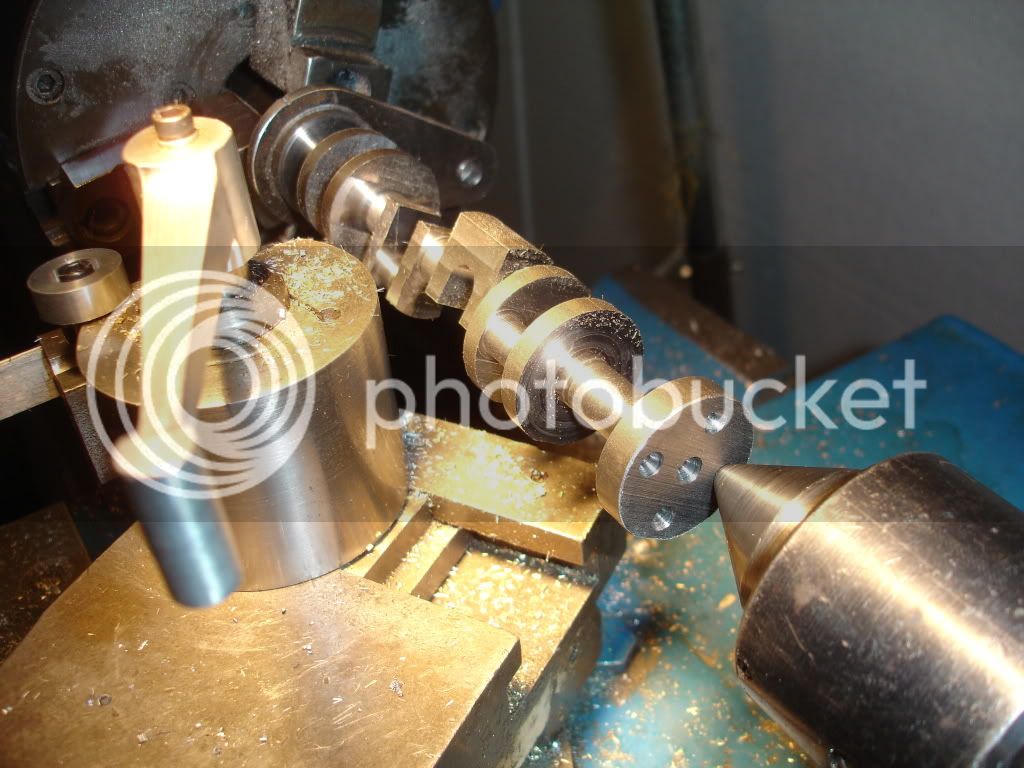
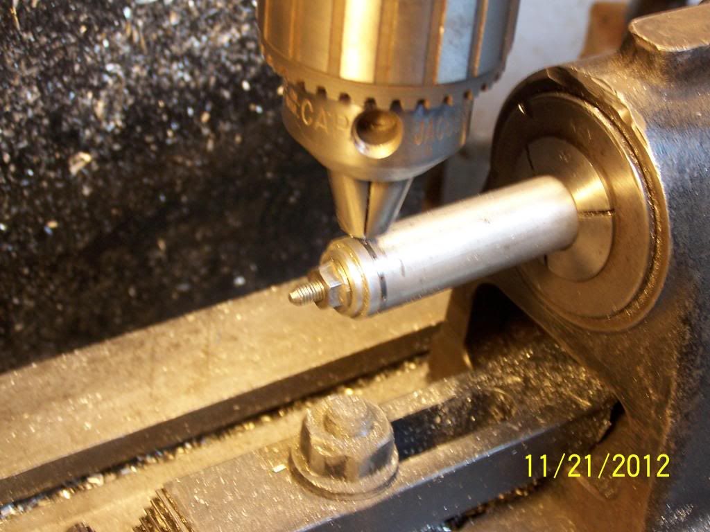
Its time to mount it in the lathe. I first placed a piece of bar in the chuck and turned a live center. I have a live center that fits in the spindle taper but I like the chuck idea cuz I think its more accurate, less likely to wobble.
DSC02111.jpg

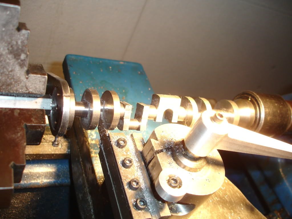
I rough in the main first.
DSC02110.jpg

Next I turned the throw pins to final size. The tool looks like a parting tool and it is but its been ground to more resemble a turning tool. The corners have been broken. Having a chamfer in the corners strengthens the crank. I'll releave the rods to allow for the chamfer.

I haven't been following this build, but will sure enough browse through the rest of the excellent progress achieved with this engine.

Curious to know how you were able to form the 5 centerbores on both ends of the crankshaft. How did you align it such to have the paired centerbores opposite of one another yet parallel along the axis?

Ian
 
"Curious to know how you were able to form the 5 centerbores on both ends of the crankshaft. How did you align it such to have the paired centerbores opposite of one another yet parallel along the axis?"
Thanks for the question. Answer is that within reason they don't need to be aligned cuz any misalignment gets turned out. To get them close though I first clamped the bar on the mill table and milled a flat on each end of the bar. I then stood the bar in the mill vise with the flat against the solid jaw, dialed in the center and center drilled the spots, flipped the bar end for end and did it again. Yeah, the bar was sticking up 6 inches.
 
Last edited:
"Curious to know how you were able to form the 5 centerbores on both ends of the crankshaft. How did you align it such to have the paired centerbores opposite of one another yet parallel along the axis?"
Thanks for the question. Answer is that within reason they don't need to be aligned cuz any misalignment gets turned out. To get them close though I first clamped the bar on the mill table and milled a flat on each end of the bar. I then stood the bar in the mill vise with the flat against the solid jaw, dialed in the center and center drilled the spots, flipped the bar end for end and did it again. Yeah, the bar was sticking up 6 inches.

Not sure how that would be ok. Wouldn't the crankpins be slightly off then? Wouldn't that then cause the pistons to be in the incorrect position in relation to each other? or is there a decent tolerance for engines?

Wow, that really does sound effective. Having that flat spot would prevent it from rotating out of position when flipping it end over end. Ingenious!


Ian
 
Not sure how that would be ok. Wouldn't the crankpins be slightly off then? Wouldn't that then cause the pistons to be in the incorrect position in relation to each other? or is there a decent tolerance for engines?

Wow, that really does sound effective. Having that flat spot would prevent it from rotating out of position when flipping it end over end. Ingenious!

Keep in mind, once centered between two center spots any throw pins turned will be on that centerline. The throw plates are slightly off but they get faced in the same operation so that brings them back on. I like to finish the mains last because I find having the 5 mains lined up is critical so any previous minor bending or warping gets turned out as a final operaton. Slight misalignments of the throws can be tolerated.
There's been lots of discussions on how to make mult-cylinder cranks. Its a tough project and lots of methods have been suggested. My method for sure is not the only workable solution but I will say if done carefully it gets the job done. For me the biggest advantage is using milling to remove most of the excess metal. I've tried lathing the whole thing. That's an exercise in frustration, at least for me. I've tried building up cranks from side plates and silver solder too. I've got single cylinder engines running that way. But with multi's,it's too tough for me to get the mains straight cuz the heat warps everything.

I'm open to other opinions. I'd be fun to hear other's experiences.
 
Last edited:
I've got to split the rings before heat treat. Clieving compression rings is easy but I'm bewildered about slitting the oil rings. Seems the oil rings don't clieve to neatly. Any suggestions?
 
I've got to split the rings before heat treat. Clieving compression rings is easy but I'm bewildered about slitting the oil rings. Seems the oil rings don't clieve to neatly. Any suggestions?


KBC tool has slitting/slotting saw blades as thin as .008 if you want to try to cut one
 
Sorry for the delay. Been busy.
Got back to the rings. Decided to turn the oil rings and cleive them first then fixture them up to reduce the center.
100_0617_zpsd027cdbd.jpg
 
Here's a pick of me drilling the oil holes. I found a #60 drill was hard to keep in the center of the groove so I ground the shank end into a spade bit, gripped it close to the chuck. it worked well.
100_0616_zpse2827cf3.jpg
 
Doing the heat treat. The thickness of the plate is important, about 1/8 inch. Turn the steel slightly dull red, remove the torch and let the ring cool for a minute or so. Getting it too hot is bad for warpage. To size the gap I grind it with a Dremel disc. I've tried filing them but end up too often breaking them. Place the tool in a vise, open the ring so the disc is in the gap and touch it to the wheel. Works well.
100_0623_zps08419def.jpg
 
Ahh, found the switch to editor mode. So here's a cylinder. Got the o-ring groove and o-ring in place. I used extra soft o-rings from McMaster-Carr. The plan is to seal the water jacket from the crankcase. Haven't yet tested it for leaks. I grease them up with Vaseline and slide the sleeve in. Seems to work.
100_0628_zps590a719e.jpg

100_0626-Copy_zps6bf0bc0b.jpg

The cut in the block upper right of the right sleeve is where the water passes up into the head. The head has a hole drilled full length taking the water back to the front of the head then into the intake manifold. The next post will show the intake in place with the goose neck screwed on.
 
Last edited:
Here's a pic showing the way the intake mates up with the heads. Notice the plug in the lower right end of the head. The water passage is blocked off by that plug. Water turns just inside the end of the head and routes up through the manifold and out the goose neck. The goose neck pipe was machined in two halves then glued together with J&B weld, which was then glued to the base flange. The pipe extends into the flange all the way to the manifold. The pipe id is 3/16 inch. The left head has the same passage. The flange screws are 2-56.
100_0630-Copy_zps2a575ff5.jpg
 
Last edited:
100_0631_zps41848bc6.jpg


This this is a picture of the gear cover/water pump base. The hole in the center is the water intake into the pump. The left and right holes are pump outlets directly to the block.
100_0634_zps63e4afc2.jpg

Here the pump is mounted. Hope it works. I'm worried about my shaft seal. Couldn't afford a seal for an 1/8 inch shaft so I drilled a length of teflon rod for a seal. We'll see.
 
Last edited:
I like this picture. Its a recent shot of the bottom end. It shows the bearing shells and the shaft tunnel. Look in the tunnel and you can see where the tappets will be contacting the cam. I used a ball end mill to mill the pockets for the crank. To save time I used a rather large scallop height. A finer surface would make for better pictures. I should have cleaned it for the picture. Its covered with Vaseline from sliding in the sleeves. Never the less, I like it.
100_0637_zpsb05d9bca.jpg
 

Latest posts

Back
Top