Understanding the flywheel governor

Home Model Engine Machinist Forum

Help Support Home Model Engine Machinist Forum:

This site may earn a commission from merchant affiliate links, including eBay, Amazon, and others.

Brian Rupnow

Design Engineer
Project of the Month Winner
Joined
May 23, 2008
Messages
14,969
Reaction score
8,250
Location
Barrie, Ontario, Canada
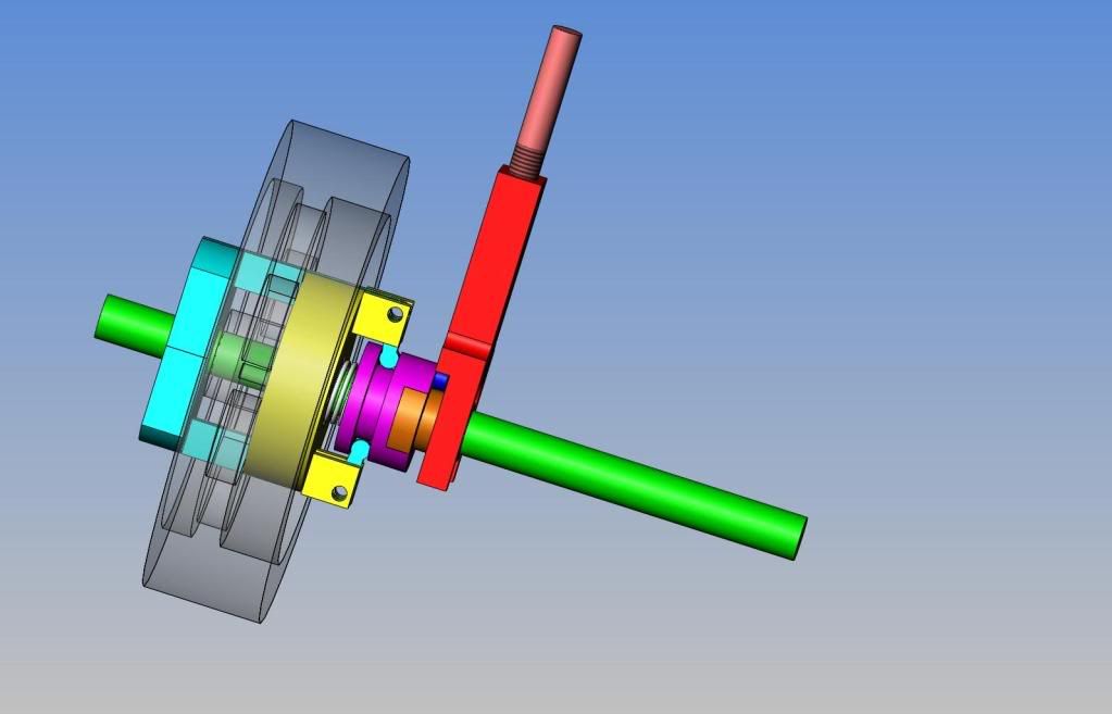
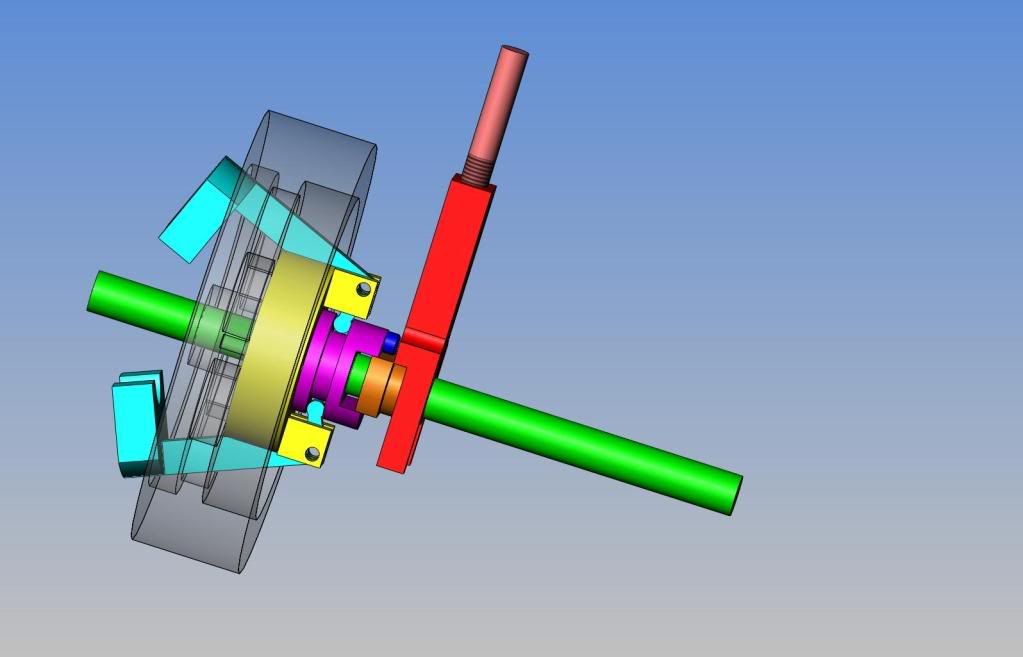
I have been studying on the flywheel governor that was posted by Putputman, Superfast, and partly by "Chuck". This is not an easy thing to get your head around. The purpose is to either engage the rod which opens/closes the valve which allows the engine to "fire" or not to engage it so that the engine only coasts. I had to model it all to get an understanding of what was actually happening there. In essence, at low speed, the compression spring holds the weights on the ends of the counterweight arms in close to the crankshaft, and the small "cam-screw" does interact with the valve rod and lift it up and down, allowing the engine to "fire". As soon as it fires, the engine revs up and centrifugal forcr forces the weights to fly out away from the crankshaft.--This in turn rotates the weight arms which the weights are soldered to to pivot, and pull the purple sliding ring in closer to the yellow disc which is bolted to the flywheel----this compresses the compression spring, and the purple sliding hub which has the dark blue "cam screw" attached to it slides closer to the flywheel so that the head of the "cam screw" no longer reaches the valve fork to lift it. Since the engine will not then fire, the engine slows down, centrifual force on the weights is not so great, and the compression spring expands and moves everything back into the "low speed" mode.
FULLASSEMBLYOFFLYWHEELGOVERNOR.jpg

FULLASSEMBLYOFFLYWHEELGOVERNOR-2-1.jpg

FULLASSEMBLYOFFLYWHEELGOVERNOR-1.jpg


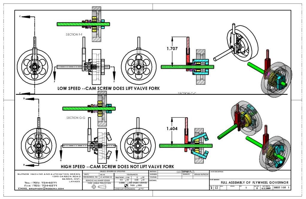
View attachment FULL ASSEMBLY OF FLYWHEEL GOVERNOR.PDF

FULL ASSEMBLY OF  FLYWHEEL GOVERNOR-1.JPG


View attachment FULL ASSEMBLY OF FLYWHEEL GOVERNOR-3.PDF
 
There is a very big, fundamental difference between the governor on a compressed air engine and that of a hit n miss IC engine.

On the compressed air engine, the governor weights control engagement and disengagement of the inlet valve. On a hit n miss IC engine, the governor controls the exhaust valve by holding it open when the engine is overspeed.

Another way to look at it is, on a compressed air engine, the governor prevents opening the inlet valve when overspeed, while on an IC engine, it holds the exhaust valve open when overspeed.

Chuck
 
cfellows said:
There is a very big, fundamental difference between the governor on a compressed air engine and that of a hit n miss IC engine.

On the compressed air engine, the governor weights control engagement and disengagement of the inlet valve. On a hit n miss IC engine, the governor controls the exhaust valve by holding it open when the engine is overspeed.

Another way to look at it is, on a compressed air engine, the governor prevents opening the inlet valve when overspeed, while on an IC engine, it holds the exhaust valve open when overspeed.

Chuck

Thanks Chuck---I "kind of" knew that, but I'm figuring some of this out as I go along.---Brian
 
An excellent explanation guys. This thread really helped me understand how
the hit and miss governor works!!

The drawings really make it perfectly clear.

Thanks,
Pete
 
10kPete---Sometimes when I am trying to figure out how a mechanism works, this is the only way I can do it. Model the individual peices, assemble them, then limit there movements to what they would be in a "real metal" assembly. I'm glad this was some help to you.----Brian
 
Brian,
What program are you using for your 3D models? I've used 2D AutoCad but never messed around with 3D stuff. The 3D AutoCad is, at least for me, almost impossible to deal with and I have never gotten very far with it.

Thanks,
Pete
 
I have always wondered why the governor on a hit and miss controlled the exhaust value instead of the intake valve. It seems to me that fuel would still be injected and then just pumped out of the exhaust port. Obviously there is a reason it works so what am I missing?

Pat
 
I've watched hit-n-miss engines running and tried to figure out how their governors were working and your drawings have been helpful. Thanks for the post Brian.

Cheers,
Phil
 
I have always wondered why the governor on a hit and miss controlled the exhaust value instead of the intake valve. It seems to me that fuel would still be injected and then just pumped out of the exhaust port. Obviously there is a reason it works so what am I missing?

Pat
Two reasons, if the intake was help open, the compression would be going out of the carb, and the possibilty of a backfire causing a real fire.
While coasting with the exhaust valve held open, the intake doesn't work as it is atmospheric, and there is no suction on the backstroke to open the intake valve, thus no fuel drawn in.
 
There is a very big, fundamental difference between the governor on a compressed air engine and that of a hit n miss IC engine.

On the compressed air engine, the governor weights control engagement and disengagement of the inlet valve. On a hit n miss IC engine, the governor controls the exhaust valve by holding it open when the engine is overspeed.

Another way to look at it is, on a compressed air engine, the governor prevents opening the inlet valve when overspeed, while on an IC engine, it holds the exhaust valve open when overspeed.

Chuck

Just to add to the mix - you can also regulate the valve cut-off on an air/steam engine with a flywheel governor.

GOV.JPG


AMES GOV.jpg
 
Last edited:
Two reasons, if the intake was help open, the compression would be going out of the carb, and the possibilty of a backfire causing a real fire.
While coasting with the exhaust valve held open, the intake doesn't work as it is atmospheric, and there is no suction on the backstroke to open the intake valve, thus no fuel drawn in.

I knew the reason would be obvious! Thanks Lance.
 
Brian, thanks for a better understanding of how they work, you make it sound so simple and look even more simple with the drawing, to master the drawing would be a wonderful thing in life would make building a lot more simple for the simpe like me, thanks again, copy and paste again, Lathe Nut
 
Thanks for opening the discussion here Brian, I actually understood the principle of the H&M governor but I don't know how to change the hysteresis. My engine governs but it does so very quickly so it does not sound the same as the real engines. It should have a greater speed variation between when it hits and when it starts to miss again.

Any ideas?

Jim
 
Thanks for opening the discussion Brian, I actually understood the principle of the H&M governor but I don't know how to change the hysteresis. My engine governs but it does so very quickly so it does not sound the same as the real engines. It should have a greater speed variation between when it hits and when it starts to miss again.

Any ideas?

Jim

To much tension on the weights will cause this, try lighter or longer springs. It's a very touchy adjustment even on a full size engine. I had to go to 1 spring on a 1 1/2 hp emerson brantingham to get it to cycle right.
 
Last edited:
Back
Top