Building a bigger Easton & Anderson Grasshopper

Home Model Engine Machinist Forum

Help Support Home Model Engine Machinist Forum:

This site may earn a commission from merchant affiliate links, including eBay, Amazon, and others.

Jasonb

Project of the Month Winner!!!
Project of the Month Winner
Joined
Mar 30, 2008
Messages
3,767
Reaction score
1,239
Location
Surrey, UK
Some of you may have seen in the past me mention myintension to build this engine in a bigger size, well I’ve started.

It will be based on the 1/12th scale model byAnthony Mount that was serialised in EIM and also reproduced in his secondbook. Plans are also available from BruceEngineering as well as castings.

I intend to double the size to 1/6th scale and havingrecently obtained some photos of the original engine will try to make minetruer to that. This will result in an engine with the following spec.

Length 15 ½”

Width 10 ¼”

Height 14”

Flywheel dia 10 ¾”

Bore & stroke 1 7/8x 2”

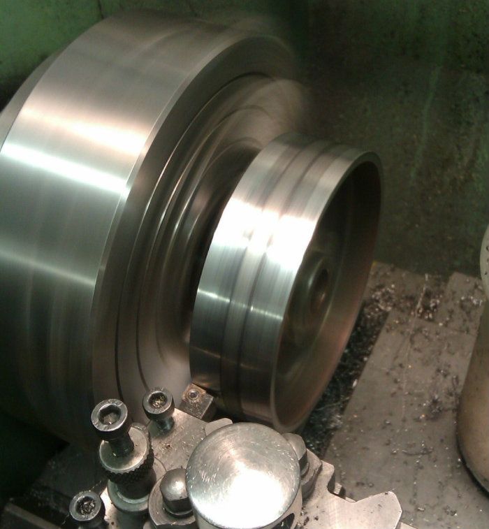
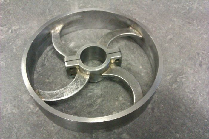
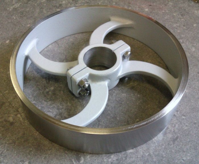
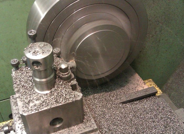
The prototype was quite a small beam engine, most peoplethink of the large waterworks pumping engines when a beam engine is mentionedbut this one was smaller and would likely have been used in a mill or factoryto drive overhead line shafting. That’s why it can be built at a relativelylarge 1/6th scale and still fit the flywheel on my lathe (just).
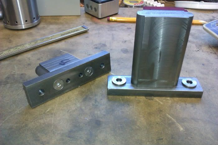
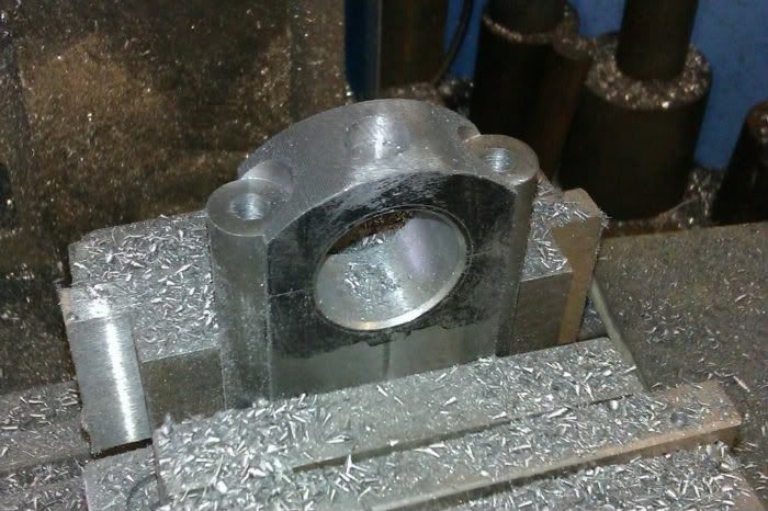
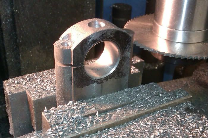
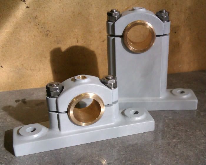
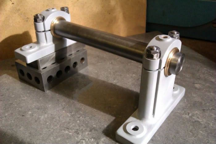
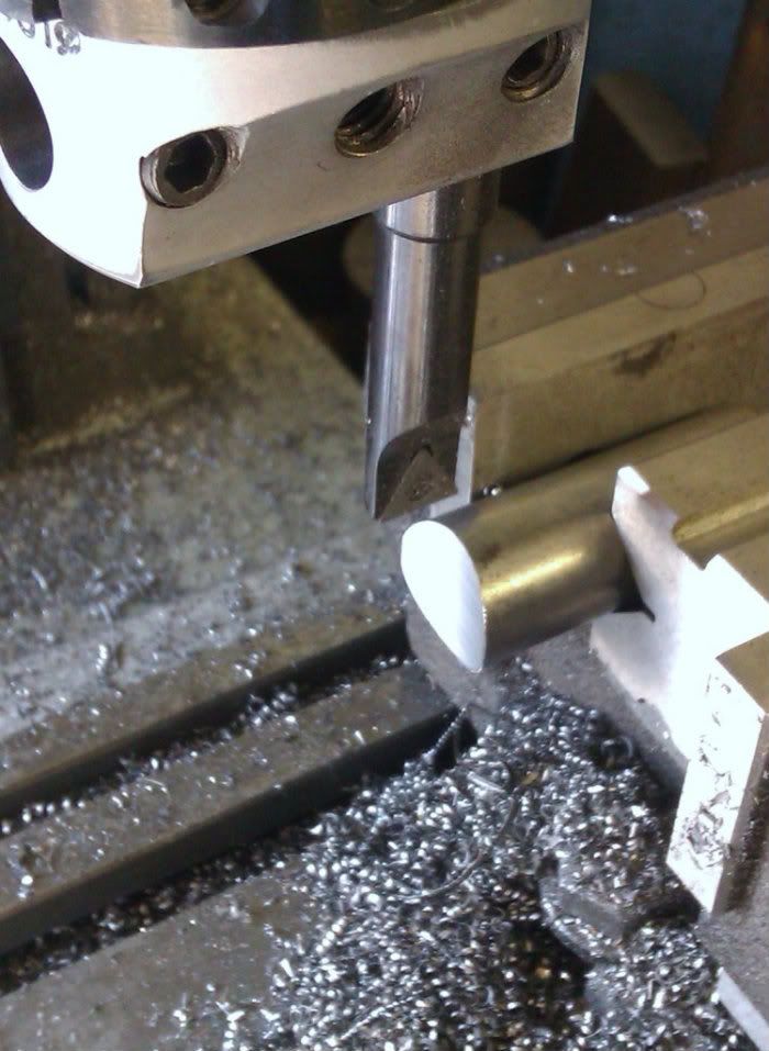
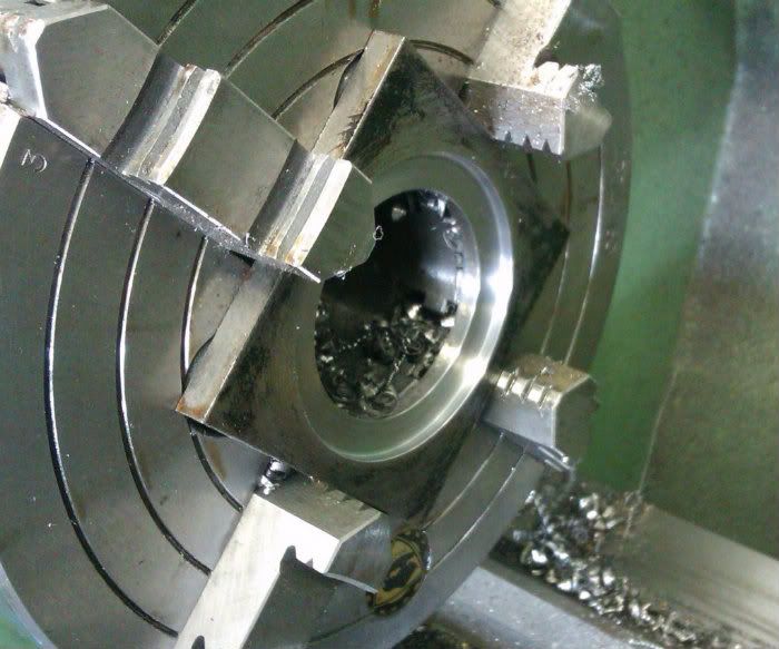
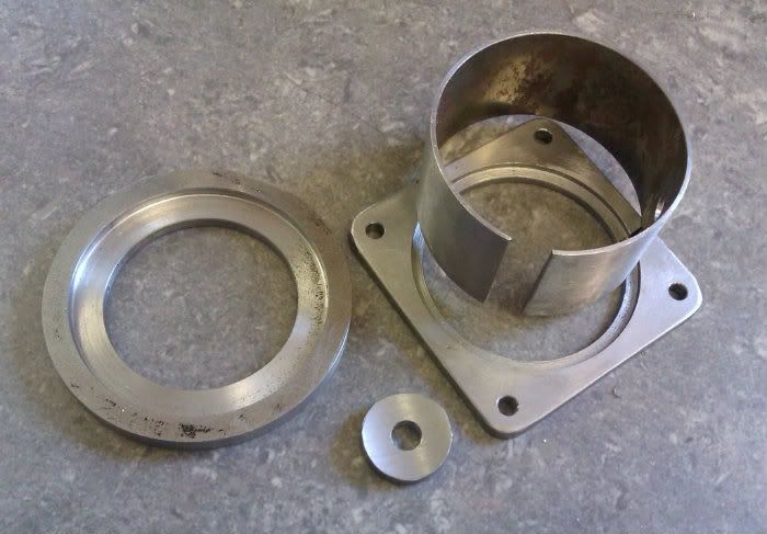
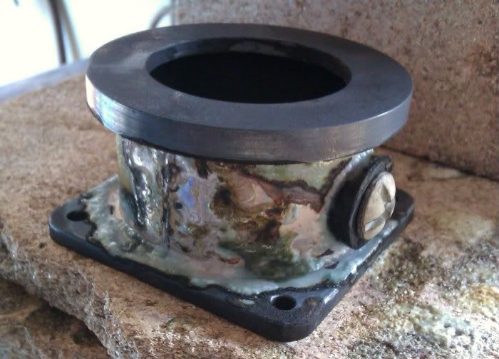
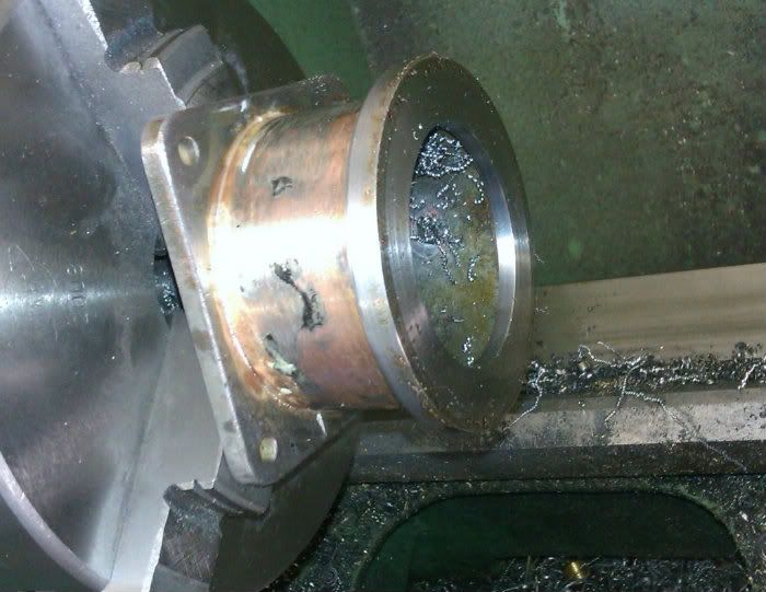
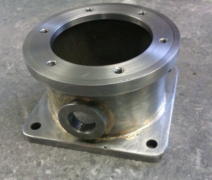
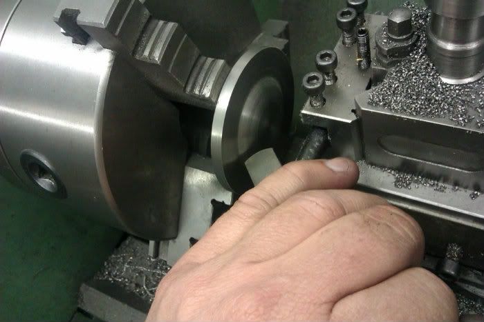
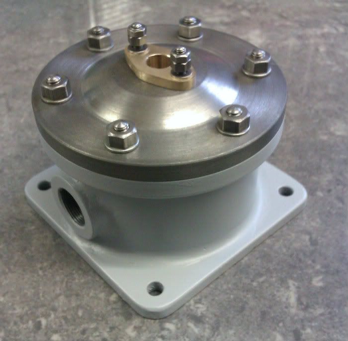
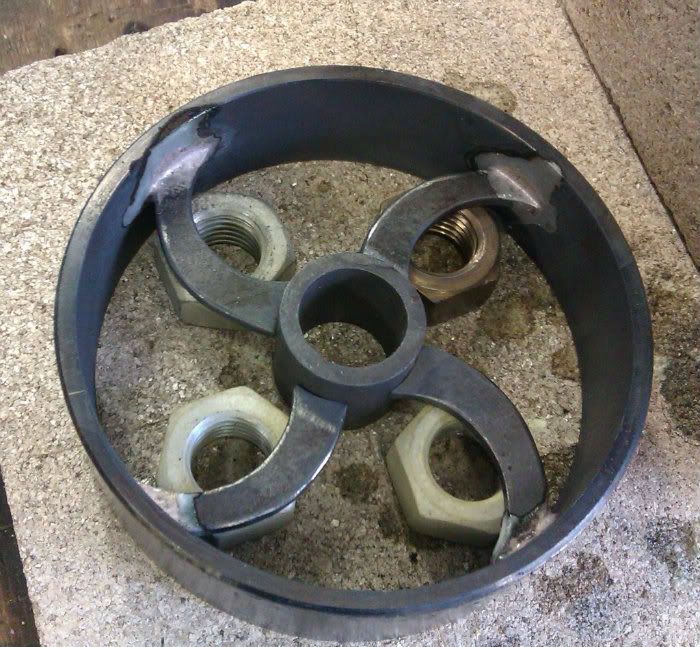
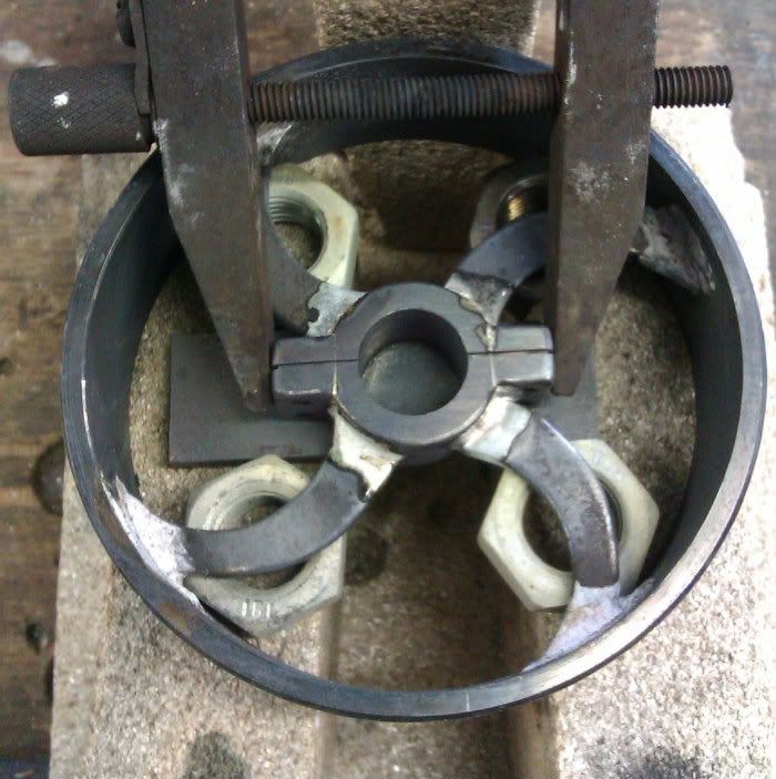
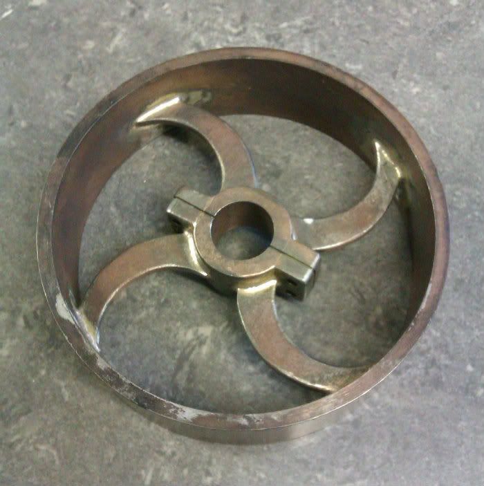
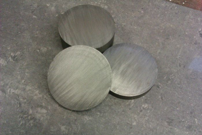
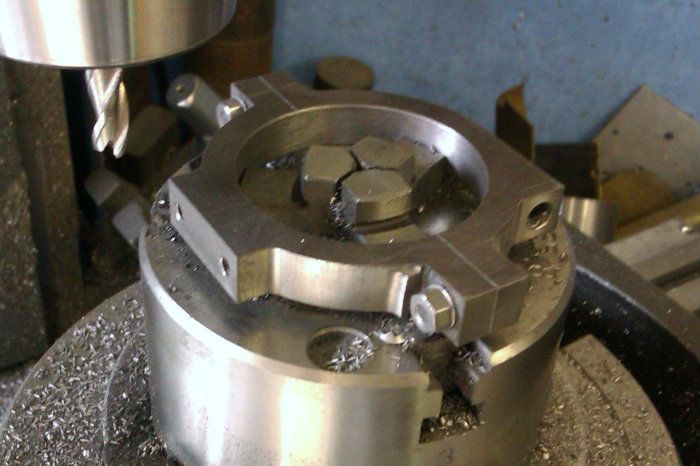
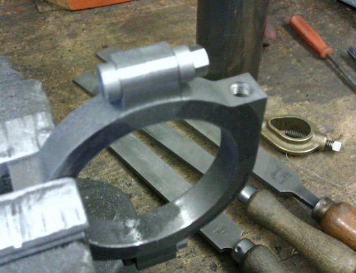
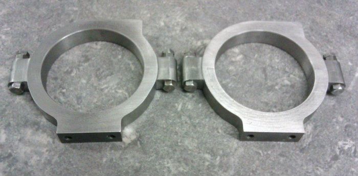
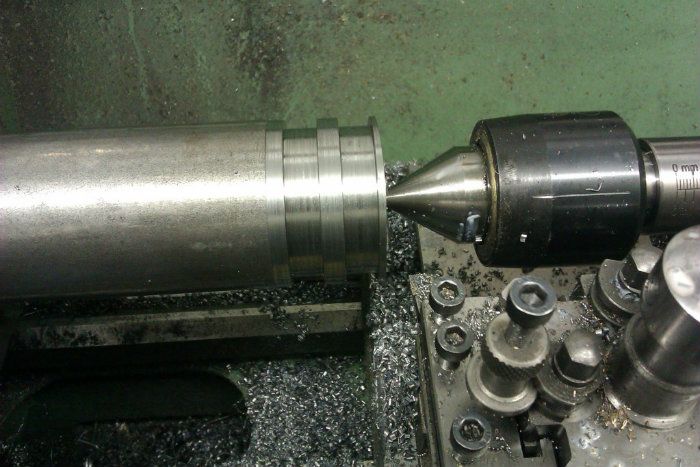
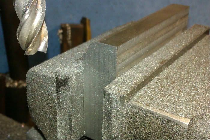
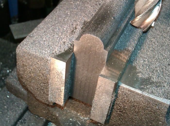
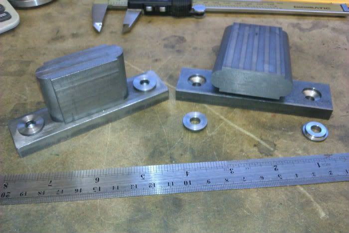
I probably won’t do a bit by bit build but just show some ofthe more interesting parts which will mostly be the fabrication of the itemsthat are supplied as castings in the Bruce model and anything else that I thinkothers may be interested in.

Grasshopperengineframeend.jpg


Grasshopperengineframeend.jpg


J
 

I’ll make a start with the two crankshaft pedestalls, theseare basically the same except the outboard one is longer to compensate for notsitting on the engines base casting.

I started by machining some cast iron block to 2” x 11/16”section then mounted it on its side in the mill vice and using the ARC functionon the DRO cut a ¼” radius quadrant with querk on one edge.
IMAG0786.jpg


And then the opposite edge
IMAG0787.jpg


The same process was carried out on the other edges until Ihad two embryo pedestals, the bases were cut to 4” long from 1x3/8 flat steeland drilled for mounting bolts and small discs added for a raised “cast” areaaround the hole.

IMAG0788.jpg


The CI blocks were then drilled and tapped so they could bescrewed and loctited to the bases, Yes there is a place for socket head screwson period engines and that place is out of sight;)
IMAG0789.jpg


Once the loctite had set I could locate the bearing heightsfrom the base of the fabrication and using the boring head these were cut to7/8” dia, note the plug gauge in the second photo used to ensure the holematched the already machined bearings.
IMAG0792.jpg

IMAG0794.jpg


This work was done before I got the photos of the originalfrom which I can see that the bearings should have had flat tops but I’ll stickwith a bit of artistic licence. The tops were radiused using the ARC functionagain.
IMAG0796.jpg


Then a ½” endmill was used to cut flats for the nuts to seaton and a 3/8” hole bored for a boss to take the oil cups. Holes were drilledfor the studs, clearance down to the ctr line and tapped below.
IMAG0798.jpg


A slitting saw was the fitted and used to split the blocksin two.
IMAG0801.jpg


A bit of hand work was then required to round off all theexternal corners to help get that cast look.
IMAG0807.jpg


Followed by an application of JB Weld and plastic metal tofillet all the internal corners.
IMAG0820.jpg


While that lot set I machined up some 1BA studs, washers, nutsand locknuts. Finally the filler was smoothed off and a coat of primer sprayedon to see if the filler looked OK, I think it did.
IMAG0823.jpg

IMAG0824.jpg


J


That's looking good Jason, I will follow you on this if you don't mind, I need the knowledge and will enjoy the journey.

Jim
 
  • Like
Reactions: gus
Following you and learning as you progress.

Vince
 
  • Like
Reactions: gus
A very nice looking engine with some challenging fabrication. Look forward to seeing how it goes.
 
  • Like
Reactions: gus
Your old fashion Bearing Pedestals brings back 1949 memories. In our neighbourhood no customers believe in ball bearings. Steam operated sawmills prefer Pedestal Bearings with oil sump and a hung oil ring that brings lube oil on the shaft and bearings.
Overhead drive pulleys would same bearings with oil top up yearly.They don't run dry.

Your bearing pedestals are very well made. Truly a great craftsman.
 
A really great build Jason. Please keep the photos coming
 
The cylinder top cover started as a disc sawn off a length of 80mm dia cast iron bar, this was held in the outside jaws and the internal spigot formed.

IMAG0821.jpg


It was then revered in the chuck and held by the spigot while the top profile was machined I copied the shape in the photos rather than that of Anthony Mount's (AM from now on) design, the curve was done freehandand then fine tuned with a file.

IMAG0828_zps96c0df7f.jpg


Then over to the mill and the centre was located

IMAG0829_zps578bb923.jpg


The PCD function on the DRO was used to place the stud holes around the edge and the ones for the gland studs. I found on the Benson that if I doubled up the fixings then they seemed too big so on this engine I will be going buy what looks right rather than just double the size of everything.

IMAG0830_zps1f53150c.jpg


The photo of the full size suggests there is a recess in the top of the piston rod packing gland to catch oil from the drip feed oiler so this was added rather than a plain gland as per AM's drawings. I like to make the studs and fixings as I go along so here it is done.

IMAG0831_zps712bf3f6.jpg


J
 
The prototype has a large air pump that would have blown cold air through a condenser, this can be made as a working pump or a dummy, I'm going to do the dummy at the moment but may add some internals at a later date.
I was in two minds whether to machine the pump body from a solid lump of 40mm cast iron block or fabricate, as this will be a heavy engine when done I opted for fabrication as it will be a bit lighter. A rummage around failed to find a suitable bit of 3/16" plate for the base flange so a few offcuts were welded together and then machined to give the required 2.5" square followed buy boring out for the tube with a boring head.
IMAG0836_zps638073cc.jpg

While the boring head was set to the correct dia I used it to flycut the end of a 3/4" bar to form a boss for the air pipe.
IMAG0838_zpse2406873.jpg

The top flange was cut from 1/4" plate and a stepped hole bored in the lathe, then holding by this hole the outside was turned round but left a little oversize.
IMAG0837_zps0732c7a4.jpg

The tube that goes between the two flanges was made from some that was a bit too big in diameter so I worked out what needed to be cut from the circumference and cut out the waste. Here you can see the parts ready to be soldered together.
IMAG0839_zps35a927a1.jpg

And after silver soldering
IMAG0840_zpsd8740900.jpg

After sitting in the pickle while I watched the F1 qualifying and a quick scrub the assembly was put back on the lathe and the top flange turned true to the base and to final size of 2.5" dia x 7/32" thick.
IMAG0842_zpsab919e07.jpg

A bit more cleaning had it looking like this after which I added JB weld to all the internal corners to get that filleted cast look and left it overnight to harden.
IMAG0843_zpscc1fbd96.jpg

While the JB Weld was going off I made the top cover, very similar to the cylinder cover but as the curved top which is not shown on AM's drawings runs right down to the flat bolting surface it was not ideal to use a file to refine the shape without marking the flat face. Solution was to hold a bit of bar in the tool post to act as a rest and then hand turn the curve, this posed photo will give an idea of how I did it with a woodturning scraper.
IMAG0844_zpsd1afe723.jpg

This morning the JB Weld could be smoothed off and a bit of primer added, then machine the gland and screw it all together.
IMAG0847_zps8e755f5f.jpg
 
Next up was the pulley that would have taken the drive from the engine upto overhead lineshafting via a flat belt. The photos show a few differences between the original and AM's interpretation such as 4 spokes vs 6, a split clamped hub and a narrower rim.

I started with the hub, a bit of 1" bar was drilled 1/4" and parted off then two shallow 3/8" grooves milled in opposite sides to take a couple of lengths of 3/8" sq bar

IMAG0855.jpg


The three parts were silver soldered together then drilled for the clamping bolts after which they were cleaned up and all edges rounded off. I subsequently drilled the hub out a bit under finished size so there was less metal to heat up on the next soldering stage.

IMAG0856.jpg


I drew the pulley out full size on a bit of paper and used that to determine the positions of the various arcs to form the spokes. These were then marked out on some 1/8" sheet and cut & filed to shape, testing against the drawing for fit.

IMAG0864.jpg


A nice man on e-bay provided some 100mm OD x 4mm wall EWR tube and a suitable length was sawn off, the ends were tidied up overlength on the lathe.

IMAG0866.jpg


When heating the rim of a flywheel or pully it tends to expand which can make the gap between rim & spoke too large for the solder or pull against the hub and distort the finished item when it cools. I decided to solder in two stages, the first being the spokes to the rim. Each spoke was set on a nut to pack it upto height and an off cut used as a makeshift hub, the spokes were then solderd into place.

IMAG0867.jpg


A quick clean up of the inner spoke ends and the hub was set in place with a toolmakers clamp to ensure the previously soldered lugs would not move. This way I could heat the hub and not have the rim expand.

IMAG0868.jpg


And here it is after a dip in the pickle and a light wire brush to remove flux.

IMAG0870.jpg


Back to the lathe held it by the inside of the rim to bore the hub true and profile the rim to a slight crown. If you look at the lines on the rim you will see it is in 5 sections, the middle is parallel to the lathe axis, the ones either side of that are at 1deg and the outer section at 2deg, these will be blended later into a shallow crown.

IMAG0873.jpg


And here is the finished pully, you will see that before soldering I added a 1/64th slot 0.040" deep around the middle of the hub to look like a dummy split line.

IMAG0892.jpg


Just a little work to clean up the solder fillets, coat of paint and then mount on an arbour to blend the rim and thats another part off the list.

IMAG0893.jpg


J
 
Very nice.Thanks for sharing.

Ian (seagar).
 
Jason. I am really enjoying this. The photos and craftmanship are superb
 
Nice tutorial. I really like the use of JB Weld to make the casting look, I must try that!

Lee
 
Thanks for all the kind comments, now can you tell what this is yet?

IMAG0895.jpg


Two discs were cut off my ever shrinking piece of 80mm dia cast iron bar by hand to approx 1/2" thick and are to become the eccentric straps. These were then poped into the lathe and faced off to give a finished thickness of 3/8".

IMAG0897.jpg


I then did a quick bit of layout with a pencil to see roughly how much I could take off to get a flat reference face, this and the next few stages were all done with the discs held vertically in the mill vice and cut with a 1/2" endmill.

URL]


With the reference face established the discs were blued and marked out with the height gauge and the four extremities cut, you will notice I have left an 1/8" strip in the middle to allow for cutting and cleaning up the face.

IMAG0900.jpg


The flat faces for the bolts were then machined and some of the waste removed just by eyeballing clear of the line. The holes were also drilled at this setting. In addition I formed a flat to screw an oil cup into, these can be seen on the original photo but are not on AM's drawings

IMAG0901.jpg


The discs were then cut in half with a hacksaw and machined back to the line, the socket head screws are only there while there is more machining to be done.

IMAG0902.jpg


The centres were marked and the strap mounted in the 4-jaw to bore the hole to 1 3/4".

IMAG0904.jpg


They were then held by this hole on the rotary table to clean up the outside profile using a 1/4" FC-3 cutter

IMAG0905.jpg


I then knocked up some filing buttons to round off the bolting lugs, quick tip when doing this the nut often works loose so give it a quick tap with a hammer which makes it slightly oval and it won't come loose again.

IMAG0906.jpg


Add a couple of fitted bolts, nuts & locknuts and thats them done save for a bit of clean up before final assembly.

IMAG0907.jpg


Any one want to guess what percentage of the original discs ended up as swarf? answeres in a day or two.

J
 
As always Jason, this is going to be a first class model. Castings are becoming less and less important in the days of JB weld!

Are you in the UK and if so are you going to the midlands exhibition next week?
 
Are you in the UK and if so are you going to the midlands exhibition next week?

Yes and No

Its a bit close date wise to Sandown and as I;m only 1/2hr away from there thats where I will be going.

J
 
Hi Jason
Fabulous work on the pulley as usual
inspiring!
Pete
 
With the eccentric straps done the next logical parts were the sheaves, they were roughed out from 2" bar when taking a break from sawing off the CI for the straps.

IMAG0894.jpg


With the straps completed they could be used to test fit the final sizing of the sheaves, I then parted them most of the way through finishing off with a hacksaw.

IMAG0910.jpg


Then poped back in the lathe and using the soft jaws they were faced off to finished thickness

IMAG09124.jpg


The throw was then marked out and punched with the optical punch and once clocked true in the 4-jaw the hole was bored.

IMAG09122.jpg


Just a couple of grub screw holes to finish them off and here they are with their straps.

IMAG0921.jpg


Jason
 

Latest posts

Back
Top