Elmer's #8 scotty - my second engine

Home Model Engine Machinist Forum

Help Support Home Model Engine Machinist Forum:

This site may earn a commission from merchant affiliate links, including eBay, Amazon, and others.

basement_guy

Junior Member
Joined
Sep 29, 2012
Messages
51
Reaction score
14
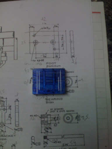
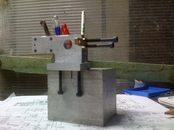
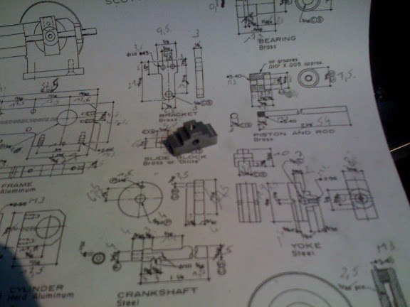
After building the easy engine. I would like to build Elmer's #8
I'm still wet behind the ears so any comment, advise is welcome.

I searched the forum and found interesting stuff.

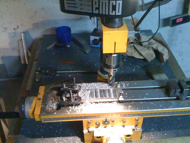
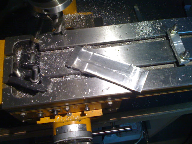
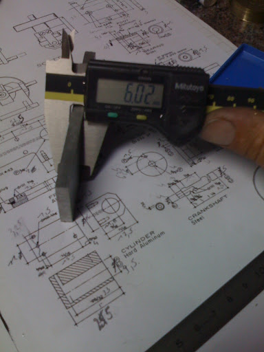
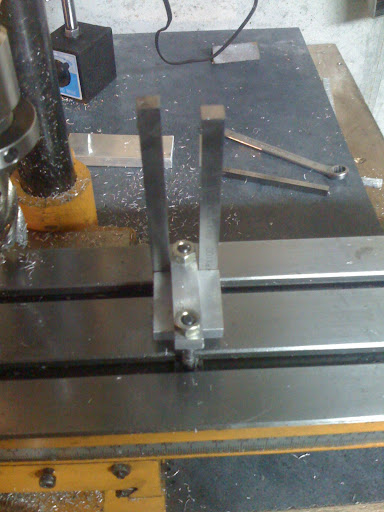
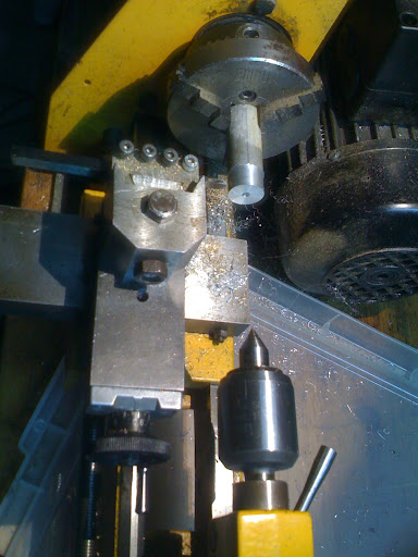
Anyway, here is my build log.
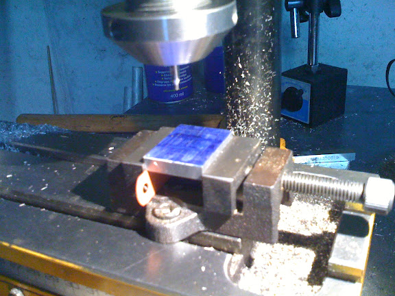
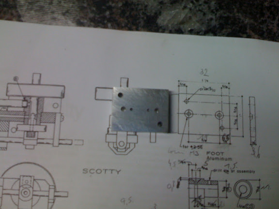
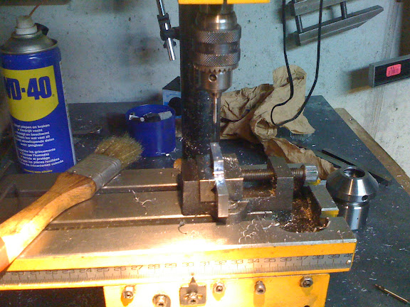
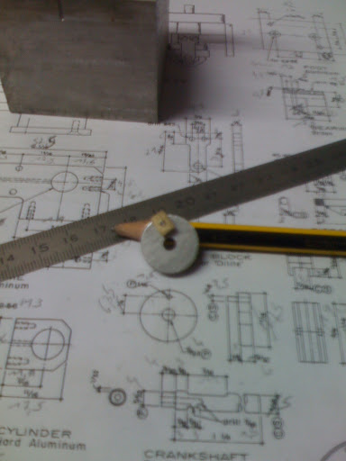
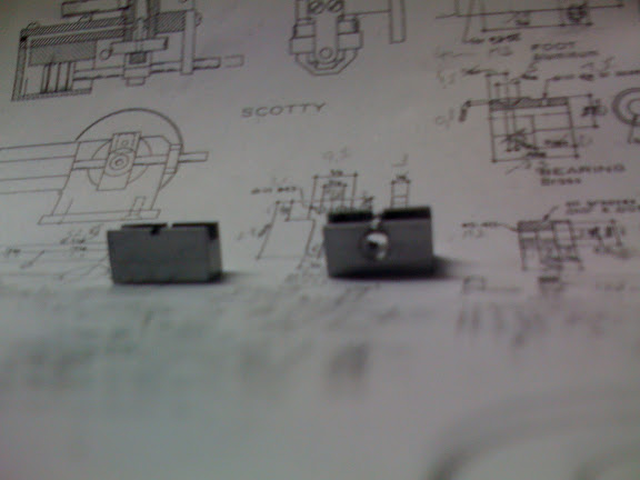
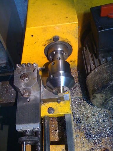
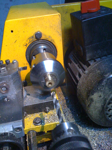
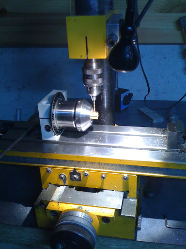
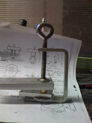
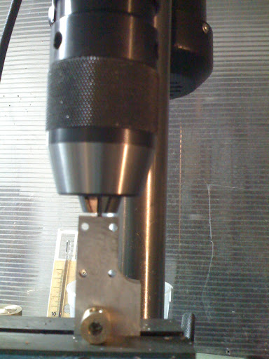
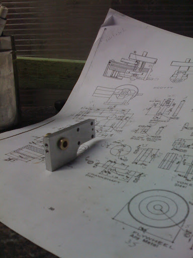
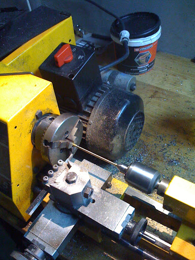
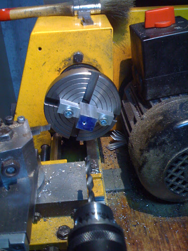
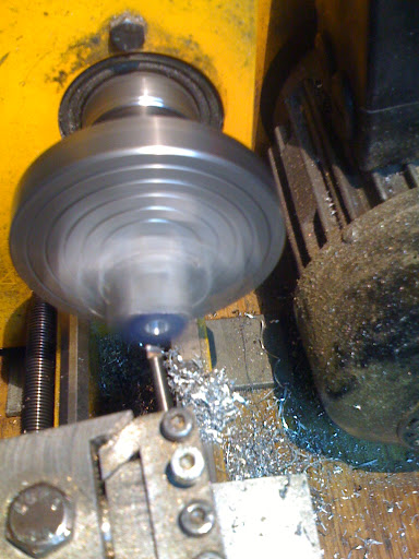
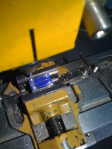
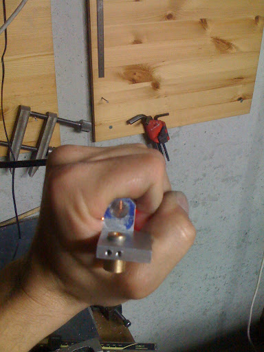
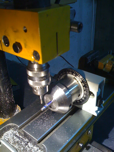
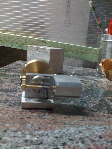
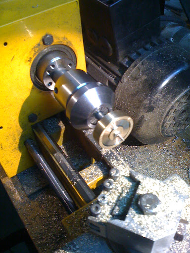
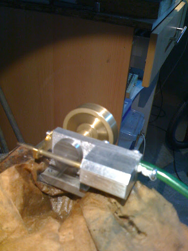
This is the first and second part I have made.

IMG_0529.JPG

IMG_0531.JPG


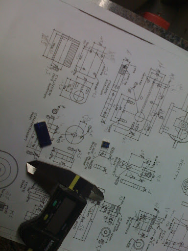
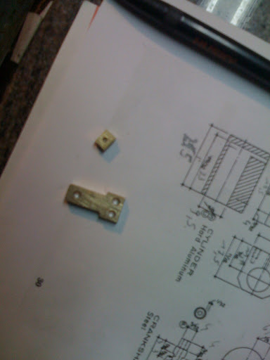
The quality of the pics is worse than the quality of the parts ;)

edit: resize pictures
 
I use material that i found in the scrapyard.
The smallest plate aluminum i found was 10mm. For the base and frame i only need 6mm.
This is how I resized it.

IMG_0533.JPG

IMG_0536.JPG


IMG_0537.JPG

This plate will become base and frame.

I have a limited selection of tools. This creates sometimes extra challenges. :)
 
Today i finished the base.
First i hacksawed the large plate into base and frame.
This pic is taken after i made the short side according to drawing.
The toolbits fit exactly in the millingtable slots. So I was sure to make a square part.
IMG_0539.JPG


The part is ready for drilling
IMG_0540.JPG


I use the scribed lines as reference. The exact position is made with the coordinate table.

IMG_0541.JPG


The part finished. I have made some extra holes on a wrong location. Lucky for me they will be covered or on the underside. :cool:

IMG_0542.JPG


I have to adapt the plans to the metric system. I adjust sometime to mach my tools. My smallest tap is M3.
And I make the baseplat 6 instead of 3
 
Your doing well,keep up the good work.
Ian(seagar)
 
You are doing fine.Like you, I started off with Elmers in 2004 and went on to build many engines. 8 years down the line I am still green with new and more complex engines. The slide valve engines takes a bit of cunning to built but very forgiving if you make mini errors. My last engine-------Glow Plug I.C. Engine was a near disaster now a collection item on my PC desk.Plan to build another same engine now that I know where I goofed.
 
Thanks for the positive comments.

Today i completed the frame.
In the pic; pilot drill, drill and tap in the same setup.

IMG_0543.JPG


checking the fitting of the parts and here is the first challenge.
My smallest tap is M3. As you see in the picture, the bolts to fit the bracket will interfere.

IMG_0546.JPG


I:D'm happy with the result so far.
 
I made the part without a name. I call it the drivingwheel. Tha material is not specified. I made if out of aluminum. The hole for the pin is drilled. In the slide block is reamed. The pin is steel.
The pin is pressed inside the drivingwheel. The slidingblock turns fee on the pin.

I had a hard time making the pin. The first 2 bended when i was neer the corrcect diameter. The reason was my toolbit was not exact on centerheigt. After i adjusted that it went without problem.


Ready to cut the drivingwheel
IMG_0547.JPG


the result

IMG_0551.JPG
 
I started working on the yoke. But i was untidy in my writing. I read 5 where there was a 3. This is the result, next to a new part ready for drilling.

IMG_0561.JPG
 
Today I completed the yoke.
I drilled and reamed the hole for the rod.
Drilled and tapped the other hole M3.
I have no 4jaw chuck so i milled the sides instead of turned.

IMG_0565.JPG
 
today I started making the bearing.
I had a piece of brass with diameter 12 in the 3jawchuck.
Brought it down to the correct diamters en parted it of.
Soon I realised I forgot to drill the part.
I took the collet holder and fixed that onto the lathe, checked runout (0.03mm) and drillid it.

IMG_0581.JPG

IMG_0582.JPG
 
I comleted the bearing.
IMG_0587.JPG


With a little help it fits into the frame.

IMG_0589.JPG


Now commes the scary part. Drilling the long hole.
I started very good. With a lot of up and down and cutting fluid.
At a sudden moment i came to the limit of the mill. It was not longer possible to lower the drill. I figured if i lower the head i can lower the drill again. But then the drillbit wil never come complete out of the hole.
I was almost at the point where the bearing started so i took the risk but should have know better...
Of course the drillbit broke with a long part left into the frame. :wall:

A new frame has to be made. And a new attempt to drill the large hole.
 
The new frame is ready.
I managed to drill the long hole. This time i driled it with the drill press.
IMG_0595.JPG


In a moment of inattention (I blame the morning shift waking up at 4o'clock) ) i drilled the small port on the wrong side.
This is not really a problem. Now I make a mirror of elmer's #8. :cool:

IMG_0599.JPG
 
Mirroring is no problem at all as long as the bearing is also mirrored. If not, you can plug the small port with a press fit and redo on the other side. If you go this route I would use the first port as a guide and drill out the second from the inside to save the effort of locating it again.

Thayer
 
Hey Thayer, the bearing is already on the "wrong" side. So it will be a special scotty.

I've made some progress.
This is the piston rod. Not threaded yet.
I made the final cuts with a parting off tool. That gives a good finish.
2012-10-18%252015.19.20.jpg


I started the cylinder. I have no 4jaw chuck so I made block (not 100% parallel) to clamp the part on the faceplate.
It needs hard hitting with a hammer to move so i think low speed boring small steps will be no problem.

2012-10-22%252010.21.32.jpg

2012-10-22%252010.38.02.jpg
 
Tee slotted face plate to hold job piece. Good idea.
I have seen 30 ft O.D. faceplate with move able clamps. The facing lathe and face plate were DIY.Owner also had a foundry.
The faceplate was cast in four quardrans and hand finished but faced finished mounted on same lathe.

He charge S$3000 for 10' O.D. simple facing jobs and S$9000 for 30' jobs.Good money but each job takes 2----4 weeks.
There were jobs qued outside his machine shop .Looks like he has 12 months of contract on hand. There are no machine shops with this size lathe.
 
This is the piston drilled and tapped.
2012-10-23%252020.39.29.jpg


I mounted the cylinder to the frame to check the holes. I hold a light in front of the long hole and there is a light in the cylinder!
You can see I also milled the edge of the cyliner.
2012-10-23%252021.08.18.jpg
 
I made the piston and fitted it to the rod.

Here I make the ports in the crancshaft. This was the first time i used the dividing head.

2012-10-27%252013.28.39.jpg


Time to test fit the parts. (the flywheel is not yet ready)

2012-10-27%252018.56.11.jpg


Looking good so far. :cool:
 
It is running!

2012-10-29%252020.59.32.jpg


There is still some work to do to make it look good.
 
  • Like
Reactions: gus
Back
Top