Wyvernish Build

Home Model Engine Machinist Forum

Help Support Home Model Engine Machinist Forum:

This site may earn a commission from merchant affiliate links, including eBay, Amazon, and others.
I really enjoyed the local engine show this weekend, got things all put away and just barely got enough time to get a post in.

 
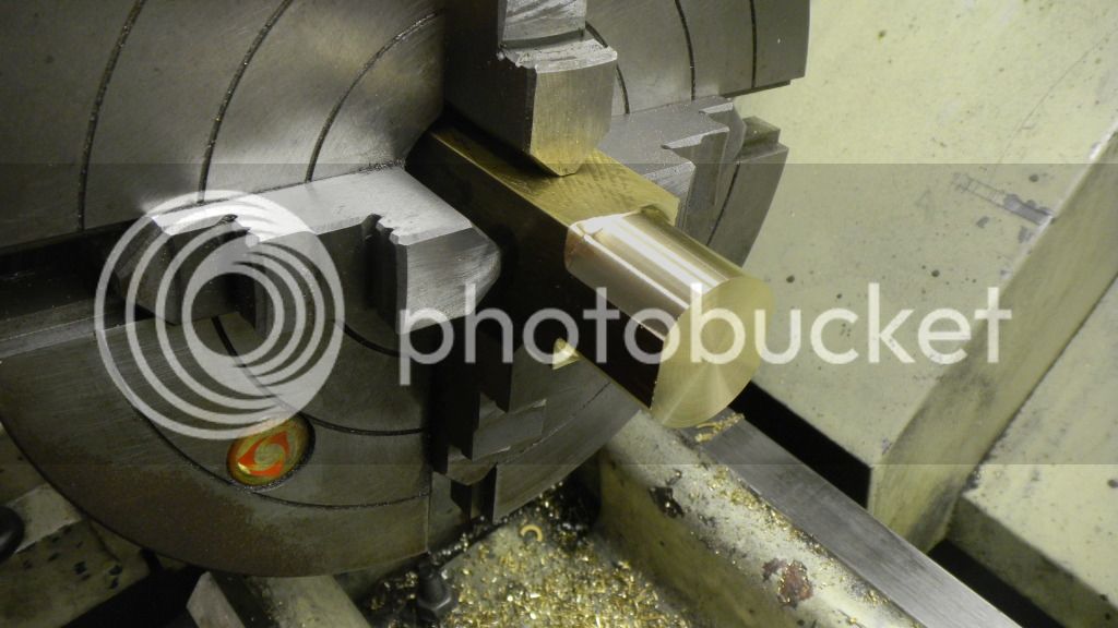
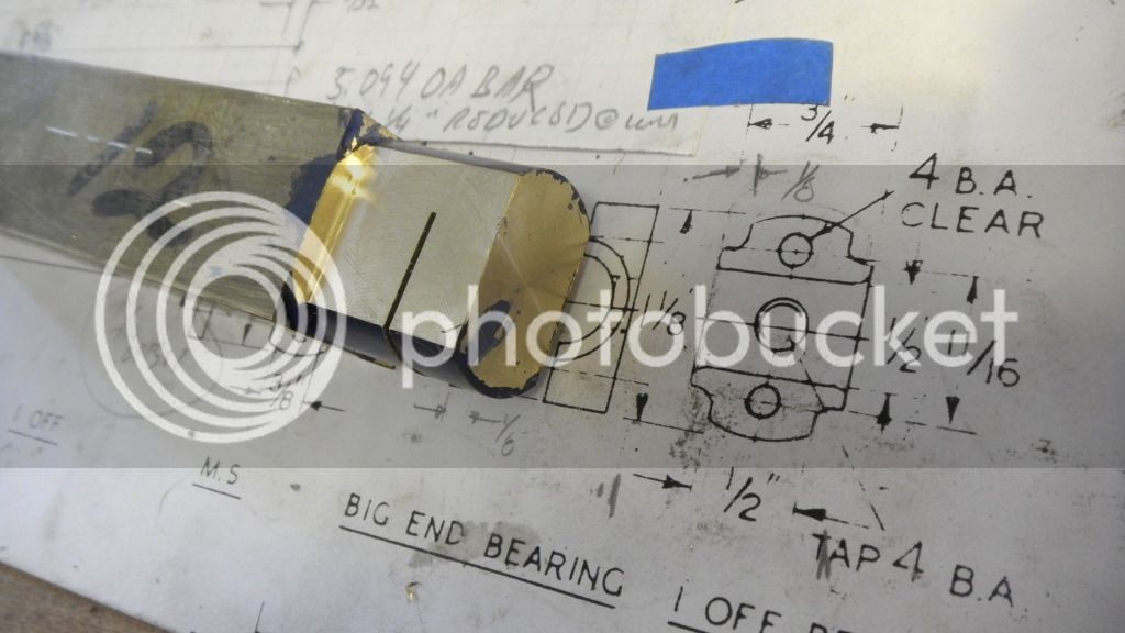
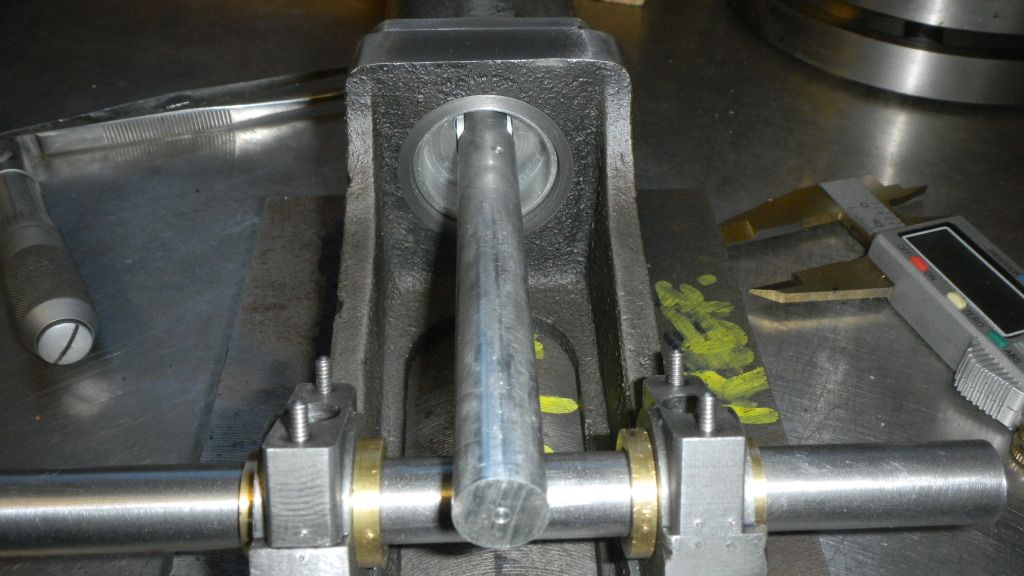
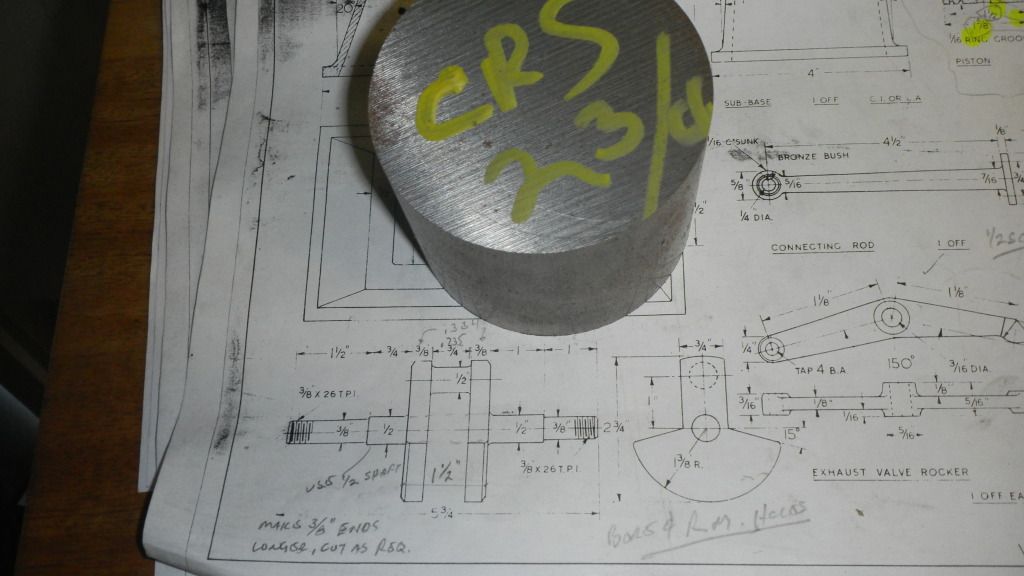
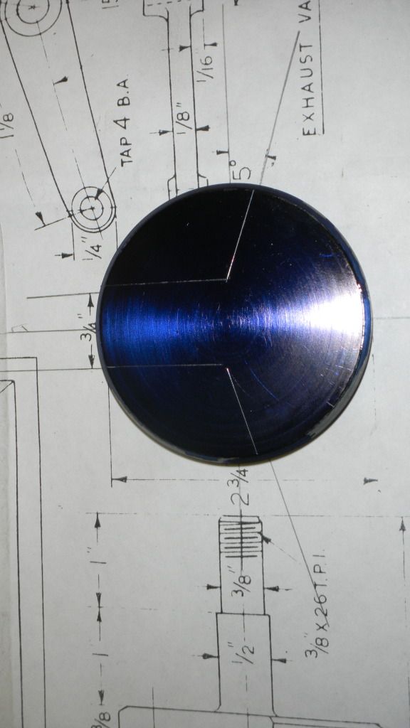
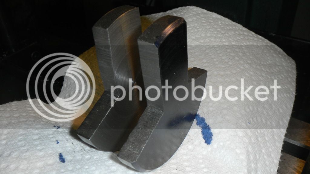
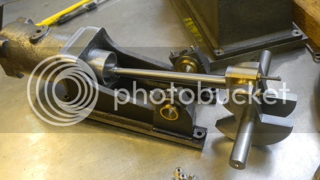
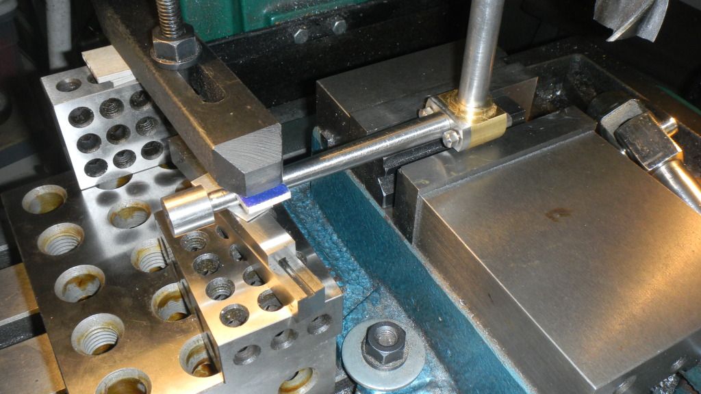
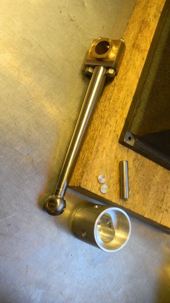
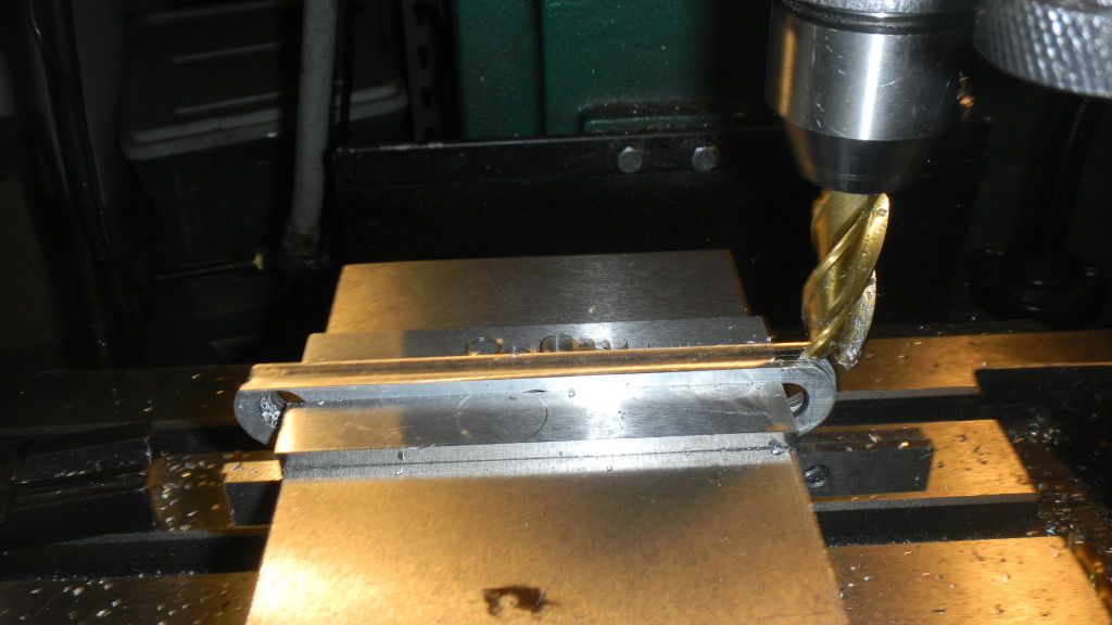
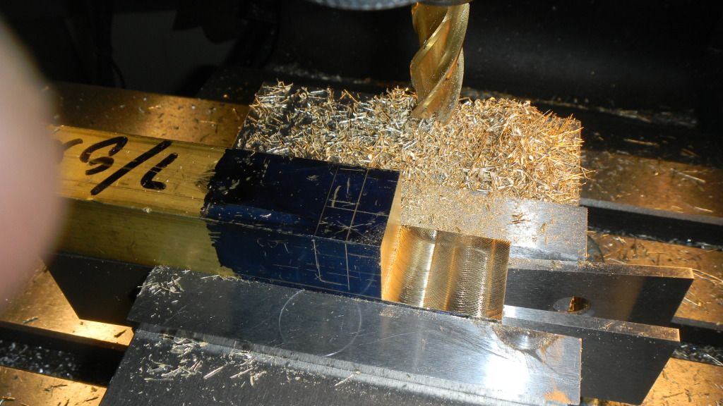
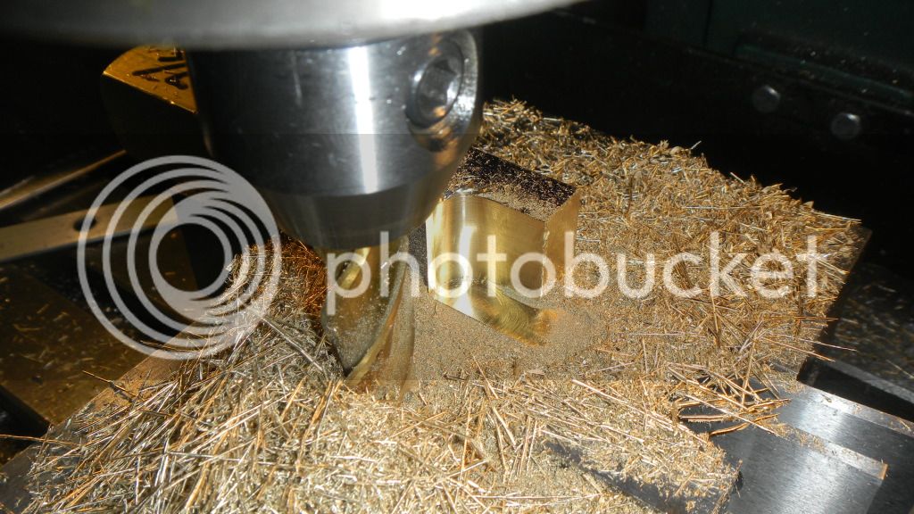
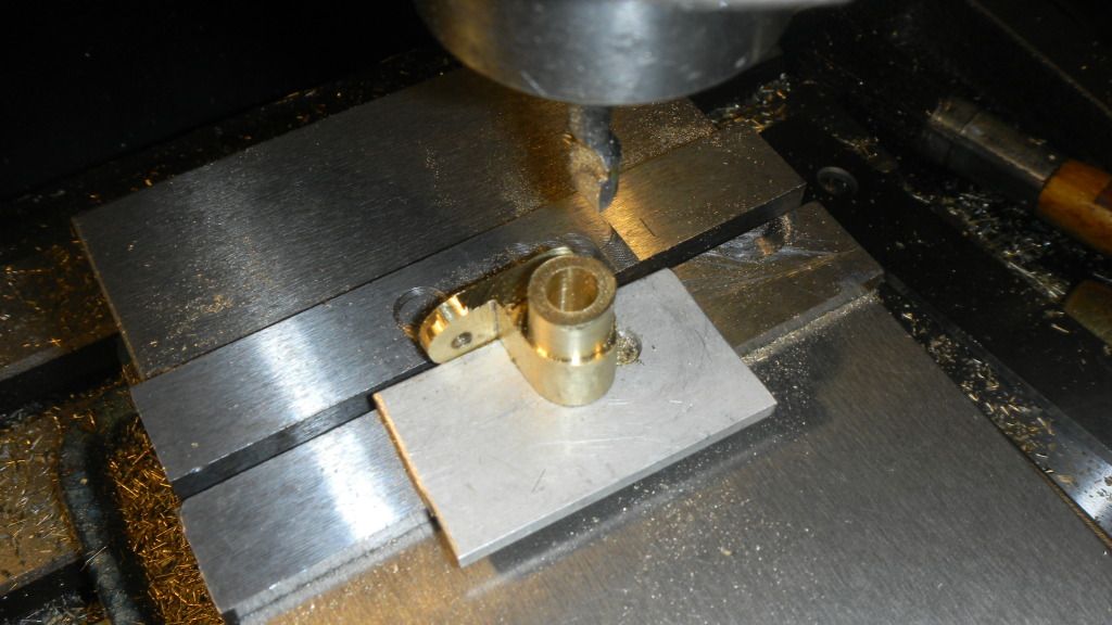
Still waiting for the material I ordered for the crankshaft, I decided to try my hand at the tapered connecting rod.

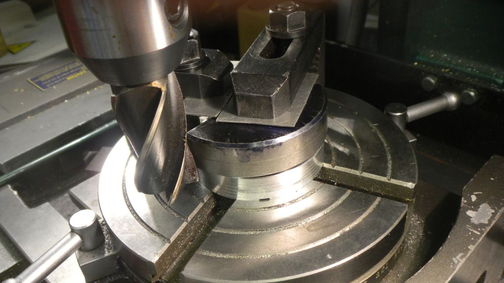
Having never done either a faceplate or offset tailpiece operation, I figured that some minor disaster was waiting in the wings.
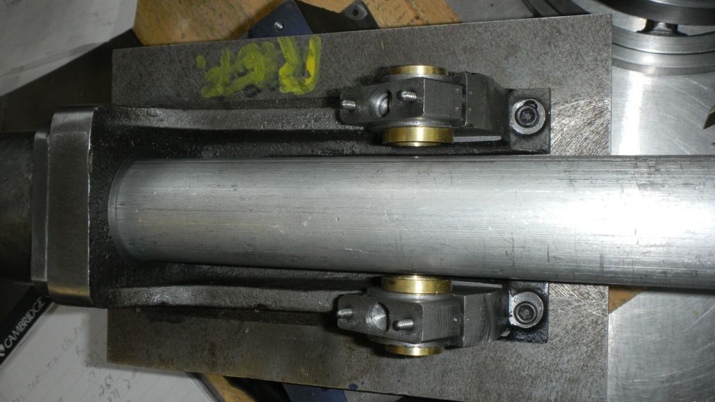
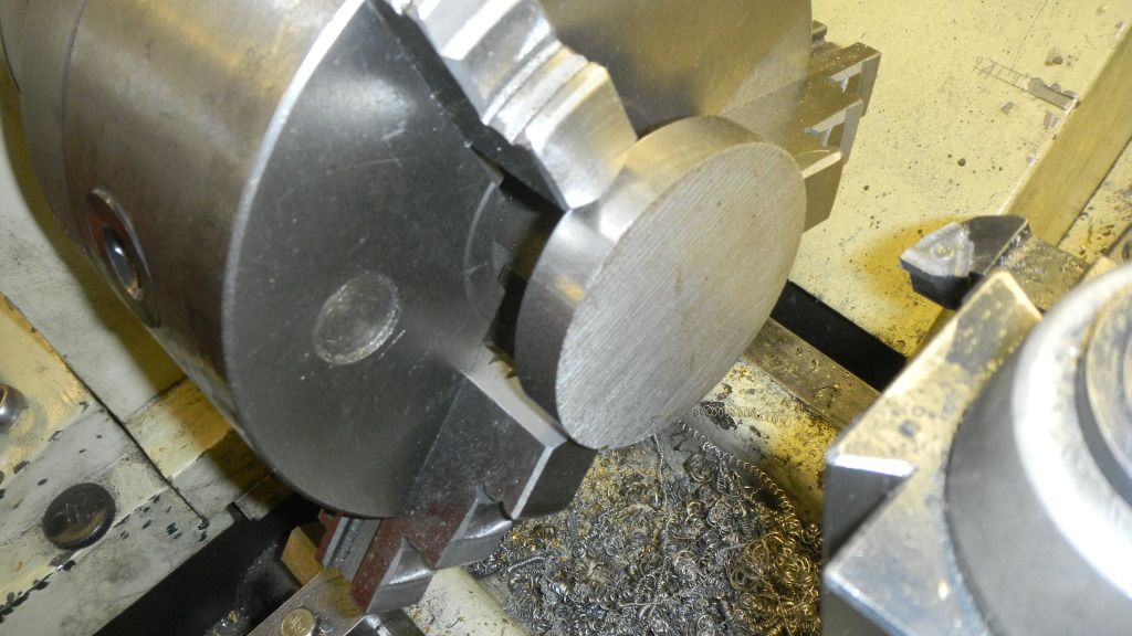
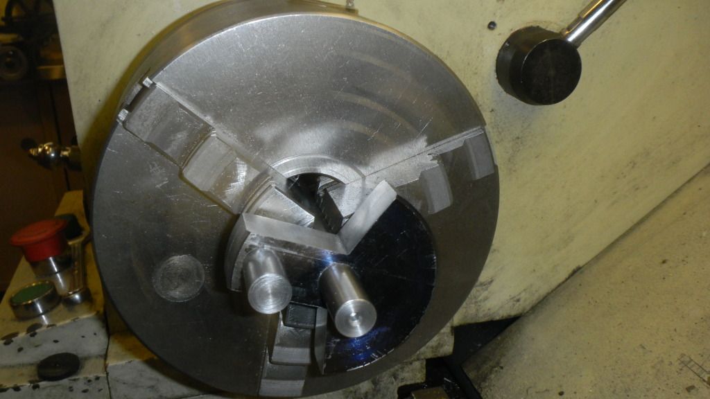
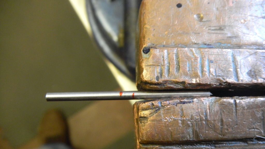
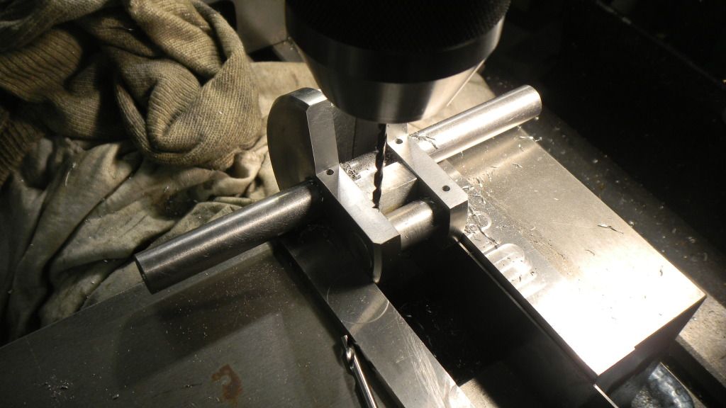
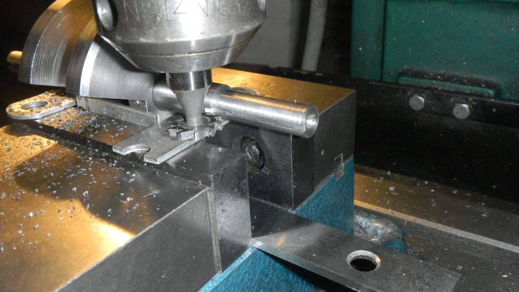
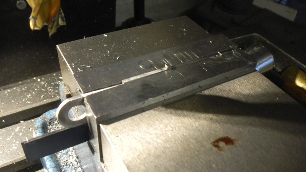
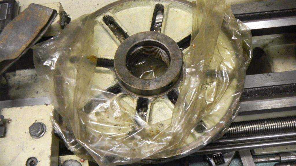
I countered bored both ends of the SS bar I had previously cut to length. Then unwrapped the never used and somewhat larger than I remembered faceplate from the plastic and Chinese cow grease protective wrap, I cleaned it up and installed it on my lathe.

DSCN1926.jpg


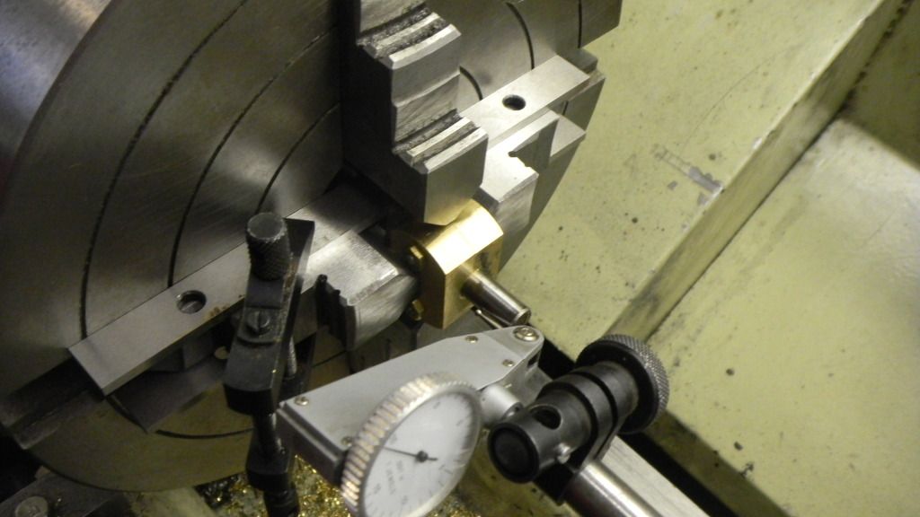
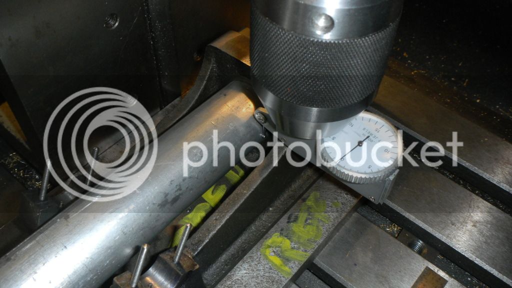
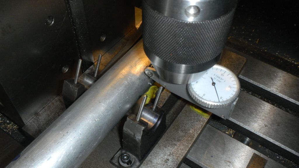
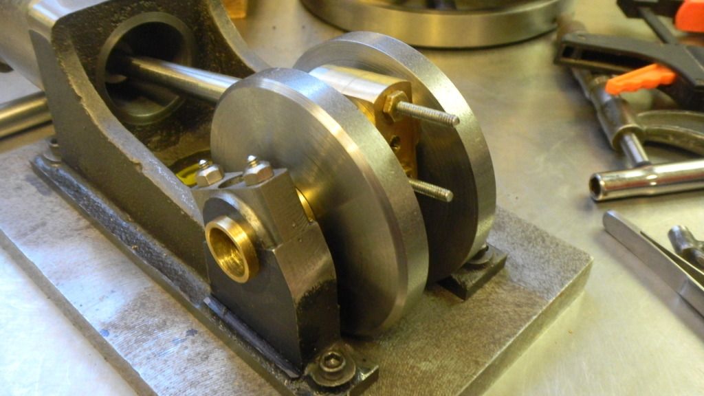
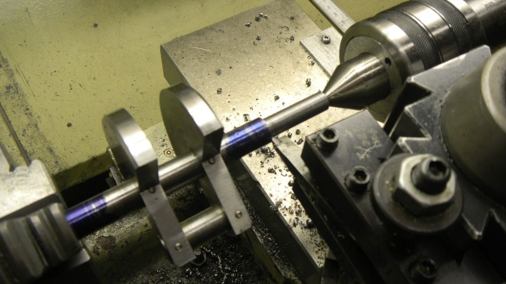
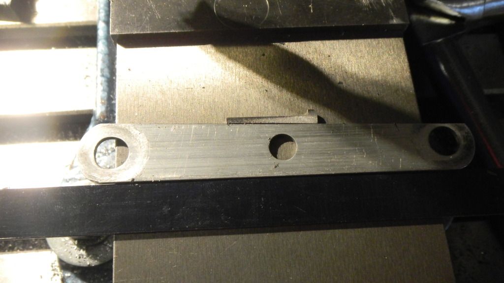
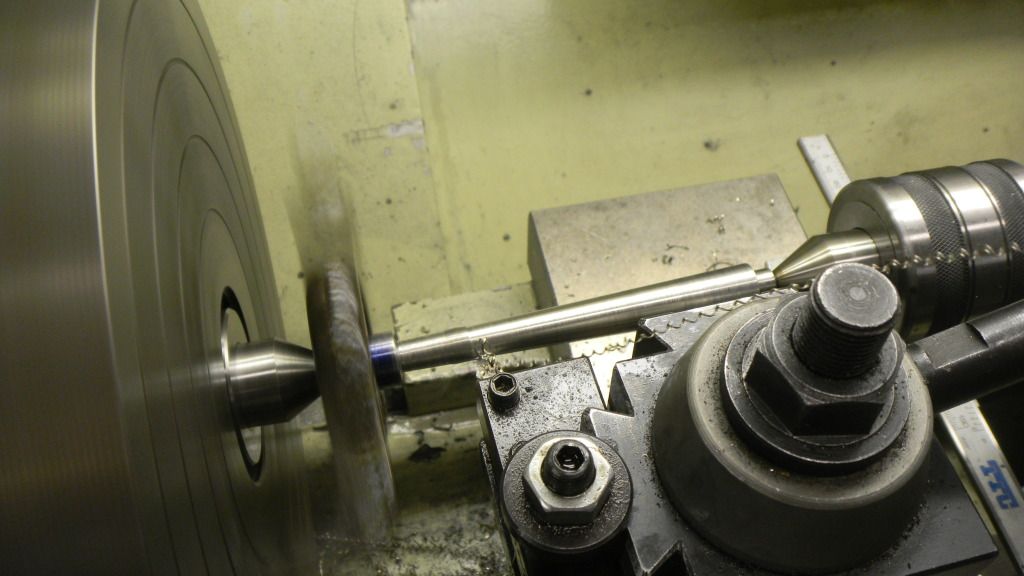
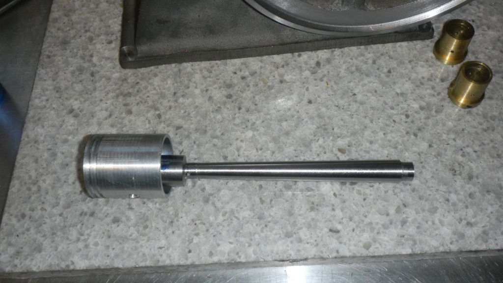
Did some complex calculations and ended up with what I thought was the proper offset for the tailpiece. About halfway into the turning I figured out I forgot to divide by 2, but the thought came in time to adjust accordingly and salvage the procedure.
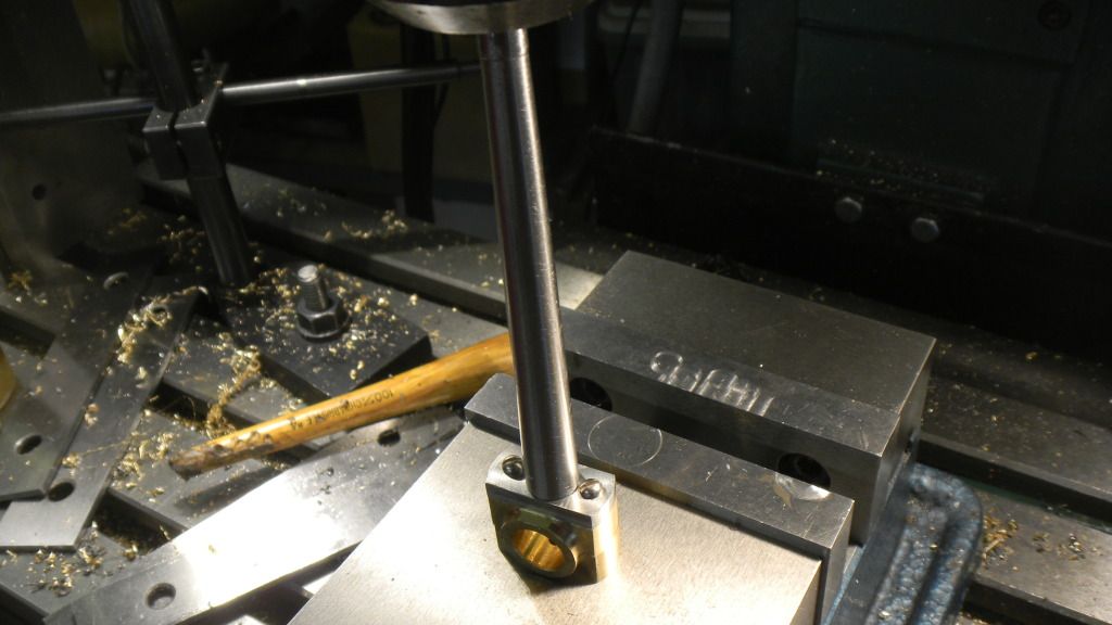
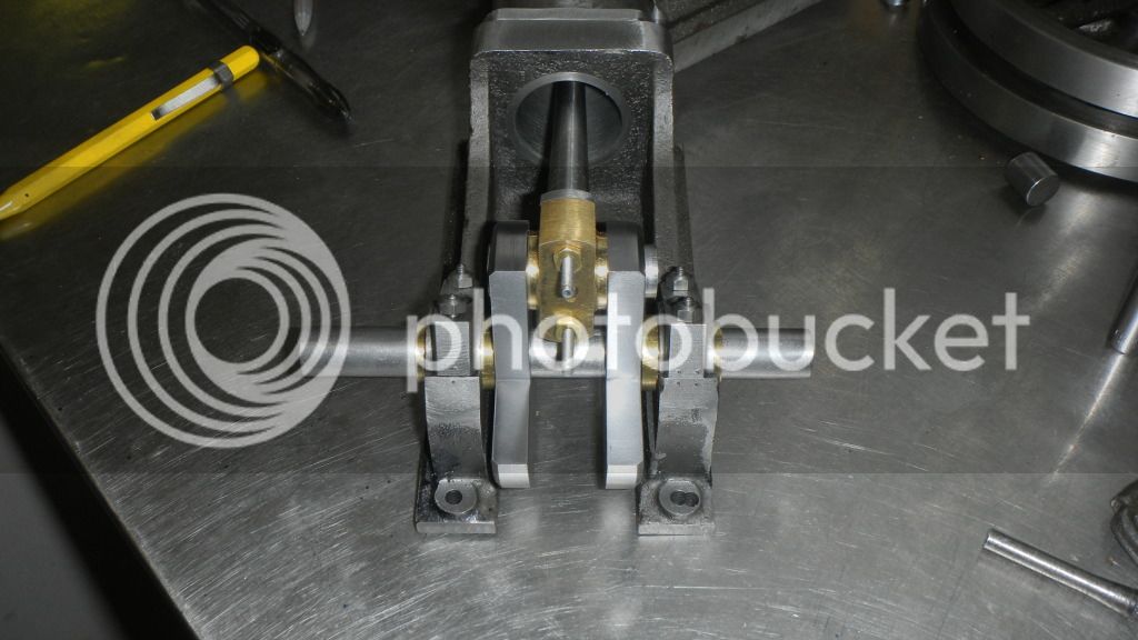
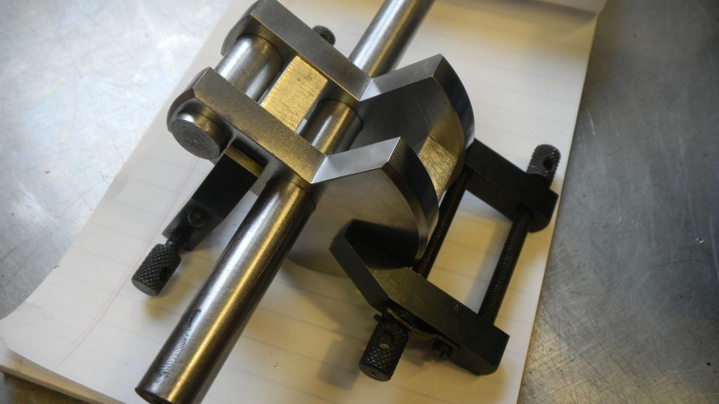
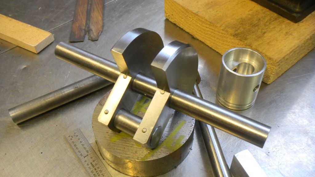
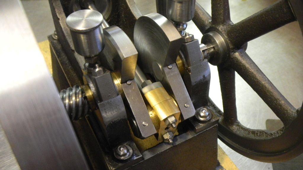
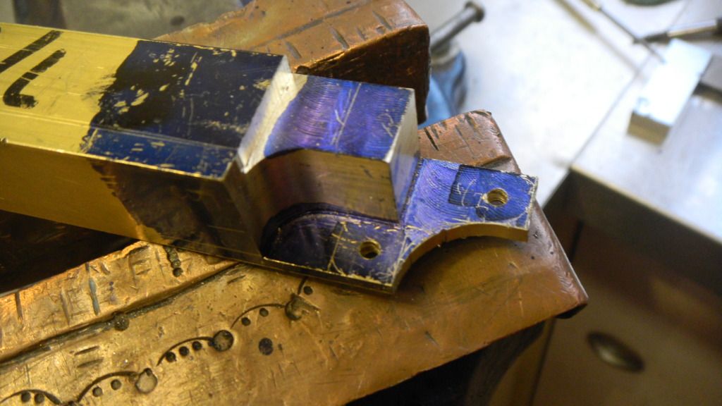
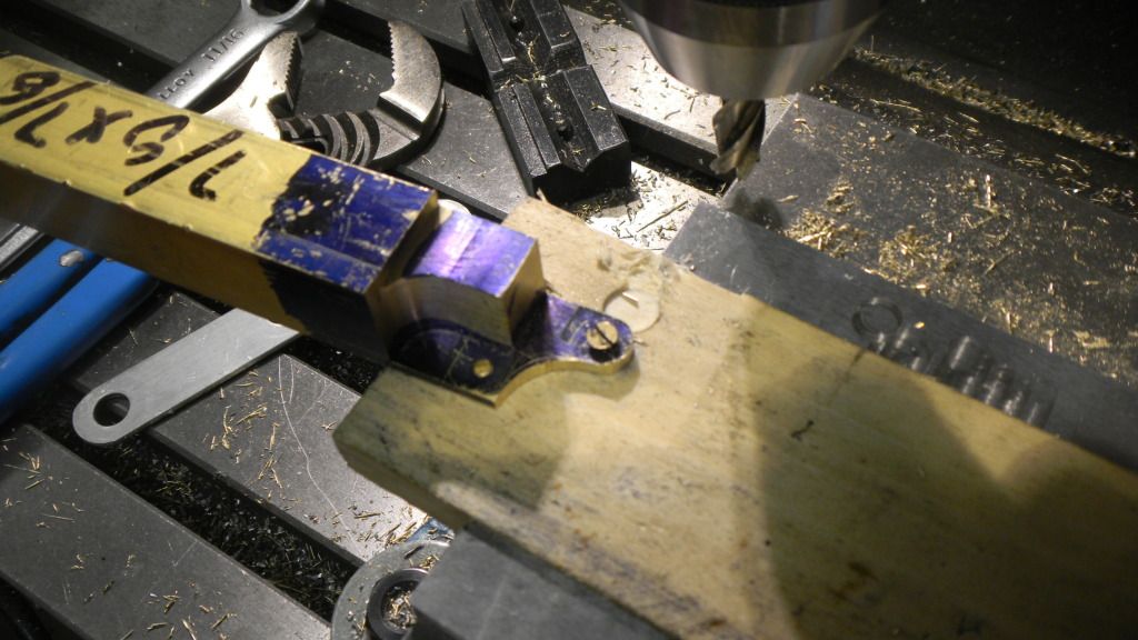
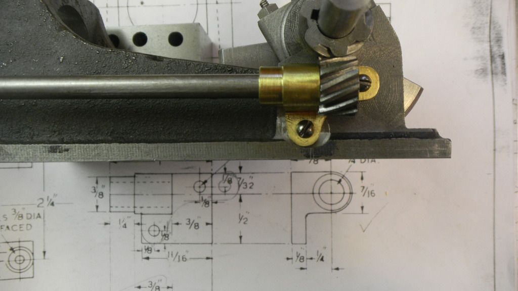
Came out looking like it should.

DSCN1928.jpg


DSCN1933.jpg
 
Then on to the big end bearing.
This should have been very simple and straight forward like the bearing caps, except for the radius.

I dug out a piece of flea market rectangular brass bar I recently acquired, put the big 4 jaw finger smasher on the lathe and dialed it in.

DSCN1945.jpg


Then to the mill and cut the flats. That done I went to the band saw to cut the shape into two pieces when I realized I should probably drill the screw holes first.

DSCN1946.jpg


Uppended in the mill, drilled the holes and finished the rest of the saw cut and faced the other piece before sawing.
Bolted together and back in the finger smasher, and I never saw this coming, when I tried to center the radiused side it would pivot instead of sliding when I adjusted the jaws. I simply could not center it and keep it the bore perpendicular.

DSCN1947.jpg


I final inserted a longer piece of drill rod, pinned it and turned the ends in the 3 jaw.
Don’t know if I explained this properly but this little sucker took a day and a half to get done.
That finally completed I made a matching SS end piece for the connecting rod, bolted together and bored for the end of the connecting rod thru the end piece and partially into the bearing. Using the drill chuck in the mill to align it , Loctitited the connecting rod into the assembly and later pinned it for backup.

DSCN1966.jpg


Getting late, making lots of typos and I have to head out early, I’ll get back to this next weekend.
GUS
 
 
Next the flywheels.
I inadvertently skipped ahead one post but that probably doesn’t mean much to anyone but me.
Since I already had the 4 jaw on the lathe, I didn’t have to risk losing a finger changing chucks.
First chuck the OD and indicate, but to what? I chose the hub, probably a mistake?
Then turned the face of the rim and also the hub. It went well, so on to the second one.
Again no problems. Life is good.

DSCN1909_zps5e39f4cb.jpg


Now to change to the 3 jaw chuck and, holding the flywheels by the hub, turn the OD , face and remaining hub.
No problem on the first flywheel, turning the OD except for this inclusion I uncovered, but I was starting to get some chatter while facing.

DSCN1911_zpsfdf8684d.jpg


I said earlier that indicating to the hub was probably a mistake and I’m still not sure.
What I noticed immediately when I started the lathe after chucking the second flywheel in the 4 jaw, was the OD had more run out than the first , but the ID of the rim (between the spokes) didn’t show nearly as much run out so I blamed the poor quality castings proceeded cutting the face and hub.
At that point I decided to do the same cut on the second flywheel and then reverse the jaws and hold the flywheels by the outside of the rim to finish the cuts. This totally eliminated the chatter and made a nice smooth cut.
I also decided that the plain face was kind of boring and crude looking, so I would make stepped rim. I flipped it around and made the step on the other side.
I saved the drilling and reaming operations for last.

DSCN1912_zpsc7dc3d65.jpg


When I chucked the second flywheel, I was confronted and confused by not only the run out on the OD, but now had considerable run out on the hub as well as the ID of the rim was now looking funny, also.

As I had to remove a considerable amount of material from the first flywheel, I decided to “Damn the torpedoes, full speed ahead“.
Putting up with the interrupted cut, I removed material until I got to the proper OD.

Then reversed the jaws and grabbed the OD and proceeded to the facing and hub turning.
While facing it started to occur to me that maybe this flywheel was not cast on center and possibly the sand flasks were not well aligned during the pour.
After I finished turning, the end result was that the ID on this side appears a bit off center and the hub is tad smaller than specified. I’ll have to keep that side facing away from the normal viewing side.
After too many years in the building trades, I learned early on that if you don’t bring attention to a minor flaw, most people won’t notice. This will be my minor flaw.
All said and done, I think they came out nice and I think the stepped rim is a nice improvement.

DSCN1914_zps8b01fd1b.jpg


I'll add that these flywheels are far from done, as they still need a lot of tuning with the Dremel and hand files.

GUS
 
Last edited:
Thanks Lee, all comments appreciated, good comments more appreciated.

Now, onward and upward, I hope.


New Problem

Something is terribly wrong!

DSCN1979_zpsce31b98c.jpg


Did I cause this?

This error became way apparent, when I first put the 1 ¼ alum. bar into the bore some weeks ago when I made the piston, and I’ve been agonizing about this ever since.
Those of you with keen eyesight may also see another dark secret of mine, the bad base mounting hole (top right), caused by my dyslexic tendencies, something that has plagued me throughout my life.
I’m going real time now, as this post is about what was/is going on in my little shop this weekend.
 
First suspect, is the cylinder parallel with the base casting?
No, it’s not. I measured .004 run out in about two inches., and yes I can shim the flat at the cylinder mount to straighten it out.
DSCN1978_zpsacfafefc.jpg


DSCN1977_zpscd06c1ac.jpg


But , what to do about the offset?

I first noticed something was wrong, way back when I was drilling the bearing mounts.
I’m not sure if it is yet another casting flaw or should I have been more careful with alignment when I was making my first cuts and drilling the mounting and dowel pin holes on the bottom of the base.
Evidently I didn’t take enough pictures when I was doing these early operations, so I have to accept the fact it is more than likely my own doing and now I have to undo something.
I simply can’t accept the crankshaft being (or looking) off center between the bearings. I have to center it and make up the difference somewhere else.
 
Although it looks like more, my considerable skills at measuring tell me there is about .090 offset between the bore and the bearing mounts. Meaning I have to make up .045”, doesn’t seem like much so maybe I can grab some space here and there, and make things “appear” to be OK.
I came up a plan where I would shave a few thou. off of the right hand main bearing and the right side of the big end bearing, maybe .010 each, leaving the rest to be picked up maybe at the crank throw thickness or the small end of the connecting rod, or possibly a new piston with an offset bearing pocket.

Not wanting to start cutting away at my now precious connecting rod assembly and risk messing things up on this half baked scheme, I decided to make a simple mock conn. rod from a piece of ½” alum bar.
I made the small end width 1/8” smaller and the made a set of shims that would simulate the offset I needed.
I also made the permanent gudgeon ( I just love that word).
Now placed in the bore with the big end side resting on what will be part of the built up crankshaft (the material for the crank finally arrived) to see what things will look like with the rod offset in the piston.

DSCN1996_zps12735a68.jpg


In my opinion, this offset isn’t as noticeable as an offset crankshaft.
And, the crankshaft will be my next project, so can dial in the offset a little better and make machining the small end the last step in this rather (in my eyes) complicated issue.

Late Note: Conn rod still seems a bit off center, maybe I will have to shave the bearings as noted earlier, or readjust the shims (make new ones).
 
Last edited:
At last, the crankshaft.

My first.

The crank on my Little Brother had already been made by my now deceased friend, so I didn’t have the pleasure (or pain) of having to make one for the first time.
In all of the time I’ve been cruising this site, the crankshaft has been a somewhat mysterious and difficult looking process.
One piece or built up.

I don’t want to consider a one piece, in this instance, simply because of the large crank throws. At 2 ¾” dia., I would be trying to turn a 5 pound piece of steel into a half pound crankshaft, not only a lot of chips but a lot of wasted time, in my humble opinion. Besides the built up crank looks a lot easier although I’ve seen some posts much to the contrary. BUT, I’m all over easier as much as I love making chips.
Sooo, I will make this 2 ¾” piece of cold rolled into 2 crank throws. I know there a lot simpler ways to make a crankshaft, but I love the look of these with the built in counterbalances.

DSCN1998_zps22e6fc4d.jpg


First, slab off a couple pieces of the bar in my aging Marvel Drawcut hacksaw, allowing for the finish cuts.


DSCN2001_zpsd3600dbd.jpg


Then to the 3 jaw to cut the proper thickness.

DSCN2004_zps6b5ff321.jpg


That done, a quick mock up and things look good so far.

DSCN2009_zpsb5467250.jpg
 
This is why full size drawings are nice. Instead of messing around trying to lay this out , armed with an angle gauge and various other measuring tools, I took the easy street method and simply extended the cutout lines on the full scale drawing, I layed the Dychemed discs on the drawing and scribed the cutouts.

DSCN2012_zps4407d94a.jpg


I know my lines look off, but that is mostly the effect of the lense being in the upper left corner of my fixed focus Nikon. A simple camera that fits well into my lifestyle.
Now to the bandsaw to make some more scrap iron.

And here are the cut out pieces waiting to be Lactated (lightly) together for cleaning up and boring holes.
That’s supposed to say Loctited,, must be some sort of fixation an my part. :rolleyes:

DSCN2019_zps3a79ea29.jpg


That will have to wait for next weekend.
Although today’s efforts have been writing, posting, thinking, machining and more writing and posting, I have to take some time to sit in the sun with Louie (my beloved Jack Russel), on my lap, have a couple of beers and enjoy what has developed into a stellar early fall day.
It don’t get much better than this.:D
More next weekend, I hope.

GUS
 
Hi Gus

Darn castings anyways; they are always a compromise one way or the other. The thing about flywheels is to try to get the un-machined surfaces running as true as possible; but they will never be dead on. The inner rim where the spokes meet the rim is the most noticeable when the engine is running.

You are making great progress and I sure you will also get the cylinder/crank alignment sorted out and on to next piece on the pie.

Dave
 
Following with interest Gus. Especially this built-up crankshaft.

Regards,
Rudy
 
Dave, Yeah, I have a lot to learn about working with castings plus about a million other things related to machine work, sometimes boggles my already boggled mine.
You especially wouldn't want a peak, we would make a good "odd couple", my mind is as cluttered as my shop.
Been following your Pacific build, totally impressive, kind of scares the hell outta me, got a lot to learn.

Rudy, If screw ups are interesting to you, just keep watching.

New Post:

I was going to post this over morning coffee, but I thought it necessary to go out to the shop and grab my camera to check out what usable pics I had taken., But there were none really worth seeing, but, because this was what going on in my head this morning I am going to post it now a little before dinner.
 
The cut out crank discs now glued together, got cleaned up, drilled and
reamed .001 under ½” and the holes are a nice snug fit with the ½” cold rolled shafts.
Looking pretty good, I stood and admired my work for a bit, and still glued up I decided to give it spin in the lathe.

DSCN2028.jpg


PLAN AHEAD, make decisions as to the machining sequences BEFORE you start cutting (I keep telling myself).
For some reason I just couldn’t wait to make those saw cuts on the flywheel discs and it just came back and bit me on the a….
I should have drilled the crankpin and crankshaft holes first. The thought hit me like a brick :wall:as soon as I put the glued discs in my mill vice to clean up the sawcuts, I think it was a cinder block :fan:that gave me the next lump when I finally got around to drilling the holes.

I was figuring the cuts would only have to be somewhat approximate and I now had no accurate way to measure the centerline and if I had drilled first (or even laid a center line) I could have used the holes with short pins in them to accurately make the clean up cuts. I knew I was in trouble but continued.
End result is the OD of the crank is noticeably off center when spinning. I just know the machinery police are going to bust in any time now and cut the power in the shop and lock panel box.:hDe:
If nothing else, I think I should get a booya for good use of emoticons.


NEW PLAN.

Clamp the still glued crank throws to my rotary table, centered on the crank hole, and mill the crank back to round. I thought of trying this on the lathe but I don’t want to feel the wrath of the brick again and so soon.
This will be today’s work after I change the oil on Mama’s car.
Wish me luck (with both).

GUS
 
Last edited:
Just discovered this thread. If you find you need to remake the crank webs, there was a letter in Model Engineer which claimed that as designed, the engine is under balanced, and was improved by increasing the counterweight diameter to 1.6". This could be done by attaching extra weights, and your reciprocating weight is going to be a bit less than standard with an ally piston.
 
Ian, That kind of makes me not feel real great, considering I just deacreased the OD by about a sixteenth. Maybe by substituting alum. for the specified C. I. will lighten the load.

New Post

Good news, oil change cancelled, bad weather.
More good news, my new plan worked.
Took a while to get the rotary table setup, clamping seemed to be the big problem, but after that things went great.

DSCN2030.jpg


All said, the crank throws are now a scant sixteenth under proper dia., but they spin nice in the lathe, although, I can’t spin the crank in the engine yet.

DSCN2038.jpg


It’s hard to tell, but the crank is offset .028 to the left and the big end bearing another .018, total .046, half of the error. The rest of the offset will be made up at the little end. On this pic it looks like it's already offset too far, but that's just the camera angle, I think.

DSCN2040.jpg


All in all, I feel way better than I did this morning,.
It seems correcting errors (salvaging things )is way more fun than getting in trouble.
I’ll end my workshop day here, on a positive note.

Tomorrow, I think I’ll figure out the rest of the offset problem and get the little end of the connecting rod done before I get up the courage to go on with the big glue up.:p
Everything seems to be on course, but sometimes the Loctite 609 grabs before you get things where you need them. Something like trying to set a piece of laminate on contact adhesive.


Stay tuned for more adventures.
GUS (the other gus, generatorgus)

PS Gus, I've been reading your post with interest.
 
Last edited:
I’ve been away from the shop for a bit. My work assignment has gotten somewhat ugly and my weekend interrupted by a wedding in Maine.

Not complaining about the wedding, had a wonderful time, but the 9 hour drive each way was exhausting and it took up a day each way. Weekend progress on the Wyvern pretty well shot.

But, because I’m “semi retired” and because I can, I decided to blow work off this week, let someone else try to unravel the mess at the jobsite (not my doing anyway) and try to salvage my sanity, if that’s even somewhat possible.

As things normally go for me, I’ve had a change of plans. After measuring, as carefully as I can, I’ve decided to leave the small end of the connecting rod for after I get the crankshaft in order. After shimming the cylinder to parallel, the offset problem has dwindled to less than I thought.
So on to the crankshaft and into the dark for me. I’ve done considerable reading on the built up crankshaft subject, about 50/50 pro and con, but built up is where I’m going.
I’ve managed a fairly snug fit for the crank pin and crankshaft to the throws and, in my mind, proper alignment will be achieved if I keep the crank throws clamped parallel when every thing is assembled.

I made a parallel shim from a piece of aluminum, a couple thousandths wider than the big end bearing.
This is the set up.

DSCN2044.jpg


The crankshaft kept full length, is the first to be glued. The crankpin was kept in for alignment, but not glued yet. The marks on this end of the crankshaft are black marker to indicate the end that I could handle so as not to contaminate things.
After the Loctite has set up, the crankpin, cut a tad longer than to OA width of the crank throws, was next.

After that was set, I made up some pins from some .093 shafts, gleaned from an old copy machine.

DSCN2046.jpg


With the clamps now removed, drilled appropriate diameter holes, again snug.

DSCN2048.jpg


Then, Loctited and “pushed” the pins into place.

DSCN2053.jpg


Now, I’m keeping my fingers crossed that everything is OK.

Note, the crankpin and pins are left deliberately long as will be the crankshaft when I get around to cutting the portion between the throws.
While doing the fit ups I decided this look would be appropriate for a built up crank and to is much to my liking, as well as being much easier than trying to blend them in.
The center portion of the crank will not be cut until I turn the ends to accommodate the 3/8” dia. of the flywheel and skew gear holes. I still have to do some thinking on how to secure the flywheels.

Drawings call for a 10 degree tapered split bushing and 3/8” nut to hold them in place, not sure I’m ready to attempt that. Looks a bit problematic to me. In most of the pictures of this engine I can find, the nut is always hanging out past the shaft.
I’m thinking tapered gib key, but am open to suggestions.
I’ll be going to Coolspring next week and will poke around in the museum buildings looking for ideas on this and some other thoughts I have.

Not sure what today will bring, last night (3 AM) I had to make a service call to a restaurant I do maintenancence for, got home at 5:30, the loss of sleep hasn’t hit me yet.
I’m sure I’ll end up in the shop, but I also have to start getting things ready for Coolspring, trailer, camper, etc.
We always get there on Tues. and stay until Sat. Makes a nice little vacation.

GUS
 
Last edited:
Hi Gus

I envy you being able to spend most of a week at the antique engine Mecca.

The crankshaft is coming along nicely; I thought for a moment that maybe you were going to silver solder it together.

Dave
 
Dave, I can handle silver solder quite well. What I can't (don't want to)handle is the clean up. Seems a shame that you have to mess up something that took a whike to get looking nice.
I know there are ways to make clean up easier but the Locitite cleans up with a paper towel. I'm sure I'll see what happens.

I gave it a try, I like to experiment a bit, I hope it doesn't bite me on my A>>>. :eek: If it comes apart, I can always start over, it wouldn't be the first time I had a do-over besides I need the experience.

Coolspring is a must do, lots to look at in the museum buildings as well as the show grounds. Lots of folks from across the country as well as overseas.
I once sold a genset to a guy who had to take it home on an airplane, we had to take it apart to get it in his rental car.
It's difficult to go there and not come home with some sort of trophy, as well as a smile and the feeling that you want to go back.

GUS
 
Although I still haven’t decided how I’ll secure the flywheels, I decided there was no reason I couldn’t at least reduce the crankshaft end diameters to fit them.
Deciding the length I needed to reduce the cam shaft side was the big question
as I don’t have the skew gears on hand yet, and they will be different than the drawings spec.
I decided that stopping just short of the main bearing had to be the answer, because regardless of the different size, any deviation can be corrected on the width and mounting height of the cam brackets in order to get the centerlines right.
One end in the 3 jaw and the other backed up by a live center in the tailstock, the flywheels now have a nesting place.

DSCN2058-1.jpg


That done I moved right onto the connecting rod and the troublesome offset between the cylinder and main bearings.
I already made up some of the difference in the main and big end bearing and now the remainder will be taken up by the small end at the piston.
I came up with this setup and simply worked from the center of the small end dia. Using the measurements I came up with for the offset, cut the flats and then drilled and reamed the wrist pin hole.
No, that’s not rust on the 2,4,6 block. It’s left over bear grease that never got cleaned out when I got them.

DSCN2063.jpg


I must have done something right as, when assembled, the piston moves nicely in the bore with no resistance, at least for the 2/3 revolution I can get from the crankshaft. And the crankshaft is running true.
I’m not going to cut out that center section until I’m sure where I’m going with the flywheels.

Hello~~~ Backup a bit. As I’m typing this I suddenly realized I forgot the small end brass bushing.
embarrassed.gif
Hoo Boy, that’s what I have to put up with, I get focused on something and blow right by an important step.
The engine would probably run a long time before it became an issue, but, the bushing will be included in today’s to do list.

Chore taken care of, the gudgeon now has a softer pillow.
While on a roll, I parted off a couple of 1/32” thick pads for the wrist pin ends from a piece of 3/8” brass round. Sorry to say I have no ¼ round so I had to waste some material.
The connecting rod/piston assembly is now complete.

DSCN2070-1.jpg
Somehow, this picture uploaded vertical
Also accomplished are the oil holes in the small end and piston.
And, for the days parting shot, I glued the cylinder into the jacket and will drill and tap the oil cup hole tomorrow after I’m sure the Loctite is done adhering to anything it gets near.
In the past two days I managed to stick a bearing cap to one of the main bearings and one of the crank throw spacers to the crank throw.. Not big time stuck, but I have to be more careful. A little WD or grease would go a long way to minimize this problem. It’s a wonder I haven’t stuck my eyelids together yet or maybe worst.
All said it was well worth taking the week off. I’ve relaxed some and also got some of life’s other chores done.

Also, today became apparent to me that I’m rolling along with this project and now I have to try to plan out the front end of the Wyvern. The cylinder head and carby ought to be real hoot. So far, I haven’t deviated too far from the plans, it will be interesting, to me, to see how this plays out.
Tomorrow I will temporarily assemble all of what is complete and take the engine to Coolspring, next week, and display it as “A work in progress” (go figure).
It’s really nice when someone stops and gets really into the stuff you’ve been spending a lot of time and effort on. Kind of spurs you on.

GUS
 
The trip to Coolspring, now a pleasant memory, was just great. The weather held and we had 3 very nice sunny days, and a bit of rain, mostly at night.
I spent a good deal of time jawboning at my set up and had to pull myself away to go see what else was going on, and there was lots.
This is one of those Coolspring moments, Thursday night after the rain, Louie’s feet were wet, my wife wrapped him in a towel and sat him in his stroller in front of the fire.
He sat there, warm and content, quite some time.
Also in the picture, my wife (right), and my pal’s girl friend (left).

DSCN2098.jpg

 
We got home Sat afternoon, unpacked and the I headed out to the Jacktown (Blue Mountain) show Sunday. More nice fall weather and again, lots going on.
While there, I met up with Bob Herder and picked up the skew gears for the Wyvern.
With show season at end and spur gears on hand, I can now continue to make some progress with my project.
While at Coolspring, I decided that tapered keys would be my answer as to how I would attach the flywheels.
I cut the keyways in the crankshaft with a woodruff key cutter.

DSCN2105.jpg


After that was accomplished I decided it was time to broach the keyways in the flywheels and drive skew gear. While getting ready to do so I noticed that, when viewed from the end, the keyway on the crankshaft looked a tad off center. I went back to the mill and found that I somehow used a 1/16” keyway cutter instead of the 3/32” cutter I intended to use for the crankshaft. :Doh:


Back in the mill and this time with the proper cutter I recut the keyways.
Then got on with the broaching, a pretty simple operation and things went well.

DSCN2103.jpg
 
Now to make a couple of keys gib keys.
The last gib keys I made were done using a hacksaw and file, although I wanted to make them in the mill, I couldn’t come up with a simple way to do it.
This time I’m using the mill.
I used a piece of 3/16” key stock and milled it to the 3/32” thickness I needed, then checked the fit.

(Yes, the flywheels still need to be cleaned up, it will be tedious work and I'm avoiding it.)

DSCN2115.jpg


That was the easy part. At this point it would probably have been just as easy to get a file and finish the job, but I wanted to do it in the mill, and trying to hold the small piece and accurately set the angle became the only hurdle.
I have angle blocks but they are ¼” thick, so I needed to make a thin angle block a tad thinner than the key.
Easiest thing I could think of was to stack four pieces of scrap alum, and mill the angle on all four. The angle block is sanwiched between the paralells and the alum. scrap.

DSCN2112.jpg


Then using one to set the angle on the key. Stacked in the vice are a couple of thin parallels, the thin angle block and the key.

DSCN2128-1.jpg


It was still trial and error to get the thickness right, but it worked.

DSCN2129.jpg


I’m thinking that the angle could be another degree or so (I chose 2 degrees), but the keys fit good and I’m moving on.
 
Last edited:
With all this accomplished it was finally time to remove the middle section of the crankshaft from between the throws. Band sawed rough and the cleaned up with an end mill, the crankshaft is now finished.
Reassembled, the crank can now perform it‘s function. Mission accomplished.

DSCN2123.jpg


With the crank now finished I can get to figuring out what modifications I have to make to the inner sideshaft bracket to make the skew gears work, being that they are a bit different from what was specified.
Right off the bat I noticed there would be a fastener problem as one of the screws would be directly behind the driven gear. I could use a flathead screw, but why not just extend the bracket and fancy it up a bit.
Looking at a number of pictures the Wyvern engines I found, it seems that the cam bracket has been modified, suggesting that the bracket, as drawn, has been a problem child.
My version works, by if I had researched a bit before hand, I may have done it differently.
After mapping out my strategy, I searched my metal stock and selected a piece of 7/8” square mystery brass bar, gleaned from a flea market.
Having learned at least something from passed experience, I actually took the time to lay it out on the work piece before I started cutting.
Then bandsawed some of the waste, went to the mill and started work.

DSCN2133.jpg


After more carving I began to more fully appreciate the word casting.

DSCN2135.jpg
 
As work proceeded, I decided to make some more layout marks to help avoid making an error, then went back to the mill and did some profiling and drilled the mounting holes.
It was now starting to look something like I wanted.

DSCN2139.jpg


Now to round out the areas around the mounting holes.
Having had some problems in the past using machine screws for a pivot, either unscrewing or tightening up enough to make it difficult to turn the work, I decided to try a flat head wood screw in a piece of wood.

DSCN2140.jpg


It worked pretty good on the first hole so I proceeded and had no problem with the remaining hole.
After rounding out the top, the piece was turned on end, the hole for the shaft drilled and reamed, then the outer diameter cut with the boring tool.

DSCN2145.jpg


I put the shaft with the gear in the bracket and again performed a progress check.
I got a small surprise. I assumed the flat on the engine base would plenty big enough to accommodate the bracket and it wasn’t. Now I could either scrap the piece and go back to the drawing board or… just notch the base wee bit.

DSCN2171.jpg


But wait
One more teensee little problem.
(to be continued)
 

Latest posts

Back
Top