Brian builds Atkinson Engine

Home Model Engine Machinist Forum

Help Support Home Model Engine Machinist Forum:

This site may earn a commission from merchant affiliate links, including eBay, Amazon, and others.
That head is really nice. I didn't realize how big this model is. Should make some nice noise when it's running. ;)

Todd
 
Well sir!!! I just set down to take a close look at what I have to make yet, and there isn't very much left. I ordered the timing belt and two pulleys yesterday. I made the "muffler" this morning.It seems that all I have left are two cams (one for each valve), a plate to mount the ignition points on, and having saved the best for last, two valves and valve cages. This is my third I.C. engine. I first built the Webster, and through beginners luck had very little problem with the valves sealing properly. Then I built the Kerzel hit and miss, and went through absolute Hell trying to get the valves to seal and give enough compression for it to fire!!! Both of those engines had a "vacuum" operated intake valve with very light valve springs, so the seal between valve and seat had to be perfect, because there was very little spring pressure to hold the valve into the seat. This engine has a mechanical lifter for each valve, so I should be able to use heavier springs---which SHOULD mean that it will be easier to get a good seal on the valves. I also have to build a ball check valve to go into the fuel inlet line, because in theory a backfire when trying to start an engine with a "vapour carburetor" could shoot a tongue of flame back thru the line into the gasoline tank, resulting in a nasty explosion. I have never actually heard of that happening, but I don't want to be known as the one person in a thousand that blew himself up while trying to start a model engine. This picture also shows the additional material which I added to the outer diameter of my brass flywheel to bring it up to the full 6" called for in Jan Ridders plans.
ENGINEWITHMUFFLER-2001.jpg
.
 
Looks really good Brian coming along nicely part by part, I hate waiting for shipping LoL

tom
 
We know you can do it Brian. Just think Valve Cage, Seal. Valve Cage, Seal. Valve Cage, Seal.

Ray
 
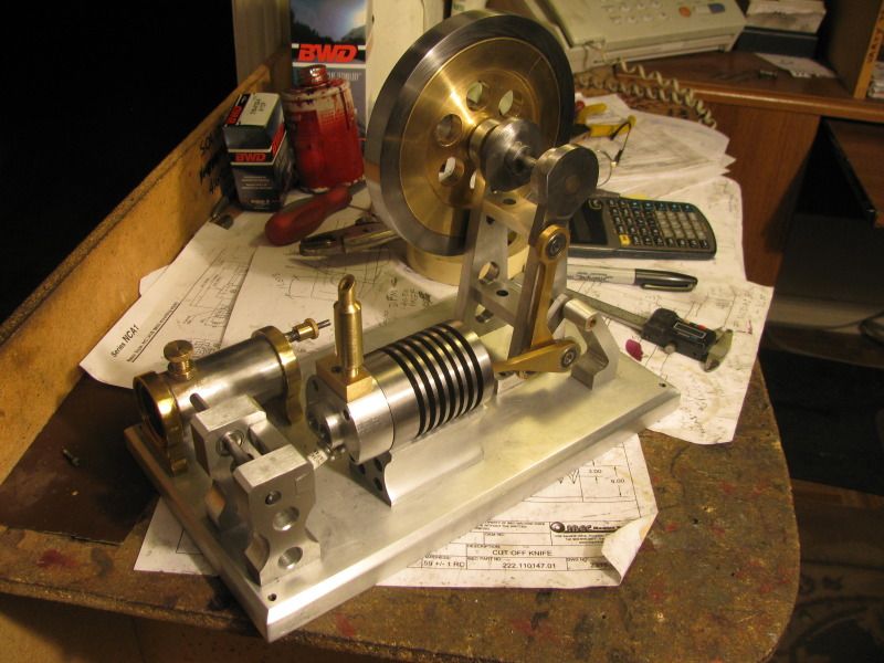
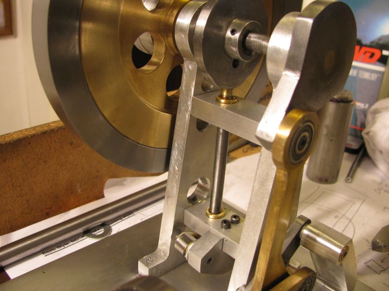
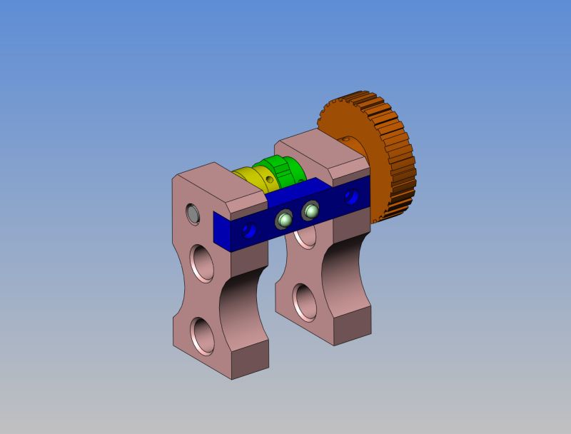
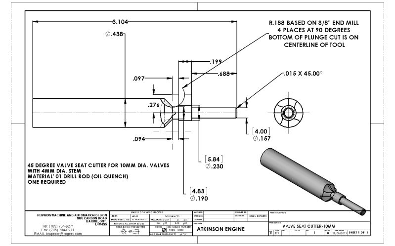
Aaahh, I wish I could share your confidence that the stronger springs will assure a good valve seal. On my 2 cylinder open column engine, I had cam actuated intake and exhaust valves with stronger springs, and still had a devil of time getting the valves to seat. Seems to be hit and miss with me (no pun intended), but my two engines with atmospheric intake valves worked flawlessly pretty much out of the gate, the one with cam operated intake valves gave me fits.

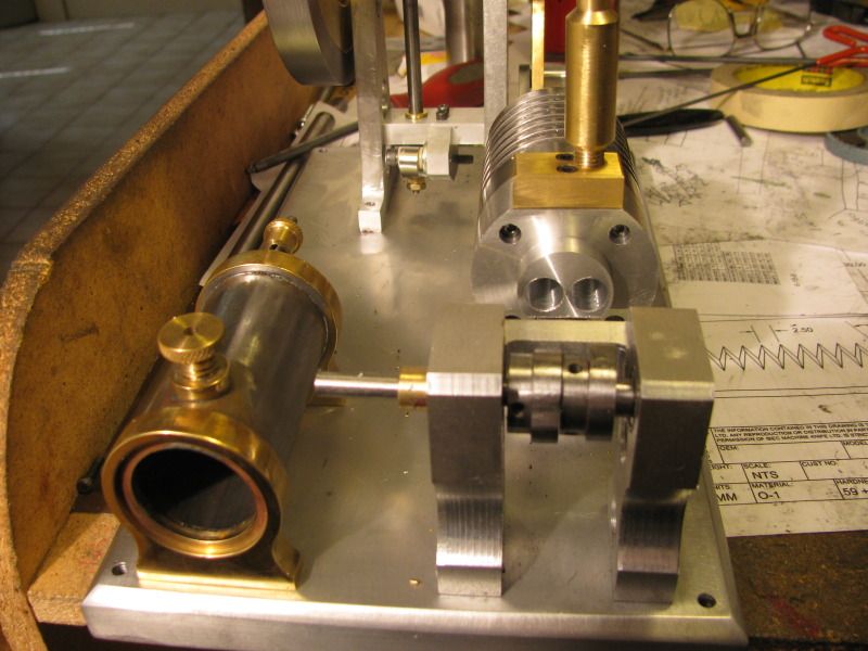
But, on the other hand, maybe your previous experience will make this latest engine less troublesome! Lovely engine and beautiful craftsmanship, nonetheless.

Chuck
 
WE HAVE IGNITION!!! ---Well, at least we have ignition points, and the mmechanism to drive them. On the original cam, as designed by Jan, there was a 0.100 rise on that cam, which pushed a rod down to beat a spark out of a piezo electric crystal. I have opted to use a set of Chrysler automobile ignition points as mentioned earlier, so I shaved that cam down in my lathe today to give about 0.040" rise. Since the cam itself is steel, I mated a brass end onto a peice of 1/4" cold rolled steel rod to act as a rubbing block, and the other end of the rod bears against the nylon rubbing block on the ignition points. The cam is attached to the shaft with 3 setscrews at 120 degrees, so that lets me play with the ignition timing. It all works quite nicely, really.
WEHAVEIGNITION001.jpg
 
Neat modification. Do you know what you will use for a coil?
 
This morning I got up and started on the two cams which operate the valves. There are multiple operations to be performed on these, so I thought that since the first operation was all straight lathe work, I would start from both ends of a peice of 1020 cold rolled that I had. I woke up at 6:00 full of "old man pains" which I'm sure a lot of you can relate to. Finally at 7:00 I forced myself out of bed and came down to the shop, closing about 5 doors behind me.---Still managed to catch Hell from good wife when I was finished at 8:30 for having woken her up at 7:00!!! Anyhow----Jans method of making cams is different than I have seen done before. He turns 2 or 3 full diameters, drills and reams while still in the lathe, then parts off the material and uses a rotary table to cut away the profile of the cam from the largest "disc" formed in the preceding lathe operation. I'm not sure how well this works, but it does away with offset centers and 4 jaw chuck work. You will notice that each turned part has a long tail left on it. That is to hold in the 3 jaw chuck mounted on my rotary table. Then after the cam profile has been cut that long tail is mounted back in the lathe and the cam is parted off. I rather like this method, although it wastes a bit of material. All of my turning on these parts was done with brazed carbide, so the finish is not great. Of course by the time I do the rotary table work and cut the tails off, there will be very little of the original machining left to see.---and emery cloth is my friend!!!
cams-2002.jpg

cams002.jpg
 
Hello Brians, Hello All,
Very nice work that you accomplished on this Engine, I admire you for your sense of made well work, you are job what would explain your skill in the machining!

Is it true that by giving via PayPal at Mister Jan Ridders, is it possible to acquire several plans of ours choice in one only one time, I do not know any more in what post I read it on the forum.
if it does not disturb you to answer me, you have a job in this domain to control as well all your work, or it is just your passion just as us all here to construct, (it would surprise me that it is just a simple passion, but I would not like to be indiscreet, excuse me), I know that is made on Conventional Machines, but to see them it would be possible to think that everything in summer made in Machines CNC, and however NOT... Is-it not Fabulous...

I have yet ever fabricated Internal combustion engine as those of the Mister Jan Ridders, however I would really like to try to make one, knowing that I is always made only recommend me you as first so as to financial year of beginner in the field. I have the Whole collection of STRICTLY I.C. .(I do not launch haphazardly in a Machine of which I am not on to be able to finish, they seem to me too much Complicated, I should rather have sold, the Magazines of the Collection Modeltec, if it was to do again without the slightest hesitancy !!!
While the plans of Mister Jan Ridders seem more accessible to the beginner of Engine I.C. constructor that I am !

Still bravo to you for the splendid Work which you did since the beginning on this engine.
I know that it was accomplished on Machines conventional to be looked really there, all photos are there, you have a lot of know-how it is what there is it more precious and to each of us.
It is what makes this Brilliant Forum: the diversity of knowledge of each of us encourages us to move forward when the Work of some and others is looked I find it very rewarding!
It is of what I think and especially it is only my personal opinion.
See you soon, Cordially
Jean-Michel.​
 
Luky Luke---Thank you for the nice message. I contacted Jan Ridders, and for some reason he does not sell his plans. He will give you his plan and ask for a donation of about 10 to 15 Euros. I am sure there must be some legal reason for this. My "real" work is a "Design Engineer" in which I design automation and prototype machinery for industry on the computer www.rupnowdesign.com but I do not build the machines, I only design them. For most of my life, hot rods and drag reacing has been my passion, and I am still involved with that to a limited extent. . However, I am older now (66) and I find that building racecars is just too much work. I bought a lathe and a mill 5 years ago, and began making small engines, both steam and petrol powered. ----Brian Rupnow
 
This is a shot of the exhaust cam after the profile has been 95% cut in the rotary table, as well as what it looks like cleaned up a bit and removed from the chuck. All that remains now is a bit of filing at the corners of the cutter run out, and parting off to correct length.--And yes, those are chatter marks on the side from a previous operation, and yes, when I locked the part in the chuck I had a small flat washer on top of each chuck jaw so my milling cutter wouldn't cut into my chuck jaws. The washers were removed before any milling actually started.
exhaustcamcut002.jpg

exhaustcam-2001.jpg

exhaustcam-2002.jpg
 
And here we have it!!! Two beautifull valve cams, finished and installed. Now all I need is the belts and pulleys I have on order to turn the camshaft. You can see in the 3D solid model which views the cam tower from the opposite side the two very short pushrods which ride in guides between the cams and the ends of the valve stems.
CAMSINSTALLED001.jpg

SUBASSEMBLYOFCAMSHAFTSTAND.jpg
 
Wow! You're moving right a long Brian. This really is a fascinating build to follow. Thanks for sharing. :)

Todd
 
Wonderful progress. I like your approach to machining cams.
Ernie J
 
Brian, I see you're still up to your usual high standards in documenting and machining. Very nice looking engine.

-Trout
 
This is the valve seat cutter I will build and use to ensure concentricity between the hole for the valve stem and the valve seat in the valve cage.
VALVESEATCUTTER-10MM-rev-1.jpg
 
We're getting right close to the down and dirty now!! These valve cages are turned to size (a slip fit into the 10mm bores in the cylinder head). They are drilled and reamed 4mm diameter thru the full length, and then a 1/4" counterbore drilled in the end closest to the valve. Now normally, the valve seat would have been turned while in the initial set up----One would expect that by doing that, the valve seat would be perfectly concentric with the 4mm reamed hole. However, I KNOW that that is not necessarily so--those damned small drills wander off center, and the reamer follows them. The 4 mm hole is too small to bore. I have been majorly burned by making this assumption before. Thats why I will now make the valve seat cutting tool shown in a previous post, with a 4mm snout on it. Since it is turned with the 45 degree chamfer all in one set-up in the lathe, I can be pretty well certain that the 4mm snout will be concentric with the 45 degree chamfer on the cutting face of the tool. By sliding this "snout" into the 4mm reamed hole in the valve cage and turning the cutter by hand, I am guaranteed concentricity.
VALVECAGES001.jpg
 
Brian thanks for that input. That is a good lesson to learn. Your engine has really taken shape and I am anxious to see it run. Your attention to details is spot on.

Don
 
This is the finished valve seat cutting tool, and the two cages which now have the seats cut. The tool was turned by hand, not under power. The seats are a true concentric 45 degrees, and are about .010 to .015" deep. (I have no accurate way of measuring that---its an eyeball estimate). On a high performance engine, you would want a lot more "land" than you see here for adequate heat transfer from the valve head to cool the valve, but on these small bore model engines it doesn't seem to matter. I have been told that some model i.c. engine builders don't even put in an angled seat---they just go for line contact with the valve. I have not done that myself. The larger the angled "land" area is, the harder it is to get a real good seal on the valve---which seems the exact opposite of what you would think!!! I will make the valves with a 45 degree face, and lap them into the valve cages with 400, then 600 carborundum paste in an oil base. My knowledge of this whole valve seating business comes from bitter experience with the Kerzel hit and miss engine I built, and a great deal of help from George Britnell and Chuck Fellows, and many other very talented model engine builders.
VALVECAGESANDTOOL-2001.jpg
 
Back
Top