PM Research No. 1 Build

Home Model Engine Machinist Forum

Help Support Home Model Engine Machinist Forum:

This site may earn a commission from merchant affiliate links, including eBay, Amazon, and others.
Thanks Brian that is the strip I was talking about.

Don
 
I cut the opening for the flywheel pit today after work. I was a little worried about messing up the base at this point, but things went well. Here is a shot of the engine sitting on the base.

IMG_1827.jpg


The plan is to build a maple insert that will make up the actual flywheel pit. I'll stain the insert to the same color as the stripe that runs around the edge. Here is an image of what the insert will look like and a concept image of the pit in place in the base.

flywheelpit.jpg


DisplayBaseAssy.jpg


I am getting close with this thing now. Just a few more bits of hardware to make, some finish work to do to the base, and then the piping.
 
Looking good Brian, my I make a suggestion and make you mounting nuts the same as the nuts on the engine. Small detail, but will all blend together.

Don
 
I got a little more work done this weekend. I started by building the flywheel pit insert for the base. It is made of 3 pieces of maple. One 0.600" thick center section that is cut to a radius that gives 0.050" of clearance around the flywheel, and two 0.125" thick pieces that create the sides.

100_2085.jpg


I glued the pieces together, and stained them with the same red dye I used for the accent stripe that goes around the perimeter of the base. I also finished it with danish oil as I have the rest of the base. (Before this is all over, I'll probably french-polish on some shellac for a bit of tone)

100_2086.jpg


I like the results with the flywheel pit. It gives a much more finished look that a slot cut in the base.

IMG_1832.jpg


I got most of the piping taken care of as well. Ultimately I'll run the supply and exhaust lines through some sort of air inlet in the side of the base, but I am still trying to figure out what sort of connection would look best.

I still need to make the nuts for the bearing caps, and the studs and nuts to hold the engine to the base. It may take me a while to get to these as I stripped the threads in my 5C collet closer for the Heavy 10 this weekend :( They come up on fleabay all the time so I'll probably just pick up another one.

Here is a pic of as it stands this morning:

IMG_1833.jpg
 
Brian, All the work and attention to details really paid off...thta is one beautiful model and the base sets it off perfectly too!!! Well done.

BIll
 
Brain, you are a master craftsman of both wood and steel. Really beautiful work you've presented here.

Todd
 
Awesome Brian, that is really coming together great. Love it.

Don
 
Well, I got the lathe going again, and made the nuts and studs to hold the engine down to the base. Not a lot to see really, but Here they are ready to go in. I am using a commercially available 5-40 nut for the end that is under the base. You guys are the only ones that will ever see them, and besides, they provide a much broader bearing surface against the wood.

That little bit of hex stock at the top is all I have left of what I started with. I'm glad I didn't need 1 more nut :eek:

IMG_1834.jpg


Here is a close up of one corner with the hold downs in place.

IMG_1835.jpg


I still need to make the 3-48 nuts for the bearing caps, and a little plumbing. It's getting close. I think I can... I think I can...
 
The comparison between the commercial nut and the scale version is quite stunning. Lovely work.
 
Thanks Jan. Using the standard nuts (where they can be seen) just wasn't a good option :)
 
I have to agree with Jan. Quite a difference between them. Are u going to use a washer under the nut on final assembly?

Vince
 
I have to agree with Jan. Quite a difference between them. Are going to use a washer under the nut on final assembly?

Vince

I don't think so. I am going to loctite the scale nut in place and tighten the nuts on the bottom so I don't tear up the paint.

A full sized washer looks pretty goofy and out of scale, and I don't see enough aesthetic value to make scale ones.
 
Great work as usual and I am glad you made the nuts for the base. Looks good and fits the finish look.

Don
 
Well, here is today's effort. Firstly, I shot a few coats of lacquer onto the base, an rubbed it out. It has a bit of a sheen to it now. Then I made some escutcheons (Yeah, I had to look up the spelling :) ) to go around the holes in the base for the steam lines. I also made some supply inlets patterned after Jasonb's idea. These are just bulkhead pass through fittings I made from a scrap piece of 1/2" brass that are grooved on the inside to grip rubber supply lines. They seem to hold well up to 10psi and I am only running the engine at 4 so I am happy. They are simply glued into the base.

Here are the parts:

IMG_1836.jpg


...and here they are assembled:

IMG_1840.jpg


Almost there. All i need to do is get the dumb nuts finished for the bearing caps and a little bit of polishing to remove the fingerprints and grime from fiddling with it. I should be done in another week or so. Then I'll setup to do some nice pics and a video.
 
Brian you are a true craftman in all respects. That is awesome.

Don
 
Aw gee Don, thanks. That goes for all of you guys who have complimented me along the way. My work is a far cry from what a lot of guys on here do. To be honest this project is turning out a bit above my normal level. I haven't built any engines before other than the little aluminum PMR#3 12 years ago, but I make lots of stuff.

I have NEVER made myself settle down and pay as much attention to detail as I have with this build. The only reason it has happened for me this time is the pressure of all of you guys watching. I have always a wanted to slow down and take my time on something like this, but have always failed. I'd get too excited and cut corners to see if finished. This whole project has been very transformational for me. Posting this build log has taken a ton of time, but I'll do it again in a heartbeat because my work comes out so much better.

Thanks to all of you who have been following along for keeping me honest :)
 
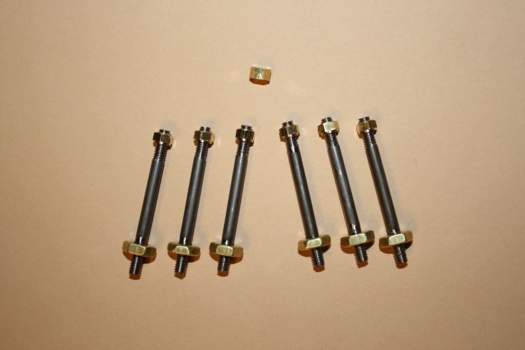
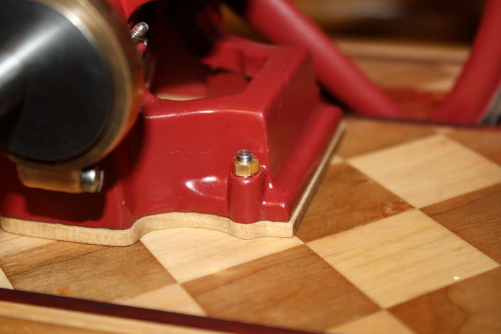
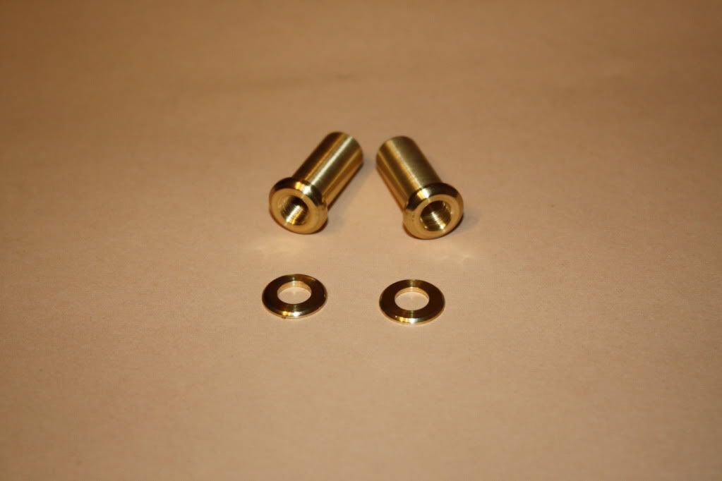
Well, this will be the last update for this build log. I made the nuts for the bearings caps today, and consider the engine "Built". I have a little touch up to do to the paint to fix some boo-boos that happened during the last assembly stages and a little cleaning to do. Once that is done I'll take some nice photos and a video and post them in the completed engines section.

This has been an amazing experience. Building the engine itself was fun, and logging my progress here has been more rewarding than I ever expected. If you have never done a build log, I highly recommend it. This log has taken more time than I expected, and it isn't nearly as complete in terms of documentation as I had hoped for. However, I'd do it again in a heartbeat.

A while back, I promised to share anything that I would do differently now that the engine is done. There are really only three major things I would change, and they relate to the order of operations on some of the castings.

First: I would make the first operation on the frame (after I had it mounted to the reference plate) to machine the main bearings. It would be much easier to locate all of the other components by indexing off a piece of 3/8" rod stuck through the bearings than it was to figure out how to locate the bearings after I had machined everything else. I suspect this is true for most engines of this configuration, but I had to learn that lesson somewhere...

Second: I would reference all of the steam chest operations from the center of the valve rod packing gland. It takes a pretty heavy cut to get the steam chest walls down to where the valve rod will enter near the center of the gland, and I missed by quite a bit.

Third: I would pay more attention to the length of the cylinder casting before taking the first cuts. I chucked the cylinder up in the lathe without measuring the length of the casting. Since the drawings call for a cleanup pass, that is all I did on the first end. However I really needed to take off more like 0.100". As a result, I could not machine enough off the outboard end to make the cylinder the correct length.

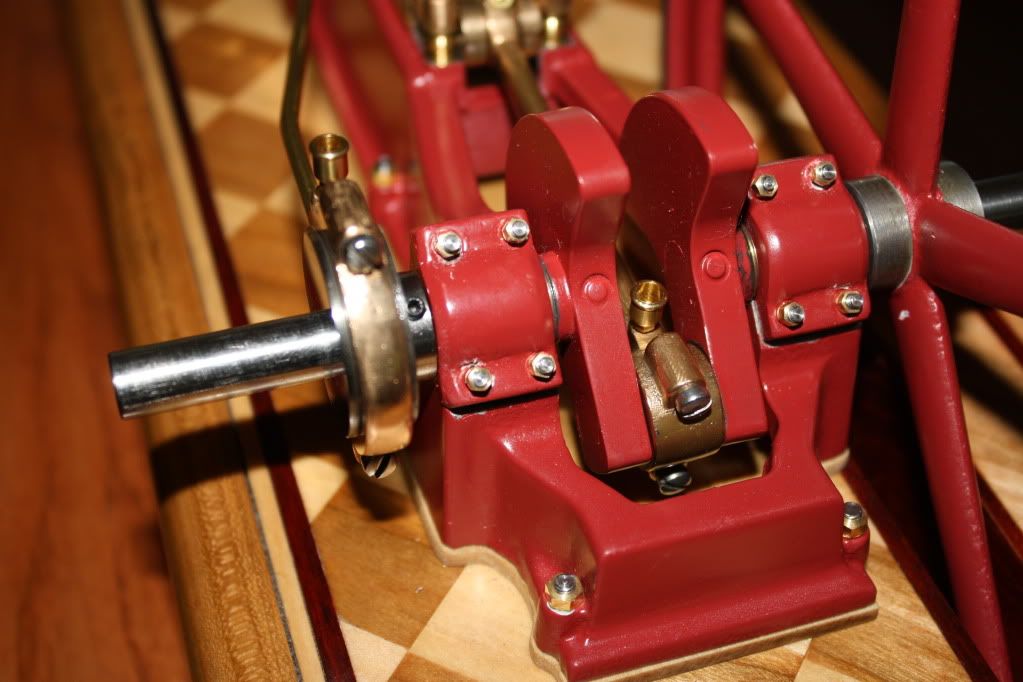
Some may question why I left the original kit cap-screws in place on the con-rod and the eccentric. I had intended to do the stud/nut thing there, but when I tried it I didn't like the look of the brass nut against the bronze. It looked OK against the cross head slides, but not with the rod. Maybe some day I'll make some steel bolts to put in those locations. Then again, maybe I won't :)

Thanks again to all of you who encouraged me along the way. It really does help a lot when people post little comments along the way. I am more than a little sad that so many of the folks who were following along decided to leave the forum over the last few weeks. It is selfish of me to want them to see this engine completed, but I do hope some of them are still watching in silence.

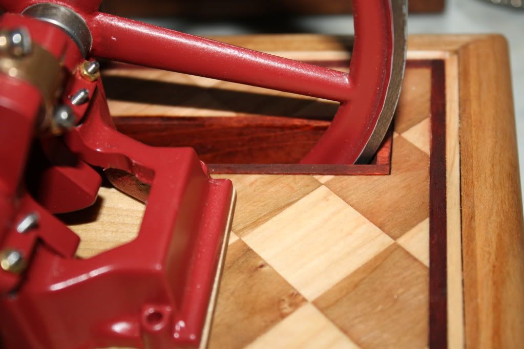
Here is a shot of the bearing caps with the new nuts. You can see several of the chips in the paint that I need to touch up:
IMG_1842.jpg


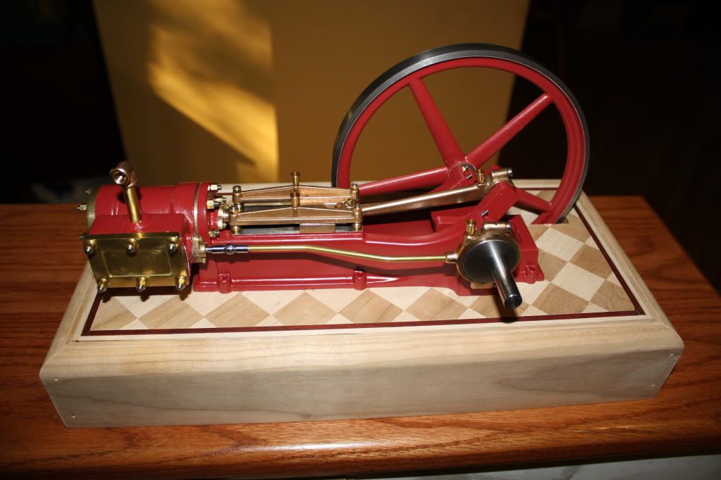
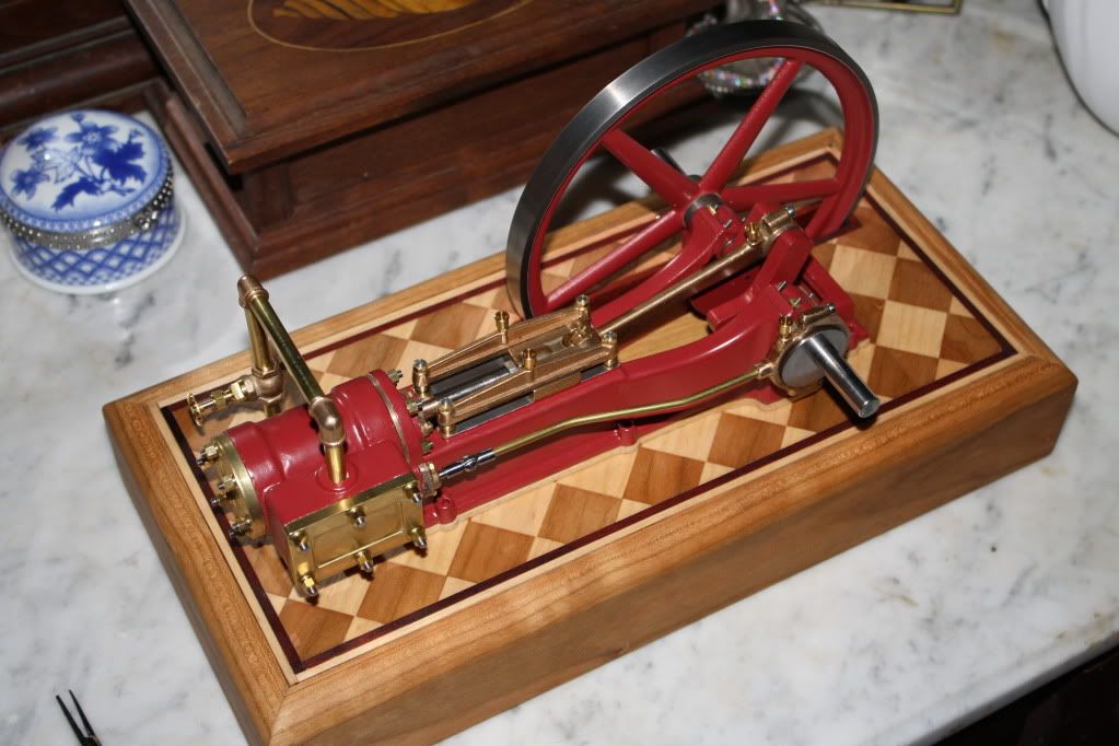
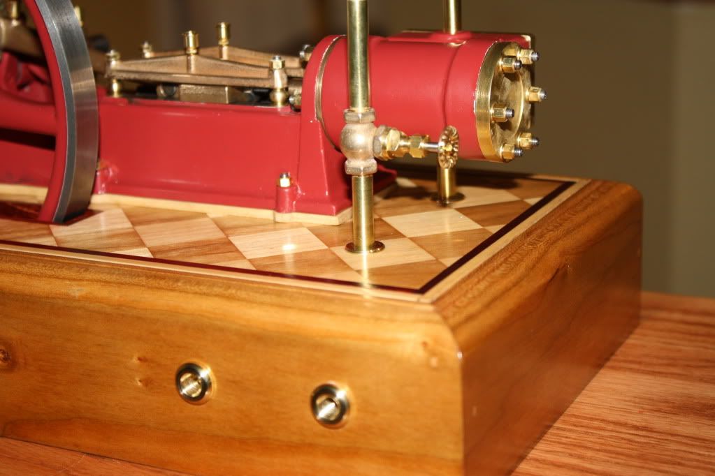
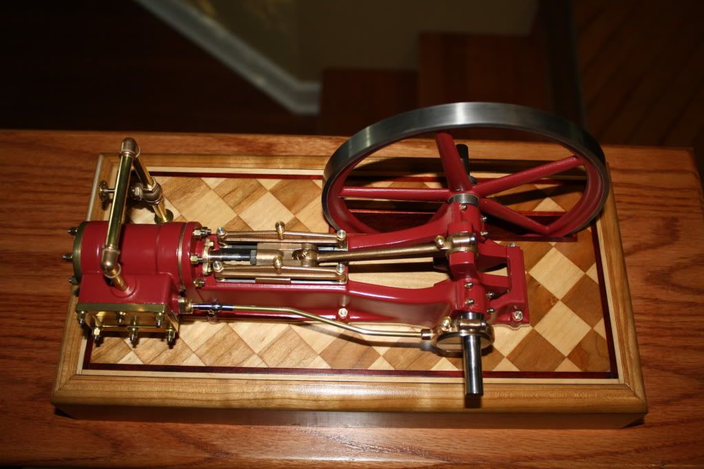
Here is a teaser shot of the whole engine:

IMG_1843.jpg
 
Last edited:
Well done Brian, if I can get mine to look anything like as good I will be happy:)
 
Thanks guys :)

Dave, I am going to start an Upshur farm engine next. It will be my first IC engine.
 
Back
Top